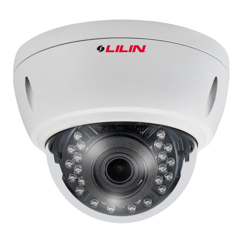
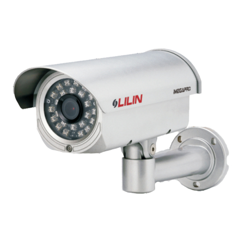
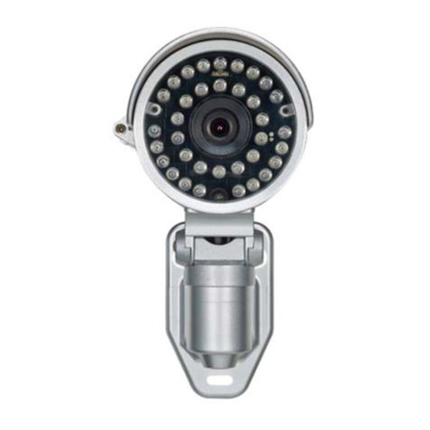
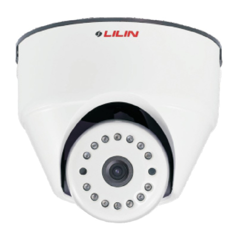
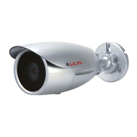
Lilin CMR70826 N/P User manual

MERIT LILIN ENT. CO., LTD
http://www.meritlilin.com
INSTRUCTION MANUAL
CMR7082/7084/7088 N/P 3.6/6
66-CMR708CSE
D/N ATR 700TVL IR CAMERA
CMR7082X3.6 N/P
D/N ATR 700TVL VARI-FOCAL IR CAMERA

IMPORTANT SAFEGUARDS
GRAPHIC SYMBOL EXPLANATION
The lightning flash with arrowhead symbol, within an equilateral
triangle, is intended to alert the user to the presence of
uninsulated "dangerous voltage" within the product's enclosure
that may be of sufficient magnitude to constitute a risk of electric
The exclamation point within an equilateral triangle is intended
to alert the user to the presence of important operating and
maintenance (servicing) instructions in the literature
shock to persons.
accompanying the unit.
CAUTION
RISK OF ELECTRIC SHOCK
DO NOT OPEN
CAUTION
TO REDUCE THE RISK OF ELECTRIC SHOCK,
DO NOT REMOVE COVER (OR BACK)
NO USER SERVICEABLE PARTS INSIDE.
REFER SERVICING TO QUALIFIED
SERVICE PERSONNEL.
CAUTION
RISK OF EXPLOSION IF BATTERY IS REPLACED
BYAN INCORRECT TYPE.
DISPOSE OF USED BATTERIES ACCORDING
TO THE INSTRUCTIONS

CAUTION
Do not drop or strike this equipment.
Do not install the equipment near any naked flames or heat
sources.
Do not expose this unit to rain or excessive moisture, avoid
smoke and dust.
Do not cover cloth or to install this unit in poorly ventilated
places.
Do not continue to operate if there appears to be fault.
Do not touch the power connection with wet hands.
Do not damage the power cord or leave it under pressure.
Sensitive electronics inside are vulnerable to excessive shock.
Excessive heat could damage this unit.
Please the camera in an environmental housing for protection.
If the camera gets wet, unplug it and have it checked by
qualified service personnel.
This may lead to overheating.
If the unit ceases to function, contact qualified service
personnel for help.
Risk of short circuit or electric shock.
Risk of fire or shock circuit.

CONGRATULATIONS
Thank you for purchasing this D/N ATR 700TVL (Vari-Focal)IR
Camera. You now own one of the many fine CCTV products we
manufactured. This product has been carefully inspected under
rigid quality control and should reach you in perfect condition.
With reasonable care, it will provide years of reliable performance.
We recommend that you read this installation and operation
manual thoroughly before installing and operation your new
system.
Here you will find all the information you need to set up and use
the system. If any questions are not answered in the manual,
please contact your dealer.
Before proceeding, please read and observe all instructions and
warnings contained in this manual. Retain this manual with the
original bill of sale for future reference and, if necessary, warranty
service.
When unpacking your new camera, check for missing or damaged
items. If any item is missing, or if damage is evident,
I . Contact your dealer for
assistance.
DO NOT
NSTALL OR OPERATE THIS PRODUCT

WARRANTY INFORMATION
Please complete the following product purchase information. The
factory will requests this information when contacted for technical
support, or warranty repair. It is also valuable in case of loss or
theft.
Purchase Date
Serial Number
Model Number

TABLE OF CONTENTS
PART DESCRIPTION & DIMENSION
INSTALLATION
CONFIGURATION OF THE MENU
SETTING MENU AND FUNCTION
To Open and Exit the Menu screen
LENS
SHUTTER/AGC
WHITE BAL (White Balance)
BACKLIGHT (Backlight Compensation)
PICTADJUST (Picture Adjust)
ATR (Adaptive Tone Reproduction)
PRIVACY
NR (Noise Reduction)
CAMERA ID
SYNC
LANGUAGE
CAMERA RESET
SPECIFICATIONS
1
2
7
9
9
9
10
12
14
15
16
16
17
18
19
19
19
20

1
TOP COVER
BOTTOM CHASSIS
BRACKET
PAN ADJUSTMENT SCREW
TILT ADJUSTMENT SCREW
WINDOW
VIDEO OUTPUT JACK (CMR7082)
DC POWER INPUT JACK (
)
DC12V 10%,
CMR7082
Unit: mm
154
101
72.5
67
82
PART DESCRIPTION & DIMENSION

2
DC power input
Video output
INSTALLATION
FIG. 1 FIG. 2
1. CMR7082
1-1. Take out the camera from the inner box first. Plug the video cable and
power cable to video output jack and DC power input jack of the camera
(FIG.1). Then fix bracket to the wall(FIG.2).
1-2. Loosen the screws of top cover with screw driver(FIG.3).
FIG. 3
2. CMR7084/8
2-1. Take out the camera from the inner box first. Loosen the pan adjustment
screw with hexagon screw driver. Then, separated the bracket from the
camera body(FIG.4). Put the power cable and video cable through the
bracket and then fix it to the wall(FIG.5&FIG.6).

3
FIG. 4
FIG. 6
FIG. 5
2-2. Open the top cover with screw driver(FIG.7).
FIG. 7
2-3. Next, Put the power cable and video cable through the bottom chassis and
rubble(FIG.8) and then fix the camera body on the bracket(FIG.9).

4
Video Output Video Cable
FIG. 9
FIG. 8
2-4. Plug and fix the power cable to the terminal and plug the video cable to
vidoe output of the camera(FIG.10). Also for the security, please use the
adhesive tape to wrap the connection of video cable(FIG.11).
FIG. 11
FIG. 10
Live
Earth
Neutral
NL
Note : When using two-cord
power cable, please
connect them to
"Live" and "Neutral".
3. Loosen the pan and tilt adjustment screw on the bracket to turn the camera body
to the desired angle and then tighten the screws(FIG.12).

4-1. USER OSD SETTING
Setting switches and Functions.
A. (UP)
B. (LEFT)
5
FIG. 12
4. First, adjust the lens on focus and zoom to form the optimal video image after
that tighten the screws(FIG.13). Then adjust the OSD menu to form the
optimal image. Please refer to page7~19.
: Press to move the cursor upwards or to select
items.
: Press to move the cursor to the left and to select
or adjust the parameters of the selected item.
The parameters changes each time this button is
pressed.
FIG. 13
F
TW
ZOOM
FOCUS
N
RIGHTLEFT
DOWN
UP
SET

6
FIG. 15
5. Replace the top cover and tighten the screws(FIG.14&FIG.15).
FIG. 14
C. (RIGHT)
D. (DOWN)
E. SET : Executes selections and displays a submenu for an
item with the mark.
: Press to move the cursor to the right and
select or adjust the parameters of the selected
item. The parameters changes each time this
button is pressed.
: Press to move the cursor downwards or to select
items.

CONFIGURATION OF THE MENU
SETUP
MENU
LENS
SHUTTER/
AGC
AUTO
AUTO
MANUAL
MANUAL
HIGH LUMINANCE
LOW LUMINANCE
MODE SHUT+AGC
SHUTTER 1/60(1/50) 1/100(1/120) 1/250~1/10000//
AGC 6.00 12.00 18.00 24.00 30.00 36.00 42.00 44.80///////
MODE
MODE AGC OFF
/
BRIGHTNESS(000~255)
BRIGHTNESS x0.25 x0.50 x0.75 x1.00
///
AUTO IRIS
SHUT+AUTO IRIS
MODE AUTO OPEN CLOSE//
SPEED(000~255)
TYPE DC
WHITE BAL
ATR
PICT ADJUST
BACKLIGHT BLC HLC OFF
//
ATW
OFF
MIRROR OFF/ ON
B-GAIN(000~255)
B-GAIN(000~255)
LUMINANCE LOW MID HIGH
//
SPEED(000~255)
PUSH
ON
BRIGHTNESS(000~255)
CONTRAST(000~255)
SHARPNESS(000~255)
HUE(000~255)
GAIN(000~255)
R-GAIN(000~255)
R-GAIN(000~255)
CONTRAST LOW MIDLOW MID MIDHIGH HIGH
/// /
DELAY CNT(000~255)
USER 1
USER 2
ANTI CR
MANUAL LEVEL(000~255)
PUSH LOCK
ATW FRAME x0.50 x1.00 x1.50 x2.00
///
ENVIRONMENT INDOOR OUTDOOR/
7

PRIVACY OFF
AREA SEL 1/8~8/8
ON
TOP [000~244(NTSC), 000~288(PAL)]
BOTTOM [000~244(NTSC), 000~288(PAL)]
LEFT [000~474(NTSC), 000~468(PAL)]
RIGHT [000~474(NTSC), 000~468(PAL)]
COLOR(1~8)
TRANSP 0.00 0.50 0.75 1.00
///
MOSAIC OFF ON/
NR NR MODE Y/C OFF/ Y/ C
/
Y LEVEL(000~015)
C LEVEL(000~015)
CAMERA ID
SYNC INT
LANGUAGE ENGLISH// / / / /
/
DEUTSCH FRANCAIS PYCCK PORTUGUES
ESPANOL
OFF
ON
NN
^
^
CAMERA RESET
8

9
SETTING MENU AND FUNCTION
TO Open and Exit the Menu screen
1. Press "SET" button.
The Menu screen appears on the monitor. Check the current settings on
the menu.
2. Push or button to select the options then use or button to select a
mode.
NEXT: To the next setup menu.
BACK: Return to the previous.
RETURN: Return to the previous.
SAVE ALL: Used to save the various setting of the internal OSD menu
in the EEPROM together.
EXIT: Exit the setup menu.
SETUP MENU
AUTO
AUTO
ATW
BLC
OFF
OFF
LENS
SHUTTER/AGC
WHITE BAL
BACKLIGHT
PICTADJUST
ATR
PRIVACY
NEXT
EXIT SAVE ALL
SETUP MENU
OFF
INT
ENGLISH
NR
CAMERA ID
SYNC
LANGUAGE
CAMERA RESET
BACK
EXIT SAVE ALL
LENS
This function is used to set the mechanical iris of the lens.
1. Select [LENS] option.
2. Push or button to select a mode.
LENS mode changes as follows:
AUTO: Select the auto iris lens.
MANUAL: Select the manual iris lens.
3. Select an AUTO then press "SET" button.
The AUTO IRIS menu appears.
AUTO MANUAL
AUTO IRIS
DC
AUTO
080
TYPE
MODE
SPEED
RETURN

10
AUTO (AUTO IRIS)
FUNCTION OPTION DESCRIPTION
TYPE
SPEED
MODE
DC
000~255
AUTO
OPEN
CLOSE
Sets the type of mechanical iris.
DC: Direct drive signal.
Sets the convergence speed of the
mechanical iris.
Sets the type of control to be exercised over
the mechanical iris.
AUTO: The mechanical iris is controlled
automatically.
OPEN: The mechanical iris is fixed to open.
CLOSE: The mechanical iris is fixed to close.
1. Without LENS option in the CMR7082/7084/7088N/P .
2. Only DC mode on the TYPE option. Because a DC auto iris lens is used with the
CMR7082X3.6N/P.
NOTES
SHUTTER/AGC
This function is used to set AE(Auto Exposure) or ME(Manual Exposure).
1. Select [SHUTTER/AGC] option.
2. Push or button to select an AUTO or
MANUAL then press "SET" button. The
AUTO SETUP or MANUAL SETUP menu
appears.
SHUTTER/AGC mode changes as follows:
AUTO: Select the AE control.
MANUAL: Select the ME control.
AUTO MANUAL
AUTO SETUP
SHUT+AUTO IRIS
024
AGC
x0.50
HIGH LUMINANCE
BRIGHTNESS
LOW LUMINANCE
MODE
BRIGHTNESS
RETURN
MODE

11
AUTO (AE)
FUNCTION OPTION DESCRIPTION
HIGH
LUMINANCE
AUTO IRIS
SHUT+AUTO IRIS
Specifies AE control on the medium
and high brightness side.
AUTO IRIS: Fixed electronic shutter.
[1/60sec.(NTSC), 1/50sec.(PAL)]
SHUT+AUTO IRIS: Auto electronic
shutter.
[1/60sec.(1/50sec.)~1/100,000sec.]
MODE
000~255 Specifies the medium and high
brightness side reference.
BRIGHTNESS
LOW
LUMINANCE
AGC
OFF
Specifies AE control on the low
brightness side.
AGC: AGC ON
OFF: AGC OFF
MODE
x0.25
x0.50
x0.75
x1.00
Specifies the low brightness side
reference.
BRIGHTNESS
MANUAL (ME)
FUNCTION OPTION DESCRIPTION
MODE SHUT+AGC "SHUT+AGC" is the only option available
for the ME operation mode. There are no
other options.
MANUAL SETUP
SHUT+AGC
1/60
6.00
MODE
SHUTTER
AGC
RETURN

12
AGC
SHUTTER
6.00
12.00
18.00
24.00
30.00
36.00
42.00
44.80
1/60(NTSC), 1/50(PAL)
1/100(NTSC), 1/120(PAL)
1/250
1/500
1/1000
1/2000
1/4000
1/10000
Sets the AGC value(dB) for ME.
Sets the ME shutter speed(in fractions
of a second).
Please select AUTO mode on the SHUTTER/AGC option. If you select MANUAL
mode, the over exposure may occur.
NOTE
WHITE BAL (WHITE BALANCE)
This function is used to set the white balance operation mode.
1. Select [WHITE BAL] option.
2. Push or button to select a mode.
WHITE BAL mode changes as follows:
ATW PUSH USER1 USER2
PUSH LOCK MANUAL ANTI CR
ATW
239
016
x1.00
INDOOR
SPEED
DELAY CNT
ATW FRAME
ENVIROMENT
RETURN
ATW (Auto Tracking White balance)
This function automatically tracks the changes in the color
temperature, and adjusts the white balance.
The color temperatures ranging from 1800K to 10500K.

13
FUNCTION OPTION DESCRIPTION
SPEED
DELAY CNT
ATW FRAME
ENVIROMENT
000~255
000~255
x0.50
x1.00
x1.50
x2.00
INDOOR
OUTDOOR
Adjusts the pull-in speed of ATW.
Sets the time-based hysteresis of ATW.
Sets the pull-in frame magnification.
Sets the pull-in frame(indoor/outdoor) of ATW.
INDOOR: Select the indoor pull-in frame.
OUTDOOR: Select the outdoor pull-in frame.
PUSH (Full pull-in)
This function adjusts the white balance regardless of the subject
conditions.
USER2 WB
045
026
B-GAIN
R-GAIN
RETURN
USER1 WB
029
034
B-GAIN
R-GAIN
RETURN
USER1
The gain values for the outdoor fixed mode are used as the adjustment
items of USER1 on the internal OSD menu.
USER2
The gain values for the fluorescent light fixed mode are used as the
adjustment items of USER2 on the internal OSD menu.
FUNCTION OPTION DESCRIPTION
B-GAIN
R-GAIN
000~255
000~255
Used for the B gain operation in the WB fixed
gain mode.
Used for the R gain operation in the WB fixed
gain mode.

14
ANTI CR (Color Rolling suppression)
This function minimizes the color changes(color rolling) over long
periods caused by very small differences between the flicker frequency
of non-inverter fluorescent lights and the drive frequency of the image
sensor devices.
MANUAL (Manual WB)
The B and R gain values for manual WB are set on this screen.
MANUAL WB
058
LEVEL
RETURN
FUNCTION OPTION DESCRIPTION
LEVEL 000~255 Sets the B and R gain values for manual WB.
By incrementing or decrementing the B gain
value, the R gain value is also adjusted in
tandem.
PUSH LOCK (Hold)
The WB gain level established when operation has transferred to the
PUSH LOCK mode is held.
1. Push or button to select [PUSH LOCK] Mode then press "SET"
button.
BACKLIGHT (BACKLIGHT Compensation)
This function is used to set the backlight compensation operation.
1. Select [BACKLIGHT] option.
Table of contents
Other Lilin Security Camera manuals

Lilin
Lilin PIH 7000IP User manual

Lilin
Lilin iMEGAPRO IPD2220-IVS User manual

Lilin
Lilin ZHR8182 User manual

Lilin
Lilin iMegapro IPR7722ESX User manual

Lilin
Lilin CMR6082X User manual

Lilin
Lilin CMD2422S User manual

Lilin
Lilin IPG1052ES User manual

Lilin
Lilin PSR5024EX20 User manual

Lilin
Lilin iMEGAPRO IPR2522ES User manual

Lilin
Lilin PIH-7635DH Series User manual

Lilin
Lilin IPS 8264 User manual

Lilin
Lilin ZMR7442X-P User manual

Lilin
Lilin MR6322 User manual

Lilin
Lilin PIH - 7625 User manual
Lilin
Lilin IPD552EX4.2 N User manual

Lilin
Lilin CMD2182 User manual

Lilin
Lilin ATR 700TVL User manual
Lilin
Lilin iMEGAPRO IPR7922E User manual

Lilin
Lilin SP2034 Series User manual

Lilin
Lilin Ultra Series User manual