Lilin 7000MPG4OOE User manual

Network Dome Camera
User’s Manual
Version:1.0
Date:09/01/06

Content
1. Introduction................................................................................................................................................................................3
1.1. What is Network Dome Camera?.......................................................................................................................................3
1.2. Advantage Features ...........................................................................................................................................................4
2. Physical Connections ................................................................................................................................................................5
2.1. Structural Element..............................................................................................................................................................5
2.2. Connection Jack and Cable Requirement..........................................................................................................................6
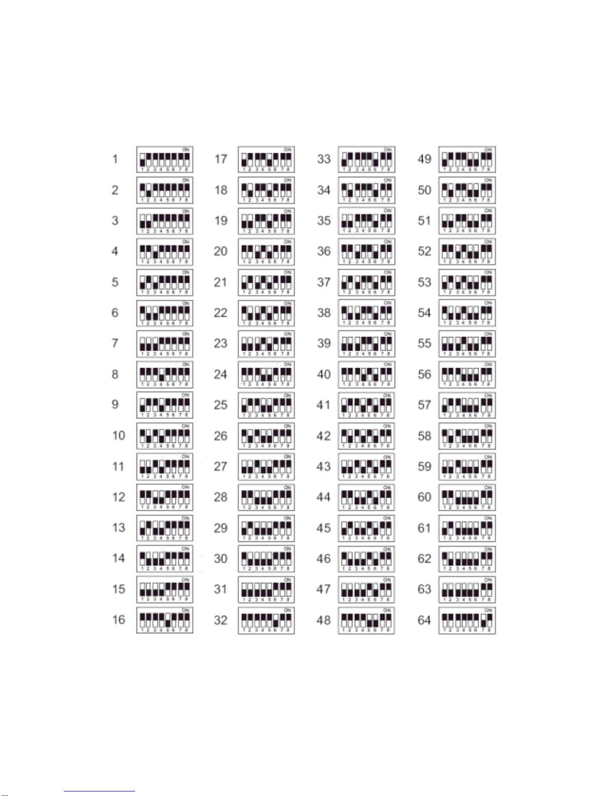
2.3. DIP Switch Setting..............................................................................................................................................................8
2.4. NDC ID Address Setting Refer Chart .................................................................................................................................9
3. Installation ...............................................................................................................................................................................10
3.1. Installation Preview ..........................................................................................................................................................10
3.2. Hardware Installation........................................................................................................................................................11
– Indoor Installation Structural Drawing...............................................................................................................................11
– Outdoor Installation Structural Drawing (Pendant Mounting)............................................................................................12
– Embedded Mounting (False Ceiling) ................................................................................................................................13
– Attached Mounting (Fixed Ceiling) ...................................................................................................................................16
– Pendant Mounting (External Housing)..............................................................................................................................18
3.3. Software Installation .........................................................................................................................................................23
3.4. Network Configuration......................................................................................................................................................24
– Preparation before IP Assignment....................................................................................................................................24
– Using IP Installer ..............................................................................................................................................................24
4. Usage of Web-based User Interface .......................................................................................................................................27
4.1. Browse Live Video............................................................................................................................................................27
– Menu Language Selection................................................................................................................................................27
– Video Channel Selection ..................................................................................................................................................28
– Pan / Tilt / Zoom Control...................................................................................................................................................28
– Digital Zoom Selection .....................................................................................................................................................29
– On/Off the Audio, and Rotate the Video ...........................................................................................................................29
4.2. Recording the Video and Audio........................................................................................................................................30
4.3. Video Conference.............................................................................................................................................................31
– Control the Video in Location Window..............................................................................................................................31
– Setting for Video Record ..................................................................................................................................................32
– Select the Remote Device................................................................................................................................................32
– Manually Set Up Additional Camera.................................................................................................................................33
5. Configuration of Web-Based User Interface ............................................................................................................................34
5.1. Configuration Preview ......................................................................................................................................................34
5.2. Configuration of A/V Setting .............................................................................................................................................35
– Basic A/V Settings............................................................................................................................................................35
– Advanced A/V Settings.....................................................................................................................................................36
1

– Image Adjustment.............................................................................................................................................................37
5.3. Setting External Sources..................................................................................................................................................38
5.4. PTZ Settings ....................................................................................................................................................................38
– Setting the ID for Network Dome Camera........................................................................................................................39
– Operating the Dome Camera ...........................................................................................................................................40
– Preset Point Setting..........................................................................................................................................................41
– Setting Day / Night Mode (available for 25X NDC)...........................................................................................................42
– Setting the Lens Speed for Zoom Control (available for 25X NDC)..................................................................................43
– Setting More Functions for NDC (available for 25X NDC)................................................................................................43
5.5. On Screen Display ...........................................................................................................................................................44
5.6. Configuration of Network Setting......................................................................................................................................45
– General Settings ..............................................................................................................................................................45
– Dynamic DNS Settings.....................................................................................................................................................46
5.7. Configuration of System ...................................................................................................................................................48
– System Information ..........................................................................................................................................................48
– Time Configuration ...........................................................................................................................................................48
– User Settings....................................................................................................................................................................49
6. Advanced Settings for 25X Network Dome Camera................................................................................................................51
6.1. Call Out the OSD Setup Menu .........................................................................................................................................51
6.2. Special Functions .............................................................................................................................................................51
6.3. Camera Settings ..............................................................................................................................................................53
6.4. Lens Control.....................................................................................................................................................................65
7. Surveillance System Configuration..........................................................................................................................................67
7.1. NDC and Keyboard ..........................................................................................................................................................67
7.2. Initial Power Up Inspection...............................................................................................................................................69
7.3. Operating NDC with Keyboard .........................................................................................................................................69
8. Specifications ..........................................................................................................................................................................78
Appendix A Upgrading the Software...........................................................................................................................................83
Appendix B Upgrade Custom Web Pages .................................................................................................................................86
Appendix C Emergency Factory Default ....................................................................................................................................88
Appendix D Quick Reference Table............................................................................................................................................89
Appendix E Trouble Shooting.....................................................................................................................................................90
Appendix F Installation Kit..........................................................................................................................................................91
2

1. Introduction
1.1. What is Network Dome Camera?
The Network Dome Camera (“NDC” here and after) is an Internet-based digital Network Speed Dome Camera, it built
in Pan/Tilt/Zoom and CCD module to distribute the compressed live video into Intranet/Internet through Ethernet
connection.
NDC can be moved (Pan/Tilt/Zoom) the view point to get the best monitoring angle easily via standard browser such
as ExplorerTM or NetscapeTM.
NDC is self-contained Web Server. Users could access the Network Dome Camera just like browsing website over
Internet using standard browser such as ExplorerTM or NetscapeTM , and do all the management, configuration, and
monitoring easily.
NDC contains an MPEG-4 image compression chipset capable of delivering streaming, constant or variable bit rate
MPEG-4 video over the network in real-time.
3

1.2. Advantage Features
There are two types of the Network Dome Camera – 22X NDC and 25X NDC. The specifications and functions will be
different between these two types.
Auto Focus Lens
Build-in 22X optical zoom lens with focal length 3.9 ~ 85.4 mm (22X NDC)♦
♦
♦
♦
♦
♦
♦
Build-in 25X optical zoom lens with focal length 3.8 ~ 95.0 mm (25X NDC)
Digital Zoom
Automatic / Manual Iris Control
360ocontinuous rotation
Up to 128 programmable preset positions
Preset positions auto scanning
High speed rotation and tilt, speed range varies from 0.18°/sec ~ 360°/sec
180° Horizontal Instant Flip
6 alarm inputs, 1 alarm output can be set as NO (normally open) or NC (normally close) for each NDC
Two types of alarm response mode: Lock Mode, Release Mode
Build in 1/4” CCD high resolution DSP color camera:
Color / Mono switch (IR Cut Filter) (25X NDC)
480 TV Lines (Color); 520 TV Lines (Mono)
0.1Lux (Color); 0.01Lux (Mono)
White Balance Control (Auto White Balance and Manual White Balance (Indoor/Outdoor))
Back Light Compensation (ON/OFF)
Auto Gain Control (ON/OFF)
On-Screen Setup Menu (25X NDC)
Dynamic Privacy Zone (25X NDC)
RS-485 control interface
Up to 64 NDC configuration
Compatible with PC control (protocol required)
12V DC voltage input (power supply options: AC 90~260V or AC 24V)
Flexible Mounting:
Indoor-embedded and attached types
Outdoor-with weather resistant housing
4

2. Physical Connections
2.1. Structural Element
1. Dome Cover 6. Video In /Out Jack
2. Camera Case 7. Power In Jack
3. Decoration Ring 8. Ethernet Port
4. RS-485 In/Out Jack Ethernet/Power/Status/Network LED
5. Alarm In/Out Jack 9. Camera Base
5

2.2. Connection Jack and Cable Requirement
Power In Jack
DC12V Input Voltage, Power Consumption 1.2Adc, Center Pin 2.0mm
Require Cable: 18 AWG x 2C
Video Out BNC Jack
Video Signal Output CVBS 1.0Vpp 75∩BNC
Recommend Data Cable:5C2V
Alarm In/Out Jack
Each NDC contains 6 alarm inputs and 1 alarm output
Alarm Input Voltage 5.6V max, Output 0.5A 120Vac/ 1A 24Vdc
Recommend Data Cable: UL 26 AWG 80 C 300V UL 24 AWG 80 C 300V
6

RS-485 In/ Out Jack
RS-485 Input (TXDI+, TXDI-) to receiver signal from keyboard, matrix, DVR or multiplexer through twisted
pair cable.
RS-485 Output (TXDO+, TXDO-) sending out signal to next NDC through twisted pair cable.
Recommend Data Cable: 2547 VW-ISC UL 24 AWG x 2C
Transmission Distance: Max. 1 Kilometer
* When 24VAC PSU is used, the recommend cables are:
UL SPT-1 VW-1 18AWG x 2C
UL SPT-2 VW-1 18AWG x 2C
UL SUT 105C VW-1 18AWG x 3C
The distance between 24Vac PSU and fast dome cannot exceed 200 meters.
Ethernet
Standard IEEE 802.3 10 /100 Base-T port
Power/Status LED
Power On: constant red.
Emergency factory default (appendix C): Blinking orange (i.e. red mix with green).
Network LED
Network Link (connected): Constant red.
Networks have activities: Blink red.
Data sent out from server: Blink green.
Network disconnected: Constant slow blinking green.
Upgrading software (appendix A): Constant slow to fast blinking of orange.
7

2.3. DIP Switch Setting
Fan Power Switch
Turn the number 2 switch to ON position to activate the internal fan. This will maintain the temperature inside and
make electric parts life.
Alarm Mode Switch
Alarm Mode can be set as Lock or Release mode. Turn number 1 switch to ON position to choose Release mode.
Turn number 1 switch to OFF position to choose Lock mode. The NDC has 6 alarm inputs and 1 output, which
can be set either NC (normally close) or NO (normally open) mode. Turn number 2 switch to NO position to
choose NC mode. Turn number 2 switch to OFF position to choose NO mode.
Camera Function Switch
Turn number 1 switch to ON position for AGC function
Turn number 1 switch to ON position for BLC function
Turn number 1 switch to ON position for AWB function
Turn number 1 switch to OFF position for Manual White Balance (MWB)
When the NDC is set to MWB, turn number 4 switch to ON for Outdoor (color temp. 3200K) or to OFF for
Indoor (color temp. 6300K)
8

2.4. NDC ID Address Setting Refer Chart
Up to 64 NDC can be serial linking in one system. Therefore each dome is addressing by ID switch located at the base
of the NDC. Below is the address setting for camera 1~64:
9

3. Installation
3.1. Installation Preview
There are 3 mains steps required to perform a successful installation:
Hardware installation
Software installation
Network configuration
Hardware installation consists of connecting cables to the NDC including network, video, and power cables.
Software installation consists of the installation of software that is necessary to properly view the video from the NDC
or to configure the NDC itself. The software includes:
IP Installer -- a utility for locating devices and configuring network settings on a LAN.
Component Installer -- installs all ActiveX components used by the device for things such as video display and
configuration.
Macromedia Flash Player -- necessary for displaying some components of the Web UI.
The following are not necessary, but may be used for added convenience:
6016 Recording Software -- displaying and recording up to 16 channels simultaneously. Both the MPEG-4 and
MJPEG devices are supported.
Xvid -- a MPEG-4 codec. If no other MPEG-4 codecs (ie. DivX, 3ivX, ffdshow, etc.) are installed on your computer,
the Component installer will install this for you.
QuickTime or VLC -- though not necessary, this can be used for viewing the MPEG-4 stream without a Web
browser.
Network configuration consists of modifying the network settings for the NDC in order to successfully connect to the
device.
10

3.2. Hardware Installation
– Indoor Installation Structural Drawing
11

– Outdoor Installation Structural Drawing (Pendant Mounting)
12

– Embedded Mounting (False Ceiling)
13

14

Note: After dome cover is attached, use glass-cleaning cloth to clean dome cover. Unclean dome cover may
affect camera performance.
15

– Attached Mounting (Fixed Ceiling)
16

Note: After dome cover is attached, use glass-cleaning cloth to clean dome cover. Unclean dome cover may
affect camera performance.
17

– Pendant Mounting (External Housing)
O
Put the PSU into the
box
O
Tighten 2 screws to
fix the PSU
O
Put PSU into the box
O
Put the clamp on PSU
O
Tighten 2 screws to
fix the PSU
Step 1
Separate PSU and Bracket
Step 2
Install Power Supply Unit
1.1 When use 24Vacpower source:
1.2 When use 90 ~ 260Vac power source:
Step 3
Install the Power Box
Untighten the screws
from PSU box Untighten and pull out
the bolt from the hinge Separatethehousing
and PSUbox
Untightenthescrews
fromPSUboxand
openit.(SwanNeck)
144mm
244mm
Drill 4 holes on
desired locations Tighten4 screws to fix thepower box
(These four screws are not supplied.
User must prepare their own screws.)
Drill holes on the
intended positions of
of the wall. (Goose Neck)
70
70 50.8
50.8
45
。
ψ
10
ψ
8
18

E
N
L
E
N
L
L
N
E
RS-485 Alarm In Alarm Output
AC InputAC OutputFast Dome
Wiring
Fan &Heater
Wiring
DC12V Input
V
ideo Out
p
ut
O
Untighten the left
knob, put theAC
power cable through
the hole and tighten
the knob
O
Connect theAC
power cable toAC
Input jack
O
Connect theAC
power cable(below)
toAC Output jack
O
ConnecttheDC
powercable(above)
toDCInputjack
Step
4
Connection
4.1 ConnectAC / DC cables:
4.2 ConnectVideo cable:
Connect the video
cable to output jack
Untighten the middle
knob, put the video
cable through the hole
and tighten the knob
4.3 ConnectAlarm and telemetrycontrol (RS-485) cables:
GND
A
LARM 1
TXDI+
TXDI-
Untighten the right knob,
put the Alarmand RS-485
cables through the hole
and tighten the knob
Connect the
telemetry control
(RS-485) to RS-485
Input (TXDI+,TXDI-)
Connect theAlarm
input cable toAlarm
Input
(Alarm 1 & GND)
19
Table of contents
Other Lilin Security Camera manuals

Lilin
Lilin ImegaPro IPS6224M User manual

Lilin
Lilin AHD705A3.6 User manual

Lilin
Lilin PSD4624EX20 User manual

Lilin
Lilin SP9364 User manual

Lilin
Lilin PSR5024EX20 User manual

Lilin
Lilin IPC0122WP3 User manual

Lilin
Lilin 66-8322CSB-1B User manual

Lilin
Lilin IPR722-IVS User manual

Lilin
Lilin iMEGAPRO IPD2220ES User manual

Lilin
Lilin PIH-2522 User manual

Lilin
Lilin PIH-7635DH Series User manual

Lilin
Lilin PIH - 7000 User manual

Lilin
Lilin CMD072 series User manual

Lilin
Lilin iMegapro IPR7722ESX User manual

Lilin
Lilin CMD6182X User manual

Lilin
Lilin PIH - 7000 User manual

Lilin
Lilin MR8322 User manual

Lilin
Lilin ZR8022EX10 User manual

Lilin
Lilin ZHR8182 User manual

Lilin
Lilin iMEGAPRO IPG1022ES User manual