Lincoln Electric Torchmate 5100 Series Operating instructions

April 8, 2019
Copyright 2019
Lincoln Electric®Cutting Systems
SITE PREPARATION
GUIDE

Torchmate 5100 ii
Table of contents
Page: Contents
i Title Page
ii Table of Contents
1 Site Preparation, Machine and Plasma
2 Site Preparation, HD Spirit®II systems
3 Site Preparation, FlexCut®systems
4 5100 Connections, Air & Power
5 Machine Grounding
6 Site Preparation Sign-O Sheet
7 Table Specications
8 Customer Assistance Policy

1Site Preparation Guide
Site Preparation
• Physical space around the Torchmate 5100
When preparing to install the Lincoln Electric CNC Cutting System, provide sucient space to access the material
bed and connections around the entire machine. It is recommended that three feet of work space should be
maintained between the 5100 to any other objects.
When installing a Torchmate 5100 in your shop, there are many factors that will inuence the potential productivity,
ease of use of the machine and the safety of the operator. The main factors to prepare for include the physical layout
and placement of the machine in the shop, the availability of power, an EMI ground, compressed air and other gases,
and ventilation.
• Water Table vs. Downdraft
The Torchmate 5100 is oered in two congurations for fume control, a water table and a downdraft table. Each
has certain considerations to be taken when preparing to install and operate the 5100 machine. The water table
must have the ability to be lled with tap water frequently, especially in hot arid climates. A downdraft table must
have clearance at the back of the machine to run 14” ducting to the fume extraction source. This ducting may cross
a walkway or other cabling or hoses associated with the machine.
• Plasma Cutter Options
The Torchmate 5100 machine is oered with several plasma cutting power supplies. Each have dierent input
power requirements, gas type/volume requirements, etc. The site preparation guide generalizes this into two
categories, an Air Plasma site preparation for either the FlexCut 125 or FlexCut 200 plasma cutters. The HD guide
explains the requirements for the Spirit II model 275 and 400 plasma cutters.
• Dedicated Earth Ground
A dedicated earth ground must be provided and installed for the Torchmate 5100 machine. It should be installed
in a manner to reduce trip hazard, preferably nearest to the Star Ground located on the machine. This increases
the eectiveness of the ground, and reduces clutter with running long cables between the machine and a separate
ground.

Torchmate 5100 2
Locate power supply
within 6’ of table cable
chain. Automatic Gas
Console should be kept
within 2’ of power supply,
or installed on top of
power supply.
Lincoln Electric Kaliburn®Spirit II power supplies have a larger power box and a Automatic Gas Control box to mix
several dierent types of gases utilized in HD plasma cutting. The placement of these products in relationship to the
5100 must be within 6’ of the end of the cable chain. This also determines the location of incoming power to the Spirit
II plasma cutter, as well as the termination of gas leads to the Spirit II plasma cutters.
Site Preparation, Equipment Layout (HD)
113.25”
167”
Load From
This Side
Operator
Console
15’ Power Cord, Nema 5-15P
Shop Air Supply
Earth Ground (provided by customer)
MAINTAIN WORK AREA
5100 HD
Gases (provided by customer)
Placed within 15’ of Spirit II
Incoming AC power for
Plasma Cutter, Shop air
supply, and Termination of
gas hoses from Supply
43.0
30.0
Kaliburn
Spirit II
Power
Supply
The hose length from the Automatic Gas Control box to the source gas is provided at 25’. For steel and aluminum cut-
ting the Spirit II plasma cutter requires at minimum a 100% oxygen source, 100% nitrogen source, and Shop air. Consult
the Spirit II users manual for gas pressure and volume requirements.
14” Duct, Downdraft
Models Only

3Site Preparation Guide
Site Preparation, Equipment Layout (FlexCut)
113.25”
167”
Load From
This Side
Operator
Console
MAINTAIN WORK AREA
When installing a Torchmate 5100 in your shop paired with a FlexCut 125 or FlexCut 200 plasma cutter, consult the lay-
out below.
5100
FlexCut Plasma
(within 10’ of cable
carrier)
15’ Power Cord, NEMA 5-15P
Shop Air Supply
Earth Ground (provided by customer)
Incoming AC power for
Plasma Cutter
Shop air supply
14” Duct, Downdraft
Models Only

Torchmate 5100 4
Torchmate 5100 Connections
Internally the 5100 comes pre-wired and ready to run. All systems are test red and disconnected at the facility before
packaging and shipping. For shipping purposes, the plasma power supply is disconnected from the system and will
require a connection to the machine. The table has a single input power cord with a 120v NEMA 5-15P plug that powers
the table and computer/monitor. The plasma power supply chosen requires 3-phase electrical connections along with
numerous other connections that are required by your specic power supply to interface with the machine, consult the
specic plasma cutter manual for more details. Depending on the specic model plasma cutter, a power cord may not
be included.
All electrical, air, and interface connections
to the machine will be o of the BULKHEAD
5100 - Table Power and Air connections:
5100 - Pneumatic Connection:
Electrical Bulkhead
Attach the supplied 120v NEMA 5-15P plug into a wall outlet. This will power the electronics and table functions.
This should be a 120vAC @ 15amp circuit.
The 1/4” Industrial Quick Disconnect input on the bulkhead will distribute the air to the plasma power supply along
with table operations. Any accessories or collision sensors will also be provided shop air by tapping into the two
provided output 1/4” Tubing Push-Connects.
120v Power Cord
15’, NEMA 5-15P

5Site Preparation Guide
DETAIL A
GROUND ROD
STAR GROUND
A
Grounding Your Machine
Use 6 AWG Stranded Wire to connect the Star Ground on the table to the customer supplied dedicated earth ground.
For proper operation of your CNC cutting tables you are required to run a 6 AWG cable from the “star” ground to a
dedicated earth ground rod
Ground rod installations are covered by NEC Section 250.
Proper grounding must be provided to ensure personnel safety and to suppress high frequency noise. The foundation of
good grounding is an eective earth ground rod. A star ground point connects to the rod with a short, heavy conductor.
A simple copper clad steel rod can be driven into the ground to create a Grounding Rod. A ground rod must be installed.
Consult with a qualied electrical technician to verify your system grounding.
The FlexCut plasma unit is shipped with a factory
ground attached to the star ground. In addition, a
work ground is attached to the star ground to connect
to your material to be cut. If the work piece is painted
or dirty it may be necessary to expose the bare metal
to make a good electrical connection.
Place the plasma unit on the appropriate location.
Re-install the power lead and the table ground into
the plasma power supply.
Earth Ground Rod is not included with machine

Torchmate 5100 6
Site Preparation Sign-o Sheet
In order to maximize the amount of time the operators will receive during machine training, Lincoln Electric requires a
signed o completion sheet by the customer prior to scheduling an on-site machine commissioning or training. Please
Torchmate 5100 Customer Sign-Os:
• Machine is installed and fully leveled in the length and width
• 120vAC 15A circuit is installed and active
• Plasma Cutter AC circuit is installed and active
• Shop air is plumbed to the 5100 air manifold, and active
• Ground Rod is installed, and connected to the 5100
• Gas Supplies and Regulators are installed (HD Only)
• 426 gallons of tap water is available to ll water table (water table only)
• Fume Control system is plumbed to the machine and active (downdraft only)
Company/Site Name:
Responsible Installer:
Date:
Complete
• Plasma Cutter Torch and Coolant connections are connected
• Oxy Fuel Accessory Connected to Oxygen/Preheat gas (if applicable)

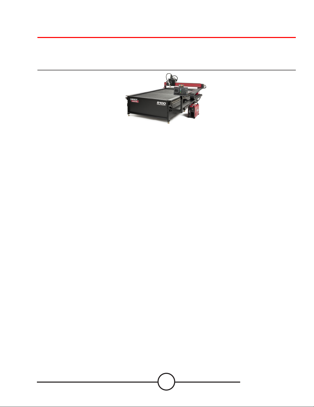
7Site Preparation Guide
Input Power
• 120V / 1Ph / 15A / 60Hz (table and computer)
• 380-600V / 3Ph / 50-60Hz (Plasma Power Supply specic)
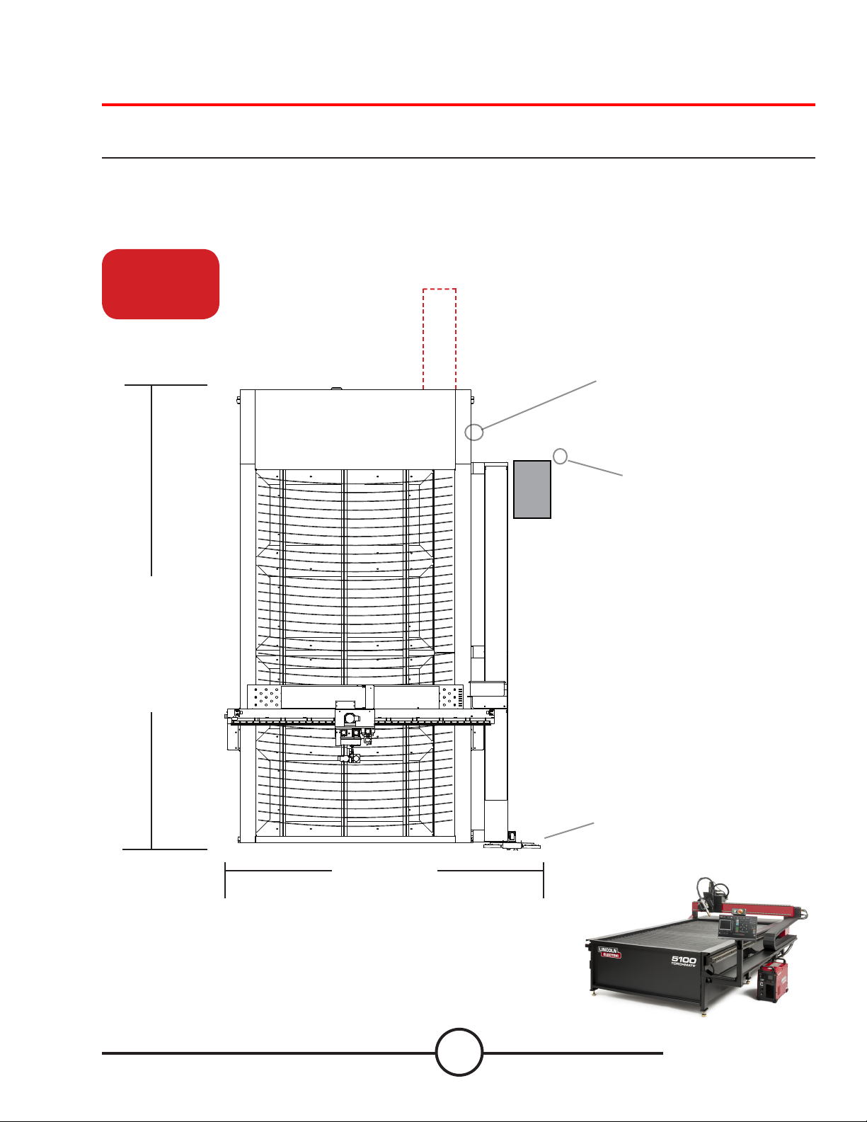
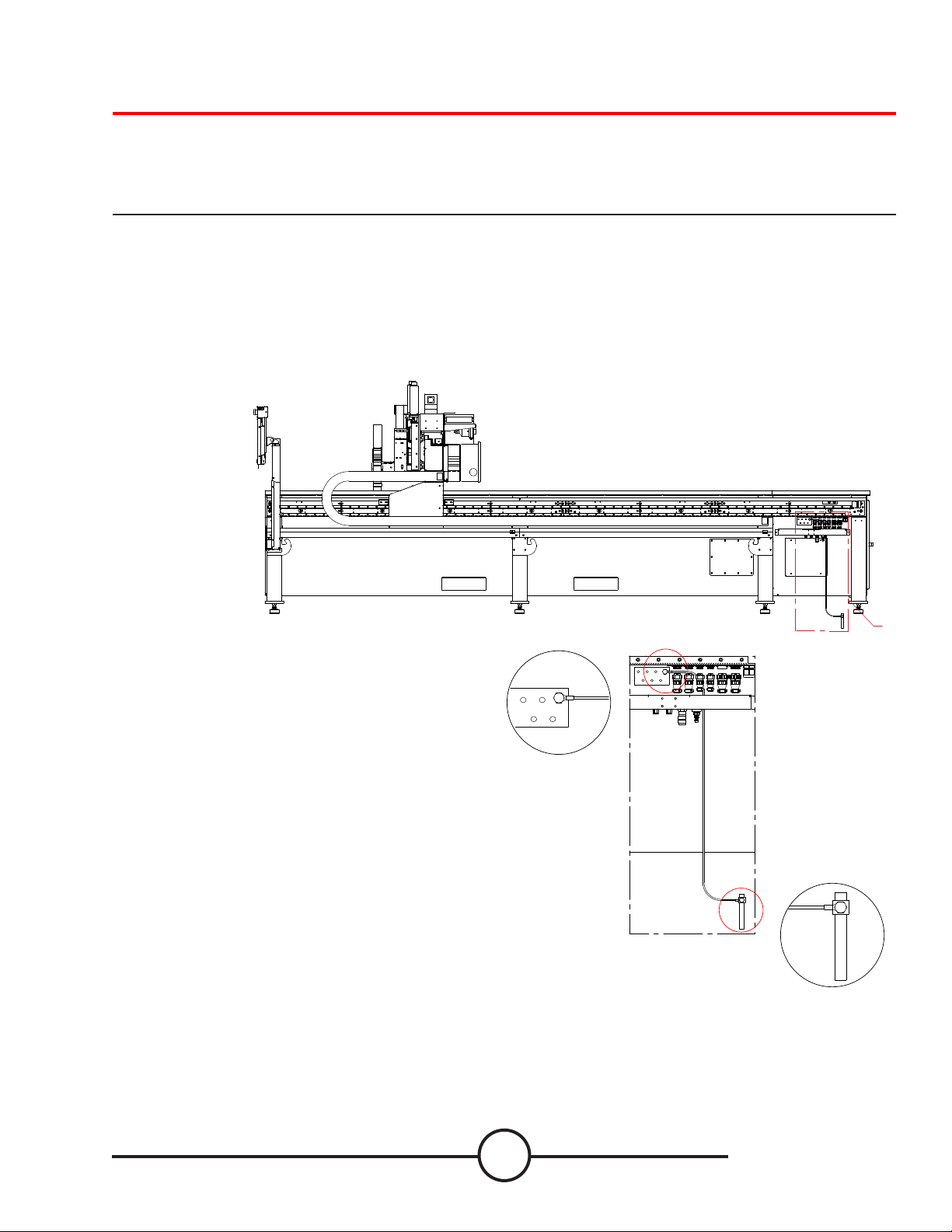
Machine Size
• 60˝ x 120” (1524mm x 3048mm) Cutting Area
• 113.5˝ x 167” (2895.6mm x 4241.8mm) Footprint
Traverse Speed
• 1,500 ipm (0.635 mps)
Cut Speed
• Up to 1500 ipm
Plate Capacity
• Holds Up To 4” (102mm) 5’x10’ (1524mm x 3048mm) Mild Steel
Weight
• 6,600 lbs
Operating Temperature
• 32-104° Fahrenheit (0-40° Celsius)
Motors
• Servo Motors Fitted with Rotary Glass Encoders
Drive System
• Helical Gear Rack and Hardened Pinion with Lubrication
System
Linear Guidance
• Prole Linear Rail
Acceleration Rate
• 0.08g (0.06g Bevel)
Deceleration Rate
• 0.08g (0.06g Bevel)
Input Pneumatics
• Minimum 115PSI Supply Pressure
• Volume - 7 SCFM (420 SCFH) @ 90PSI
Height Control
• Ohmic Sensing
• Automatic Torch Height Control
• 6.75” Z-axis Travel
Bevel Capabilities
• +/-45° Rotation (dependent on material thickness and power
supply conguration)
Software
• Easy-To-Use Lincoln Electric User Interface
• CAM with Irregular Part Nesting
• Popular Shape Library
Fume Extraction (Optional Accessory)
• 61,801 ft3/hr or 1,750 m3/hr minimum
• Automatic Filter Cleaning, Pressure Controlled
Downdraft Conguration
• Multiple Zones Controlled By Motion Controller
Safety
• Dual-Channel Safety System Supporting Emergency Stop
Switch
• Safety System Extended To External Peripherals
• External Drive Power On Switch
Warranty
• *1 Year Warranty
TORCHMATE 5100 CNC PLASMA SYSTEMS FlexCut 125 FlexCut 200 Spirit ii 275 Spirit ii 400
PRODUCTION CUTTING CAPACITY
Mild Steel 1” (25mm) 1.25” 1.5” (38mm) 2” (50mm)
Stainless Steel 3/4”(20mm) 3/4”(20mm) 1” (25mm) 1.5” (38mm)
Aluminum 5/8”(16mm) 3/4”(20mm) 3/4” (20mm) 1.5” (38mm)
CUTTING SPEED @ RATED OUTPUT CURRENT
1/4” MS 210 ipm @125A 200 ipm @200A 230 ipm @200A 230 ipm @ 200A
1/2” MS 88 ipm @125A 110 ipm @200A 125 ipm @ 275A 160 ipm @ 400A
1” MS 32 ipm @125A 40 ipm @200A 65 ipm @275A 85 ipm @ 400A
PROCESS AMPS 20A - 125A 15A - 200A 30A - 275A 30A - 400A
CUTTING GAS
Mild Steel Air / Air Air / Air Oxygen / Air Oxygen / Air Oxygen / Oxygen
Stainless Steel Air / Air Nitrogen Air / Air Nitrogen Air / Air - Nitrogen H17 / Nitrogen Nitrogen / Air
Aluminum Air / Air Air / Air Air / Nitrogen Nitrogen Air
INPUT VOLTAGE 380/400/415V3Ph50/60Hz 380/460/575V3Ph50/60Hz 380V 3Ph 50/60Hz | 400V 3Ph 50/60 Hz
460V 3Ph 50/60Hz 400V3Ph 50Hz (CE) 415V 3Ph 50/60Hz | 440V 3Ph 50/60Hz
575V 3Ph 50/60Hz 480V 3Ph 50/60Hz | 600V 3Ph 50/60 Hz
Table Specications

The business of The Lincoln Electric Company is manufacturing and
selling high quality welding equipment, consumables, and cutting
equipment. Our challenge is to meet the needs of our customers and
to exceed their expectations. On occasion, purchasers may ask
Lincoln Electric Cutting Systems for advice or information about their
use of our products. We respond to our customers based on the best
information in our possession at that time. Lincoln Electric Cutting
Systems is not in a position to warrant or guarantee such advice, and
assumes no liability, with respect to such information or advice. We
expressly disclaim any warranty of any kind, including any warranty
of tness for any customer’s particular purpose, with respect to such
information or advice. As a matter of practical consideration, we also
cannot assume any responsibility for updating or correcting any such
information or advice once it has been given, nor does the provision
of information or advice create, expand or alter any warranty with
respect to the sale of our products.
Lincoln Electric Cutting Systems is a responsive manufacturer, but the
selection and use of specic products sold by Lincoln Electric Cutting
Systems is solely within the control of, and remains the sole respon-
sibility of the customer. Many variables beyond the control of Lincoln
Electric Cutting Systems aect the results obtained in applying these
types of fabrication methods and service requirements.
Subject to Change – This information is accurate to the best of our
knowledge at the time of printing. Please refer to
www.torchmate.com for any updated information.
Customer Assistance Policy
1170 Trademark Suite 101 • Reno, NV • 89521 • U.S.A
Phone: +1.775.673-2200 • www.torchmate.com
US70-040819-MA-01-03
Other manuals for Torchmate 5100 Series
3
Table of contents
Other Lincoln Electric Cutter manuals

Lincoln Electric
Lincoln Electric P07085005NG Mounting instructions

Lincoln Electric
Lincoln Electric MASTERPIPE Mini Profiler Operating instructions

Lincoln Electric
Lincoln Electric OPTITOME2 HPC III User manual

Lincoln Electric
Lincoln Electric OPTITOME II Series Mounting instructions

Lincoln Electric
Lincoln Electric Growth Series User manual

Lincoln Electric
Lincoln Electric LINC-CUT S 1020w User manual

Lincoln Electric
Lincoln Electric PRO-CUT 60 User manual

Lincoln Electric
Lincoln Electric Torchmate 5100 Series User manual

Lincoln Electric
Lincoln Electric Torchmate 4400 User manual

Lincoln Electric
Lincoln Electric Torchmate 5100 Series User manual