User Manual
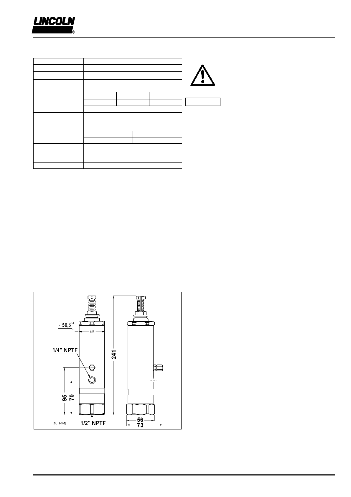
Centro-Matic Injector SL-11 4.2A-68381-C01
Page 5 of 6
Injector No. 85497 Ser. B
Subject to change
LINCOLN GmbH
∗
Postfach 1263
∗
D-69183 Walldorf
∗
Fax 06227/33259 ∗Tel 06227/330
6. Repair
Repairs must be carried out by qualified, trained personnel
only. Warning
Do not disassemble injectors when pump/central
lubrication system are pressurized.
Before performing any works the machine must be out of
operation.
Before servicing shut off pump/central lubrication system and
perform pressure relief procedure. Depressurize pump and
supply line system.
Always collect lubricant in a can.
Only use original replacement parts.
Use all parts included in a kit when replacing parts.
See service parts list for repair kits.
After repair of injectors:
−Check function of injectors.
After repair, before restart of normal operation of the
machine/central lubrication system:
−Adjust output of the relevant injectors as described.
Vent lubrication line system and check function of the central
lubrication system.
Required tools
Open-end wrenches 7/16“, 5/8“, 3/4“ and 2“.
Cylindrical brass or wooden dowel rod 11-12,5 mm & 5 mm
and a steel driver of approx. 3 mm Ø.
Note
The numbers in bold brackets ( ) refer to the item numbers in
the service parts drawing & parts list of the injector.
Disassembly of the Injector
1. Remove the adjustment adapter (3) from the top of the
injector.
2. Remove the piston assembly (8) from inside the injector.
3. Remove plunger spring (9) and spacer (17) from inside the
injector.
4. Remove the inlet adapter (16) from the bottom of the
injector.
5. To remove the slide valve assembly (11), turn injector
over, with the top pointing down. If the slide valve does not
fall out, it may be pushed out of the slide valve body with a
blunt object, being careful not to damage the slide valve
body.
6. To remove valve body (14) including O-rings and back-up
rings:
a) If it sticks in the inlet adapter (16),
gently pry the valve body out of the inlet adapter using a
small round rod. Place the rod into a hole in the side of the
valve body (14) and pry against the face of the inlet
adapter. Work one hole at a time, working around the
valve body until it is freed.
b) If the valve body sticks in the injector body (15),
turn injector right side up and use a 11-12,5 mm Øbrass or
wooden dowel to gently tap the valve body out of the
injector body.
7. Remove back-up rings and O-rings (12 & 13) from the
valve body (14).
8. Remove adjusting screw (1) from adjustment adapter (3).
9. To remove the indicator stem packing (6) from the
adjustment adapter (3), use a blunt object, such as a
wooden dowel, placed into the adjustment screw hole to
gently push the washer (5) and stem packing (6) out of the
adjustment adapter, from the bottom side.
Reassembly instructions
Note: Clean all injector components, and carefully inspect
all parts for wear, replacing parts as necessary.
Generally replace all gasket and seals after a complete
disassembly of the injector.
Apply a liberal coating of lubricant to seals, piston, valve
piston and threaded parts on reassembly of the injector.
Adhere to torque specifications for tightening adjustment
adapter (3) and inlet adapter (16).
ÞSee service parts drawing.
1. Start reassembly by pre-assembling the valve body
(14), by installing the O-rings (13) and back-up rings (12).
See valve body detail, for correct assembly sequence.
Apply a liberal amount of grease to O-rings on outside of
valve body, and gently push the pre-assembled valve body
into the inlet of adapter (16).
2. Install O-ring (4) onto the inlet adapter (16). Install inlet
adapter into the injector body (15), and tighten by hand
assuring that the valve body (14) slides into it´s respective
bore in the injector body. Tighten the inlet adapter to the
injector body, observing the specified torque.
3. Apply a liberal coating of grease to the slide valve
assembly (11). Insert the slide valve assembly through the
top of the injector into the valve body (14), which should
already be installed into the bottom of the injector body.
4. Apply a liberal coating of grease to the piston bore in the
injector body (15). Drop in the plunger spring (9) and place
the spacer (17) inside the spring.
5. Install the O-ring (7) on the piston assembly (8). Apply a
liberal coating of grease to the piston, O-ring and indicator
rod. Place the piston assembly into the piston bore of the
injector body (15).
6. Install the O-ring (4) on adjustment adapter (3).
7. Install washer (5) and packing (6) into adjustment adapter
(3). Apply grease to the O-ring on the adjustment adapter
and the mating bore on the top of the injector body.
Carefully slide the pre-assembled adjustment adapter over
indicator pin down and screw both parts (3 & 15) together
hand tight.
8. Then tighten adjustment adapter (3) with wrench,
observing the specified torque.
9. Reinstall lock nut (2) and screw adjusting screw (1) into
the adjustment adapter (3).
For installation of injector in central lubrication system and
output adjustment of the injector:
ÞSee sections 4. and 5. of the operating instructions.
Please always note specific instructions and safety
instructions of the machine manufacturer on installation and
start-up.