Page Number - 3
CENTRO-MATIC® PUMP, MODEL 85219, 85220
Form 403228
INSTALLING THE PUMP
Place the unit in the approximate location making sure that
electric and hydraulic power connections are accessible.
ark center locations of the four holes at the bottom of the
reservoir. Then drill four 5/8 (16 mm) holes. The use of
1/2 (13 mm) bolts will offer some flexibility in securing the
reservoir to the equipment.
Lubricant outlet of pump should be connected to system with
suitable hose capable of 3,500 PSI (241 bar) working
pressure. Hydraulic inlet connection should be made with at
least 3/8 (9 mm) I. D. hose capable of at least 3,000 PSI (207
bar) operating pressure. Hydraulic return to tank connection
line should be 3/4 (19 mm) I. D. hose or pipe.
Please refer to the 85481 operation manual, section C8, page
269, series B for setting the pump pressure and flow
control.
PUTTING PUMP INTO OPERATION
Filling eservoir
To bulk fill the reservoir, remove the lower and upper pipe
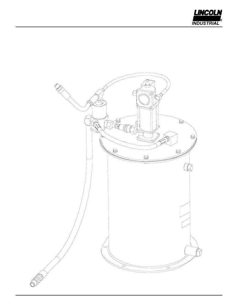
plugs from the side of the reservoir (see Figure 4). Attach the
appropriate bulk-filling pump to the lower inlet (3/4 NPT). Fill
reservoir until grease appears at the top 1/2 NPT vent high
level port. Remove the bulk-filling pump. Replace both pipe
plugs.
Each part is identified with a number keyed to the
matching part on the illustrated views.
General recommendations of tools required are also
specified in each step.
Pay particular attention to the Warning statements to
prevent personal injury and possible damage to pump
components.
Outlet Check Service
(See Figures 1, 2, 9 & 10, Pages 4, 5 & 6)
The pump will not build up sufficient lubricant pressure if the
outlet check (42) is fouled. Foreign material may lodge
beneath the Check Ball (21) or between check disc (17) and
the seat of bushing assembly (18). Sealing surfaces of the
seat must form a perfect seal. Clean parts or replace if
pitted, worn or scored.
1. Turn off and disconnect the hydraulic and electric power
supply to the pump assembly.
2. Standard tools required are a bench mounted vice, a set of
open end wrenches ranging from 7/16 to 1-1/2, a large
24 (600 mm) adjustable wrench and a smaller 10
(254 mm) adjustable wrench.
3. Remove bolts and lock washers (47 & 48 ).
4. Loosen adapter union. Set vent valve assembly to
the side.
5. Remove entire outlet check assembly (42) by loosening
adapter (41) from pump outlet.
6. Remove adapter (41) from outlet check assembly (42).
7. Remove outlet connector (22) from bushing (18).
8. Remove ball check seat (19) from outlet connector (22).
9. Inspect all check components (17, 18, 19, 21) for presence
of foreign material, scoring and or other damage, which
may cause internal leakage. Replace components if
damage is found.
10. If foreign material is present, clean components and
reassemble. Be sure to always replace gaskets (16) &
(20) whenever vent valve is disassembled. Reverse the
above procedure to reassemble. Torque check
assembly to 100 ft.-lbs. (13.5 N- ).
Vent Valve Service (See Figures 3, 9 & 10
Pages 5 & 6)
1. Turn off and disconnect the hydraulic and electrical power
supply to the pump assembly.
2. Standard tools required are a bench mounted vice, a set of
open end wrenches ranging from 7/16 to 1-1/2, a large
24 (600 mm) adjustable wrench and a smaller 10
(254 mm) adjustable wrench.
3. Loosen Adapter Union (43) and Vent Hose (14).
4. Remove bolts and lock washers (47 & 48). Remove vent
valve.
5. Hold base of vent valve in vice to remove elbows (12 & 15).
Turn vent valve in vice so that vice jaws are gripping flats
machined on base of vent valve.
6. Remove hydraulic cylinder (23). Remove piston and
packing (24) from cylinder. If oil leakage was evident
from side of hydraulic cylinder then replace packing.
When filling the reservoir, caution should be used as
extreme pressure can cause damage to the reservoir or
serious personal injury.
MAINTENANCE & REPAIR
General Maintenance
Keep area around pump clean. Clean off filling port area
prior to filling reservoir. Clean area around filler after filling
as lubricants will attract dirt.
Keep lubricants clean and free of dirt and debris.
When replacing grease pails be especially careful to
prevent any foreign matter from entering the grease pail or
contaminating the grease, as it adheres to the pump.
In Case of System Malfunction
(See Trouble Shooting Chart Page 8)
Use the Trouble Shooting Chart to determine where to
look if problems occur.
See the sections below for replacement and repair of
specific areas of the check valve, vent valve or safety
unloader valve.

