7/14
MAINTENANCE AND INSPECTIONS
Fire dampers and control mechanisms do not require routine main-
tenance.
Extraordinary maintenance (repairs) and periodic inspection opera-
tions are the responsibility of the ventilation system operator.
It is recommended to keep enough space (about 200mm) for using
or replacing the control mechanism or for maintenance. Also provide
the necessary space to remove the ventilation duct from the damper
whenever necessary.
It is recommended to provide inspection hatches on both sides of
the ducts connected to the re damper.
The implementation of a periodic inspection plan allows to guaran-
tee the eciency and functionality of the re dampers for the re
safety of the building.
Periodic inspection and cleaning
Periodic inspection shall be performed in accordance with the re-
quirements of the law or by the building regulations or other local
regulations.
In the absence of specic regulations (or to their complement), in ac-
cordance with point 8.3 of the EN 1560 standard, it is recommended
to carry out the following control activities at intervals of no more
than 12 months:
• Check the servomotor electrical wiring for damage (where appli-
cable);
• Check end-switch wiring for damage (where applicable);
• Check damper cleanliness and clean where necessary;
• Check the condition of blades and seals, rectify and report where
necessary;
• Check the correct opening and closing of the re damper by ma-
nual operation according to the instructions in the technical ma-
nual of the re damper;
• Check the opening and closing operation of the damper control-
led by the re alarm system (if present);
• Check the operation of the end switches in open and closed state,
adjust and report if necessary;
• Conrm that the damper fulls its function as part of the control
system (where necessary);
• Check that the damper is left in its normal operating position, whi-
ch usually corresponds to the open position.
Repair
For safety reasons, repair activities involving re-ghting componen-
ts must be carried out only by qualied personnel.
Only original spare parts supplied by the re damper manufacturer
must be used.
A functional test must be performed after each repair.
.
At the end of the inspection, cleaning or repair operations, check that
the re damper is in the normal operating position.
Keep records of all inspections, repair activities, any problems en-
countered and their resolution.
This practice, even when not mandatory, is very useful in practice.
Disposal
Disposal in case of destruction must be carried out in accordance
with national legislation. For electrical and electronic parts also refer
to EU Directive 2011/65.
INSTALLATION
The sizes shown are in mm.
It is recommended to perform a functional test before Installation to
exclude possible damage during transport and another test imme-
diately after installation to exclude accidental damage to the product
and interference with mounting components.
Blade rotation axis positioning
The re damper can be installed with the blade axis positioned verti-
cally or horizontally or tilted at any angle.
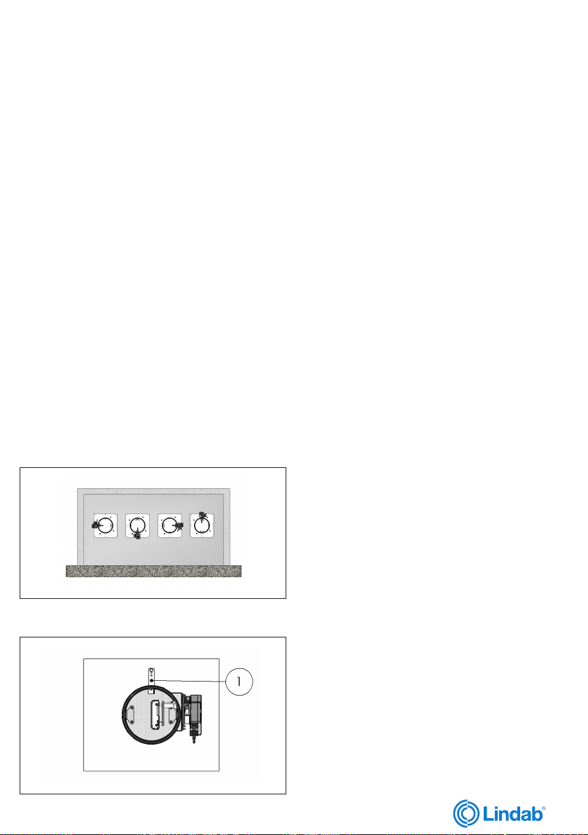
Positioning brackets before xing
1. Positioning brackets
Installation of exible connectors in order to balance out the
ventilation ducts expansion
ATTENTION: the following indications must be considered
binding only if legislation or local regulation where the re
dampers are installed require the use of exible connectors.
Flexible connectors compensate any duct thermal expansion and
wall bending in case of re.
Flexible connectors are used to limit re damper stresses due to ex-
ternal forces in case of re and to preserve re resistance class.
In general it is always appropriate the use of exible connectors for
the followings installations:
– light walls;
– Plasterboard and rock wool or Fire Batt (Weichschott) sealing;
– Applique xing system.
Flexible connector must be normal ammability and in case of re
the grounding bonding should disconnet to guarantee the comple-
te separation between re damper and connected air duct.
When exible connectors made of conductive material (e.g. alumi-
num) are used, no additional grounding bonding is required.
Despite exible connector installation, the re damper must be in-
stalled in the construction support so that its weight does not aect
damper’s installation position both during normal operation and in
case of re.
It is recommended not to compress exible connectors in the in-
stallation phase.
Flexible connector must be at least 100mm long and in order that
possible duct thermal expansions are balanced.
Take care that the exible connector does not interfere with opening
/ closing movement of the blade.
Transfer Application (application not connected to air ducts on
one or both sides)
Note: For this application please refer to national legislation to verify
if any specic obligation is required.
Following tests performed as per EN 1366-2, section 6.3.6 Standard,
it is possible to install the re damper free from air duct from one or
both sides.
• Attention: re resistance classication for transfer application is
conform to section Fire resistance classication according to EN
13501-3-2009 limited to EI 90S if the ducted classication is higher.
rev 20-10
7
We reserve the right to make changes without prior notice