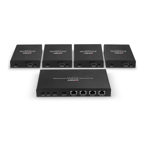
Lindy 38143 User manual

© LINDY ELECTRONICS LIMITED & LINDY-ELEKTRONIK GMBH - FOURTH EDITION (August 2018)
HDMI & IR CAT6 Extender 4x4 Matrix, 50m
User Manual English
Benutzerhandbuch Deutsch
Manuel Utilisateur Français
Manuale Italiano
No. 38143
www.lindy.com
Tested to Comply with
FCC Standards
For Home and Office Use!


User Manual English
Introduction
The LINDY HDMI & IR CAT6 Extender 4x4 Matrix supports the transmission of high definition video
(resolutions up to 1080pFull HD and 1920×1200@60Hz, including 1080p 3D*), multi-channel digital audio
and control via push button, IR, RS-232 and TCP/IP from four high definition sources to four remote
displays over a single CAT. 6 cable of up to 50m* for each output. Each of the 4 outputs is also
simultaneously mirrored on local HDMI output ports, perfect for monitoring outputs or for the creation of a
secondary local zone.
*Please Note: The quoted lengths and resolutions are possible with a direct connection between
Transmitter and Receiver using good quality Cat.6 solid core cable. Using a different cable type, or
introducing wall plates, couplers or patch panels will result in a reduction of possible distances.
It supports high resolution digital audio formats such as LPCM 7.1 CH, Dolby TrueHD, Dolby Digital Plus
and DTS-HD Master Audio as well as 3D content that can be displayed when connecting a 3DTV and 3D
source.
This flexible feature rich product has been designed to be used in a number of different applications, such
as:
Domestic HDMI Matrix system
Video/TV wall display and control
Security surveillance and control
Commercial advertising, display and control
University Lecture hall display and control
Retail Sales and demonstration
Package Contents
HDMI & IR CAT6 Extender 4x4 Matrix
4 x HDMI & IR CAT6 Receivers
12V DC 2.5A Multi County PSU (with Euro, US, UK & Australian/China AC connectors)
4 x 5V DC 1A Multi County PSU (with Euro, US, UK & Australian/China AC connectors)
4 x IR Emitter with 3.5mm connector
5 x IR Receiver with 3.5mm connector
4 x IR Remote Control (with CR2025 battery)
RS-232 9 Pin Male/Female Cable
Mounting Ears & Screws
This Manual
Specification
Extends HDMI 1.4 & IR signals via CAT. 6 UTP Cable
Supports resolutions: 1080p24/30/50/60, 1080i, 720p, 576p, 480p
4K 30Hz is only supported by EDID setting/cloning on local HDMI output ports
Support for 3D Signals, including 1080p 3D according to HDMI 1.4
Deep Colour capable: supports 30/36/48 bit colour depth
Audio Formats: LPCM, DTS Digital, DTS HD, Dolby Digital & Dolby True HD
Supports 20 –60kHz IR Frequencies (Bi-directional: Rx to Tx or Tx to Rx)
Maximum HDMI Cable length, 5m in/out
Preset or Cloned EDID can be used independently on each port
Each Output (A-D) supports simultaneous output over HDMI & CAT6
Transmitter/Matrix ports: 4 x HDMI Type A In, 4 x HDMI Type A Out, 4 x CAT6 Out, 4 x 3.5mm IR In, 4
x 3.5mm IR Out, IR Ext In 3.5mm, DC Socket, RS232 & RJ45 (TCP/IP)
Receiver ports: HDMI Type A Out, 1x CAT6 In, 3.5mm IR In, 3.5mm IR Out, Coaxial SPDIF Out & DC
Socket
Supports RS-232, remote control, on-panel control and TCP/IP Control
Power consumption: 23W Maximum, 0.5W standby

User Manual English
Overview
Front Panel
1. LCM
Display’s the current Input/Output status and can be used to view the EDID Management Window
2. IR Window / Power / Lock
IR Window –Receives commands from the supplied IR Remote Control
Power –Use to switch the Matrix On (LED illuminates Green) or to Standby (LED illuminates Red)
Lock –Press to Lock all other buttons on the front panel, press again to unlock.
3. Output/Input
Press one of the Output A –D or All buttons and then press Input 1 –4 to select which Input to display
Press PTP to reset the Input/Output combination to A1, B2, C3 and D4.
4. EDID
Configure which EDID is used for each input port
Rear Ports
1. PC Control
TCP/IP: Connect the Matrix to an Ethernet network to allow it to be controlled by a PC/Controller on
the network
RS-232: Connect a PC/Controller to the Matrix using a 9 Way RS-232 cable
2. IR Ports
IR Output: Ports 1 –4 control the HDMI Equipment on the corresponding HDMI Input port
IR Input: Ports 1 –4 control the HDMI Display connected to the Receiver using the corresponding
CAT. 6 Output port
IR Ext: Allows the IR port used to control the matrix to be extended

User Manual English
3. HDMI Inputs 1 –4
Connect 4 HDMI Source devices, such as Bluray Player, Media Streaming Box or Satellite STB
4. CAT. 6 & HDMI Outputs A –D
Connect to the 4 Receiver units via CAT. 6 Cable and 4 local HDMI Displays. Each Output A –D is
mirrored to a CAT. 6 Receiver and HDMI Display.
5. DC Power
Connect the supplied 12V power supply
CAT. 6 Receiver
1. HDMI Out
Connect a Display using a HDMI cable of up to 5m
2. Power LED
Illuminates when the device is powered on
3. Lock LED
Illuminates when a HDMI signal is being transmitted
4. Coaxial Out
Connect to an Amplifier or Active Speakers using coaxial cable
5. ARC Switch
Select On to send audio from your Display’s ARC channel to the Receiver’s Coaxial Out port, select
Off to use the audio from the selected HDMI Input of the Matrix.
6. DC Power
Connect the supplied 5V power supply
7. IR RX
Connect an IR Receiver to control the current HDMI source being viewed via the Matrix
8. IR TX
Connect an IR Emitter to allow your HDMI Display to be controlled remotely from the Matrix
9. CAT. 6 In
Connect a CAT. 6 cable of up to 50m between this port and a CAT. 6 Output port on the Matrix

User Manual English
IR Receiver & Emitter
IR Receiver (RX)
To control a HDMI source plug the IR Receiver into the IR RX port of the CAT. 6 Receiver unit. Place the
IR Receiver on or near your display.
To control a display plug an IR Receiver into the corresponding IR input port of the Matrix unit. Place the
IR Receiver in a position where it is able to receive remote signals.
IR BLASTER (TX)
To control a display plug the IR Emitter into the IR TX port of the CAT. 6 Receiver unit. Place the Emitter
in front of the IR eye of the display.
To control a HDMI source plug an IR Emitter into the corresponding IR output port of the Matrix unit.
Place the Emitter in front of the IR eye of the source.
Installation
1. Connect up to 4 sources such as a Blu-Ray Player, Digital Signage Player, A/V Receiver, Cable or
Satellite Receiver, etc. to the HDMI inputs on the unit using HDMI cables of up to 5m in length.
Important! Do not hot plug devices! Insert and remove cables carefully with the power SWITCHED
OFF. Connecting/disconnecting while the unit is powered can result in damage to Matrix’s circuitry.
2. Connect the output UTP ports to the CAT. 6 Receiver using good quality CAT. 6 UTP cables no longer
than 50m. Displays can also be connecteddirectly to the corresponding HDMI output ports using HDMI
cables of up to 5m in length. If you require a longer cable please use a LINDY Active HDMI Cable or
a LINDY HDMI Extender.
3. Plug in IR Emitters to the back of the Matrix unit (IR output ports), the IR Emitters are labelled IR TX,
place the eye in front of the IR receiver of the source.
4. Plug in IR Receivers to the IR RX port of the CAT. 6 Receiver’s, the IR Receivers are labelled IR RX,
place the IR Receivers in a location that will receive a remote signal.
5. Plug in and power on all sources first, followed by the Matrix unit (power supply included), followed by
the display receivers, followed by each of the Displays.
At this point each display connected should display the assigned source (Input 1 at default when powered
on initially). Scroll through each of the sources on each display to ensure everything is in working order.
Use the included IR remote at each display receiver to test switching function between sources and IR
function itself.

User Manual English
Operation
EDID
The Matrix is capable of using either preset or cloned EDID
data to ensure maximum compatibility. The table shows the
different EDID values which can be set using the Matrix’s
front panel buttons or using the supplied software via RS-
232 or TCP/IP.
Using the buttons on the front of the Matrix, press Menu to
enter the EDID Management Window. Press Up or Down
until you get to the EDID value which you want to set and
then press Enter. Now use Up or Down to scroll to the Input
you want to apply the EDID to and then press Enter again.
IR Control
The Matrix supports bi-directional IR signal extension, allowing control of the HDMI sources remotely from
the Receiver and displays remotely from the Matrix, simply install the supplied IR Receivers and Emitters
according to your requirement.
Each of the IR TX ports (1 –4) located on the back of the Matrix unit is allocated to the corresponding
HDMI Input (1 –4), this allows you to control whichever HDMI source you are viewing from a remote
location even after switching between inputs.
Each of the IR RX ports (1 –4) located on the back of the Matrix unit is allocated to the corresponding
HDMI Input (1 –4), this allows you to control the HDMI display(s) currently using this Input.
Please Note: Misplaced or poorly secured IR Emitters and Receivers may result in intermittent IR control
signals passed to and from the matrix. Check your placement and adjust if necessary.
PC Controller
The Matrix can be controlled by a Windows PC connected via RS-232 (9 Way) cable or via a LAN using
TCP/IP.
Begin by connecting the PC and Matrix by your preferred method and then switch the Matrix on.
Download the latest version of MatrixController.exe from www.lindy.com and then open it by double
clicking on it.
When you open the software you will be presented with the screens shown on the following page, you
can now begin to configure the Matrix according to your requirement.
EDID Mode
EDID Description
1
1080i, 2CH AUDIO
2
1080i, DOLBY/DTS 5.1
3
1080i, HD AUDIO
4
1080p, 2CH AUDIO
5
1080p, DOLBY/DTS 5.1
6
1080p, HD AUDIO
7
3D,1080p, 2CH AUDIO
8
3D, 1080p,DOLBY/DTS 5.1
9
3D,1080p, HD AUDIO
10
4k*2k, 2CH AUDIO
11
4k*2k, DOLBY/DTS 5.1
12
4k*2k, HD AUDIO
13
DVI 1024x768
14
DVI 1920X1080
15
DVI 1920X1200
16
Copy from HDMI OUTPUT A
17
Copy from HDMI OUTPUT B
18
Copy from HDMI OUTPUT C
19
Copy from HDMI OUTPUT D

User Manual English
General
1. Select RS-232 COM or TCP Control Mode
2. Select RS-232 COM Port
3. Click to Connect/Disconnect from the Matrix
(COM Mode)
4. Select the Matrix IP address
5. Click to Connect/Disconnect from the Matrix
(TCP Mode)
6. Search Matrix IP address
7. Configure the Matrix’ IP & MAC address’
8. Click to Factory Reset the Matrix
9. Device Information display area
10. Click to Refresh Device Information and
Input/Output settings (Matrix tab)
11. Click to Clear Device Information
12. Enable/Disable the Matrix’ Beep function
TCP Configuration
After clicking button 7 you will be presented with
the TCP Configuration menu:
1. Choose from Auto (DHCP) or Static IP
2. Enter the Matrix IP address (Static IP only)
3. Enter the MAC address of the Matrix
EDID
The Matrix has 3 methods to set the EDID mode.
Set mode, Copy mode and Open EDID mode.
1. Set Mode: Select the required EDID from the
drop down menu, choose an Input and finally
click Set.
2. Copy Mode: Select which Output you want to
copy the EDID from, then choose an Input
and finally click Set.
3. Open EDID Mode: Click the folder and
navigate to the location where you have
saved the EDID File. Select the file, then
choose an Input and finally click Set.
4. Click the status button to refresh Input/EDID
status

User Manual English
Matrix
The Matrix menu allows you to easily set the
Input/Output combination you require using a simple
graphical interface, simply set the Input value for
each Output individually.
1. Displays which Input is being used on each
Output
2. Click to select an Input for that Output
3. Click to select the previous or next Input for that Output
FW Upgrade
Please contact LINDY support for information on upgrading the Firmware of this product.
Trouble Shooting
Check that the HDMI source and display are both powered on and active.
Power off all the devices, then power on in this order: first, the HDMI source(s), followed by the Matrix
Unit, then the Receiver units and finally the display(s).
Please check all cable and power supply connections are made correctly
Please check that the dip switches on the side of the receivers are set to the correct setting for the
length of CAT. 6 cable you are using.
Check that the Lock LED is illuminated, if it is not please try a shorter or better quality CAT. 6 UTP
cable
If the Lock LED is illuminated and no picture is received please try a different HDMI Input on the Matrix.
If this is successful please use the same EDID setting for both of these inputs and then retry.

Benutzerhandbuch Deutsch
Einführung
Die LINDY HDMI & IR Cat.6 Extender 4x4-Matrix unterstützt die Übertragung von High Definition Video
mit Auflösungen bis zu 1080p Full HD und 1920×1200@60Hz, einschließlich 1080p 3D, digitales
Mehrkanal-Audio und Steuerung über Gerätetasten, IR, RS-232 und TCP/IP. Signale aus vier HDMI-
Quellen können unabhängig auf vier Ausgänge geschaltet werden. Jeder Ausgang verfügt parallel über
eine HDMI Buchse für einen lokalen Monitor sowie über RJ45 Ausgänge zu vier remote-Displays über
Cat.6 Kabel bis 50m* für jeden Ausgang.
Unterstützt werden digitale Audioformate wie LPCM 7.1 CH, Dolby TrueHD, Dolby Digital Plus und DTS-
HD Master Audio.
*Hinweis: Die angegebenen Distanzen und Auflösungen erreichen Sie mittels hochwertiger Cat.6 Solid
Core Kabel und einer direkten Verbindung zwischen Sender- und Empfängereinheit. Die Nutzung eines
anderen Kabeltyps, der Einsatz von Wanddosen, Kupplungen oder Patchfelder kann die maximal
erreichbare Distanz beeinflussen.
Lieferumfang
HDMI & IR Cat.6 Extender 4x4 Matrix
4 x HDMI & IR Cat.6 Receiver
12V DC 2.5A Multi County Netzteil (mit Euro, US, UK & Australien/China AC Wechselsteckern)
4 x 5V DC 1A Multi County Netzteil (mit Euro, US, UK & Australien/China AC Wechselsteckern)
4 x IR Emitterkabel mit 3.5mm Stecker
5 x IR Receiverkabel mit 3.5mm Stecker
4 x IR Fernbedienung (mit CR2025 Batterie)
RS232 Kabel D9 Stecker/Kupplung
19” Montagewinkel und Schrauben
Dieses Handbuch
Spezifikationen
Der Extenderteil überträgt HDMI 1.3 & IR Signale über Cat.6 Kabel
Unterstützte Auflösungen: 1080p24/30/50/60, 1080i, 720p, 576p, 480p
4K 30Hz wird unterstützt nach Kopieren der EDID Monitordaten an den lokalen HDMI Ausgängen
Unterstützung für 3D Signale, einschließlich 1080p 3D nach HDMI 1.4
Deep Colour: unterstützt 30/36/48 Bit Farbtiefe
Audio Formate: LPCM, DTS Digital, DTS HD, Dolby Digital & Dolby True HD
Unterstützt IR Fernbedienungsfrequenzen 20 –60KHz (Bidirektional: Rx > Tx oder Tx > Rx)
Maximale HDMI Kabellängen 5m in/out
Unterstützt voreingestellte oder kopierte EDID Monitordaten individuell für jeden Port
Jeder Ausgang kann gleichzeitig lokal über HDMI und über Extender ausgegeben werden
Transmitter/Matrix Ports: 4x HDMI Typ A In, 4x HDMI Type A Out, 4x Cat.6 Out, 4x 3.5mm IR In, 4x
3.5mm IR Out, IR Ext In 3.5mm, DC Netzteilanschluss, RS232 & RJ45 (TCP/IP)
Receiver Ports: HDMI Type A Out, 1x Cat.6 In, 3.5mm IR In, 3.5mm IR Out, Coaxial SPDIF Out & DC
Netzteilanschluss
Bedienung via RS-232, IR-Fernbedienung, Gerätetasten und TCP/IP
Leistungsaufnahme : ca. 23W Maximum, 0.5W Standby

Benutzerhandbuch Deutsch
Übersicht
Frontblende
1. LCM - Display
Zeigt den aktuellen Input/Output Status an kann das EDID Management Fenster anzeigen
2. IR Empfängerfenster / Power / Lock
IR Empfängerfenster –hier ist der Empfänger für die IR Fernbedienugn des platziert
Power –Ein/Aus-Schalter (Grün/Ein) oder Standby (Rot)
Lock –Einmal drücken um alle Fronttasten zu sperren, nochmals drücken um sie wieder frei zu geben.
3. Output/Input Wahlschalter
Drücken Sie eine der Output A –D oder die ALL Taste und dann den Input 1 –4 der auf diesen
Ausgängen angezeigt werden soll. Drücken Sie PTP um die Input/Output Kombination auf A1, B2, C3
und D4 umzustellen.
4. EDID
Tastenfeld zur Konfiguration der zu verwendenden EDID Monitoreinstellungen
Rückseiten-
Ports
1. PC Control
TCP/IP: Schließen Sie die Matrix an Ihr Ethernet Netzwerk an für die Steuerung via Netzwerk
RS-232: RS-232 Anschluss für einen Controller oder Steuerrechner via RS-232 Kabel
2. IR Ports
IR Output:Ports 1 –4 Anschluss für die IR Emitterkabel zur Steuerung der HDMI Geräte an den 4
HDMI Eingängen
IR Input:Ports 1 –4 Anschlüsse für die IR Receiverkabel die an den vier zugehörigen HDMI Displays
(HDMI Ausgangsports) die IR Signale aufnehmen können
IR Ext: Anschluss für den IR Sensor der Fernbedienung des Gerätes selber

Benutzerhandbuch Deutsch
3. HDMI Inputs 1 –4
Zum Anschluss der 4 HDMI Signalquellen, z.B. Blu-ray Player, Streaming Box oder Sat Receiver
4. CAT.6 & HDMI Outputs A –D
Anschluss für die vier Receiverboxen über Cat.6 Kabel und für die 4 lokalen HDMI Displays. Jeder
Output A –D ist parallel lokal über HDMI sowie über die Receiverbox aktiv.
5. DC Power
Schließen Sie hier das beiliegende 12V Netzteil an.
Cat.6 Receiver
1. HDMI Out
Anschluss für das HDMI Display, Kabellänge maximal 5m
2. Power LED
Leuchtet bei aktiver Stromversorgung
3. Lock LED
Leuchtet bei synchronisiertem aktiven HDMI Eingangssignal
4. Coaxial Out
Digitaler coaxialer Audioausgang
5. ARC Switch
Wählen Sie ON wenn vom ARC Ausgang Ihres Displays das Audiosignal zum Coaxial Out port des
Receivers übertragen warden soll, OFF für das HDMI Audio-Eingangssignal des Receivers.
6. DC Power
Netzteil Anschluss für das beiliegende 5V Netzteil
7. IR RX
Anschluss für das IR Receiverkabel zur Aufnahme von Fernbedienungssignalen
8. IR TX
Anschluss für das IR Emitterkabel zur Ausgabe von Fernbedienungssignalen
9. Cat.6 In
Anschluss des Cat.6 Kabels zur Matrix

Benutzerhandbuch Deutsch
IR Receiver & Emitter Kabel
IR Receiver (RX)
Verbinden Sie das IR-Receiverkabel mit dem IR RX Port des Cat.6 Receivers um ein HDMI-Quellgerät zu
steuern. Platzieren Sie den Receiver auf oder in naher Umgebung des Displays.
Verbinden Sie das IR-Receiverkabel mit dem entsprechenden IR-Eingangsport (IR Input) der Matrix, um
ein Display zu steuern. Platzieren Sie den Receiver so, dass er Fernbedienungssignale empfangen kann.
IR Blaster / Emitter (TX)
Verbinden Sie das IR-Transmitterkabelmit dem IR TX Port des Cat.6 Receivers um ein Display zu steuern.
Platzieren Sie den Transmitter direkt vor dem IR Empfänger des Displays.
Verbinden Sie das IR-Transmitterkabel mit dem entsprechenden IR Ausgangsport (IR Output) der Matrix,
um eine HDMI-Quelle zu steuern. Platzieren Sie den Transmitter direkt vor dem IR Empfänger der Quelle.
Installation
1. Schließen Sie bis zu 4 HDMI Signalquellen an die Eingangsports an. Die Kabellängen sollten 5m nicht
überschreiten. Falls längere Kabel benötigt werden, nutzen Sie hierfür bitteunsere aktiven HDMI Kabel
oder entsprechende HDMI Extender.
Schalten Sie die HDMI Geräte aus, bevor Sie die Verbindung herstellen.
2. Schließen Sie die Cat.6 Receiver Boxen mit hochwertigen, maximal 50m langen Cat.6 Kabeln an –bei
großen Längen nach Möglichkeit mit starren Installationskabeln.
3. Schließen Sie die HDMI Displays mit maximal 5m langen HDMI Kabeln an.
4. Schließen Sie die IR TX und RX Kabel wie im Abschnitt zuvor beschrieben an (falls benötigt)
5. Schließen Sie alle Netzteile an und schalten Sie alles in der Reihenfolge Signalquellen, Matrix,
Receiver, Displays ein.
Nun sollte jedes Display das zugewiesene Signal anzeigen –Default-Einstellung ist Input 1. Schalten Sie
alle Eingangs- und Ausgangskombinationen durch, um zu prüfen ob alles funktioniert. Verwenden Sie die
Fernbedienung oder die Tasten am Gerät. Beachten Sie die folgenden Hinweise im Kapitel Betrieb.

Benutzerhandbuch Deutsch
Betrieb
EDID –Monitordaten
Die Matrix kann sowohl EDID-Voreinstellungen wie auch
kopierte EDID-Monitordaten verwenden. Die
nebenstehende Tabelle listet die Voreinstellungen auf.
Die Modi können über die Tasten an der Frontblende, oder
unter Verwendung der mitgelieferten Software remote via
RS232 oder Webinterface eingestellt werden.
Zur Bedienung von der Frontblende drücken Sie zuerst die
Menu-Taste, selektieren Sie dann mit den Up/ Down Tasten
den gewünschten Wert und bestätigen Sie die Auswahl mit
der ENTER Taste. Wiederholen Sie den Vorgang für alle
vier Eingänge.
IR Fernbedienungssignale
Die Matrix unterstützt bidirektionale IR Signalübertragung. Dies erlaubt sowohl die Fernsteuerung der
HDMI Quellen wie auch die der Monitore. Installieren Sie die IR TX und RX Kabel einfach an den
gewünschten Orten und den entsprechenden 3,5mm Buchsen.
Jeder der vier IR TX Ports (1-4) ist dem entsprechenden INPUT Port zugeordnet, so dass das IR Signal
immer nur an die mit dem Input Port verbundene Signalquelle ausgegebene wird .
Jedem der vier IR RX Ports (1-4) ist dem entsprechenden OUTPUT Port zugeordnet, das IR RX Kabel
muss bei dem entsprechenden Monitor installiert werden, so dass das IR Signal immer nur an diesem
Monitor aufgenommen wird und zur mit ihm verbundenen HDMI Signalquelle weitergeleitet wird.
ACHTUNG: Schlecht platzierte oder befestigte IR Emitter und Receiver können dazu führen dass die IR
Signale nicht aufgenommen und ausgegeben werden können. Achten Sie daher bitte auf eine sorgfältige
Platzierung und Befestigung.
PC Controller / Remote Steuerung
Die Matrix kann von einem Windows PC über RS232 oder TCP/IP (Ethernet/LAN) ferngesteuert werden.
Schließen Sie den PC über Ihre präferierte Methode an, RS232- oder RJ45-Kabel.
Laden Sie die aktuelle Version der Software MatrixController.exe von unserer Produkt-Webseite auf
www.LINDY.com herunter und öffnen Sie sie durch Doppelklick.
Es öffnet sich das folgende Fenster und Sie können mit der Konfiguration des Switches beginnen.
EDID Mode
EDID Description
1
1080i, 2CH AUDIO
2
1080i, DOLBY/DTS 5.1
3
1080i, HD AUDIO
4
1080p, 2CH AUDIO
5
1080p, DOLBY/DTS 5.1
6
1080p, HD AUDIO
7
3D,1080p, 2CH AUDIO
8
3D, 1080p,DOLBY/DTS 5.1
9
3D,1080p, HD AUDIO
10
4k*2k, 2CH AUDIO
11
4k*2k, DOLBY/DTS 5.1
12
4k*2k, HD AUDIO
13
DVI 1024x768
14
DVI 1920X1080
15
DVI 1920X1200
16
Copy from HDMI OUTPUT A
17
Copy from HDMI OUTPUT B
18
Copy from HDMI OUTPUT C
19
Copy from HDMI OUTPUT D

Benutzerhandbuch Deutsch
Reiter General
1. RS-232 COM oder TCP Control Modus
auswählen
2. RS-232 COM Port auswählen
3. Connect/Disconnect zur Matrix (COM
Modus)
4. IP Adresse der Matrix einstellen
5. Connect/Disconnect zur Matrix (TCP Mode)
6. Suche die IP Adresse der Matrix
7. Konfigurieren der IP & MAC Adresse der
Matrix (siehe auch unten)
8. Die Matrix auf Factory Einstellungen
zurücksetzen
9. Anzeigebereich für Geräteinformationen
10. Refresh für Anzeigebereich und Input/Output Einstellungen durchführen (Matrix Reiter)
11. Geräteinformationen löschen
12. Enable Beep: Den Bestätigungston der Matrix ein-/ausschalten
TCP Konfiguration (7.)
Menüpunkt 7 öffnet das TCP/IP Konfigurationsmenu:
1. Auswahl Auto (DHCP) oder Static IP
2. Eingabe der Matrix IP Adresse (nur bei Static IP)
3. Eingabe der MAC Adresse der Matrix
Reiter EDID Konfiguration
Wählen Sie zwischen den 3 Arten den EDID
Modus zu wählen (Set / Copy / Open).
1. Set Mode: Wählen Sie die passende
Voreinstellung aus der Drop-Down-Liste, den
Input Port, und klicken Sie auf Set
2. Copy Mode: Wählen Sie aus von welchem
lokalen HDMI Ausgangsport die EDID Daten
des dort angeschlossenen Monitors kopiert
werden sollen. Wählen Sie den Input Port auf
den diese Daten kopiert werden sollen und
klicken Sie Set.
3. Open EDID Mode: Wählen Sie eine Datei mit
gespeicherten EDID Daten aus.
4. Ein Klick auf Status zeigt die aktuelle
Zuordnung an.

Benutzerhandbuch Deutsch
Reiter Matrix
Das Matrix Menu erlaubt das Umschalten der
Input/Output Kombinationen über ein GUI.
1. Zeigt den aktuellen Eingangskanal an
2. Wählt einen Eingangskanal aus und schaltet um
3. Schaltet auf den vorherigen oder nächsten
Eingangskanal um
Reiter FW Upgrade
Sollten Sie Probleme mit der Matrix haben so kontaktieren Sie bitte den LINDY Techniksupport. Hier
können Sie gegebenenfalls erfahren ob eine neue Firmware für die Matrix vorliegt.
Problembeseitigung
Prüfen Sie bitte alle Kabelverbindungen auf festen Sitz und die Netzteile auf Funktion. Achten Sie
darauf die Netzteile von Matrix und den Extenderboxen nicht zu vertauschen.
Schalten Sie alle Geräte aus und in folgender Reihenfolge nacheinander wieder ein: zuerst die HDMI
Quellen, dann die Matrix, die Receiver und abschließend die Monitore.
Prüfen Sie ob die HDMI Signalquellen und Displays im Stand alone Betrieb korrekt funktionieren
Wenn einzelne Receiver Boxen nicht funktionieren prüfen Sie bitte zuerst ob der zugehörige lokale
HDMI Ausgang ein Signal liefert. Die Lock LED am Receiver muss leuchten, versuchen Sie es
andernfalls mit einem anderen höherwertigen oder kürzeren Cat.6 Kabel
Wenn die Lock LED am Receiver leuchtet und der Monitor kein Bild ausgibt prüfen Sie bitte die
Kabelverbindung zum Monitor sowie das HDMI Eingangssignal am zugeordneten Input Port.
Wenn bestimmte Input/Output Kombinationen kein Bild zeigen, versuchen Sie bitte die EDID Daten
des Monitors auf den entsprechenden Input zu kopieren. Eventuell liegt hier eine Inkompatibilität der
EDID Daten vor.

Manuel Utilisateur Français
Introduction
L’extender HDMI & IR CAT6 4x4 Matrix LINDY prend en charge la transmission de vidéo en haute
définition (résolutions jusqu’à 1080p Full HD et 1920×1200@60Hz, 1080p 3D inclus*), l’audio multicanal
numérique et le contrôle via boutons sur le boîtier, IR, commandes RS-232 et TCP/IP à partir de quatre
sources hautes définitions vers quatre affichagesdistants via uncâble CAT.6 de jusqu’à 50m*pour chaque
sortie. Chacune des quatre sorties est simultanément dupliquée sur des ports de sorties HDMI locaux,
solution parfaite pour monitorer les sorties ou pour créer une zone secondaire d’affichage.
*Merci de noter : les longueurs et résolutions citées sont possible avec une connexion directe entre
l’émetteur et le récepteur en utilisant un câble CAT.6 monobrin de bonne qualité. L’utilisation d’un type de
câble différent ou l’introduction de connexions intermédiaires comme les prises murales, coupleurs ou
panneaux de brassage peuvent induire une réduction des distances possibles.
Il prend en charge les formats audio numérique haute définition comme LPCM 7.1 CH, Dolby TrueHD,
Dolby Digital Plus et DTS-HD Master Audio, ainsi que les contenus 3D qui pourront être affichées lors de
la connexion de sources 3DTV et 3D. Ce produit aux caractéristiques souples a été conçu pour être utilisé
dans de très nombreuses applications, comme:
Systèmes Matrix HDMI domestique
Affichage et contrôle de murs Vidéo/TV
Systèmes de surveillance et de sécurité
Affichages publicitaire et commerciaux
Affichages et contrôle de salle de conférence
Ventes au détail et démonstration
Contenu de l’emballage
Extender 4x4 Matrix HDMI & IR CAT6
4 x récepteurs HDMI & IR CAT6
Alimentation multi-pays 12V DC 2.5A (avec adaptateurs secteur Euro, US, UK & Australie/Chine)
4 x alimentations multi-pays 5V DC 1A (avec adaptateurs secteur Euro, US, UK & Australie/Chine)
4 x émetteurs IR avec connecteurs jack 3,5mm
5 x récepteurs IR avec connecteurs jack 3,5mm
4 x Télécommande IR (avec pile CR2025)
Câble RS-232 9 pins Mâle/Femelle
Equerre et vis de montage
Ce manuel
Spécifications
Etends les signaux HDMI 1.3 & IR via câble CAT6 UTP
Résolutions prises en charge: 1080p24/30/50/60, 1080i, 720p, 576p, 480p
4K 30Hz uniquement pris en charge en paramétrant/clonant l’EDID sur les ports HDMI de sorties
locaux
Prise en charge des signaux 3D, 1080p 3D inclus en conformité HDMI 1.4
Capacité Deep Colour: prise en charge des profondeurs de couleurs 30/36/48 bit
Formats audio: LPCM, DTS Digital, DTS HD, Dolby Digital & Dolby True HD
Prise en charge des fréquences IR 20 –60KHz (Bidirectionnel: Rx vers Tx ou Tx vers Rx)
Longueur de câble HDMI maximale, 5m entrée/sortie
La présélection ou le clonage EDID peut être utilisé indépendamment sur chaque port
Chaque sortie (A-D) prend en charge la sortie simultanée via HDMI & CAT6
Ports émetteurs (Transmitter)/Matrix: 4 x HDMI Type A In(entrée), 4 x HDMI Type A Out(sortie), 4 x
CAT6 Out, 4 x 3.5mm IR In, 4 x 3.5mm IR Out, IR Ext In 3.5mm, prise DC, RS232 & RJ45 (TCP/IP)
Ports récepteur (Receiver): HDMI Type A Out, 1x CAT6 In, 3.5mm IR In, 3.5mm IR Out, Coaxial SPDIF
Out & prise DC
Prise en charge contrôle via RS-232, télécommande, boutons sur le panneau et TCP/IP
Puissance: 23W Maximum, 0.5W en veille

Manuel Utilisateur Français
Vue d’ensemble
Panneau avant
1. LCM
Affiche le statut actuel Entrée/Sortie et peut être utilisé pour voir la fenêtre de gestion EDID
2. IR Window / Power / Lock
IR Window –reçoit les commandes de la télécommande fournie
Power –utilisé pour démarrer le Matrix (LED verte) ou pour le mettre en veille (LED rouge)
Lock –Appuyez pour bloquer tous les autres boutons du panneau avant, un second appui les libère.
3. Output/Input
Appuyez sur une des sorties (Output) A –D ou tous les boutons et appuyez ensuite sur une entrée
(Input) 1 –4 pour sélectionner l’entrée à afficher
Appuyez sur PTP pour remettre à zéro la combinaison Input/Output sur A1, B2, C3 et D4.
4. EDID
Configure quel EDID est utilisé pour chaque port en entrée
Ports au dos
1. PC Control
TCP/IP: Connectez le Matrix à un réseau Ethernet pour lui permettre d’être contrôlé par un
PC/Contrôleur sur le réseau
RS-232: Connectez un PC/Contrôleur au Matrix en utilisant un câble D9 RS-232
2. IR Ports
IR Output: les ports 1 –4 contrôlent les équipements HDMI sur l’entrée HDMI correspondante
IR Input: les ports 1 –4 contrôlent les affichages HDMI connectés aux récepteurs (Receiver) en
utilisant les ports de sorties CAT.6 correspondant
IR Ext: permet au port IR utilisé pour contrôler le matrix d’être déporté

Manuel Utilisateur Français
3. HDMI Inputs 1 –4
Connecte 4 appareils sources HDMI, comme un lecteur Blu-ray, une box de diffusion de médias ou
un récepteur satellite
4. CAT.6 & HDMI Outputs A –D
Connecte les unités 4 Receiver via câble CAT.6 et 4 affichages HDMI locaux. Chaque sortie (Output)
A –D est dupliquée sur un récepteur CAT.6 et un affichage HDMI.
5. DC Power
Connecte l’alimentation 12V fournie
CAT.6 Receiver
1. HDMI Out
Connecte un affichage en utilisant un câble HDMI de jusqu’à 5m
2. Power LED
S’allume lorsque l’appareil est sous tension
3. Lock LED
S’allume lorsqu’un signal HDMI est transmis
4. Coaxial Out
Connecte un amplificateur ou des haut-parleurs actifs en utilisant un câble coaxial
5. ARC Switch
Sélectionnez On pour transmettre l’audio de votre canal ARC de l’affichage au port Coaxial Out d’un
Receiver, sélectionnez Off pour utiliser l’audio de l’entrée HDMI sélectionnée du Matrix.
6. DC Power
Connecte l’alimentation 5V fournie
7. IR RX
Connecte un récepteur (capteur) IR pour contrôler la source HDMI en cours de visualisation via le
Matrix
8. IR TX
Connecte un émetteur IR pour vous permettre de contrôler votre affichage HDMI à distance via le
Matrix
9. CAT.6 In
Connecte un câble CAT.6 de jusqu’à 50m entre ce port et un port de sortie CAT.6 sur le Matrix

Manuel Utilisateur Français
IR Receiver & Emitter
IR Receiver (RX)
Pour contrôler une source HDMI, connectez un IR Receiver dans le port IR RX de l’unité Receiver CAT.6.
Placez l’IR Receiver à proximité de votre affichage.
Pour contrôler un affichage, connectez un IR Receiver dans le port IR RX correspondant sur le Matrix.
Placez l’IR Receiver à un emplacement où il sera capable de recevoir les signaux de télécommande.
IR BLASTER (TX)
Pour contrôlerun affichage, connectez un IREmitter dansle port IRTX de l’unité Receiver. Placez l’Emitter
en face du capteur IR de votre affichage.
Pour contrôler une source HDMI, connectez l’IR Emitter dans le port de sortie IR correspondant sur le
Matrix. Placez l’Emitter en face du capteur IR de la source.
Installation
1. Connectez jusqu’à 4 sources, comme un lecteur Blu-Ray, lecteur Digital Signage, récepteur A/V,
récepteur câble ou satellite, etc. aux entrées HDMI de l’unité en utilisant des câbles HDMI de jusqu’à
5m de long.
Important! NE PAS connecter les appareils à chaud ! Insérez et retirez les câbles prudemment avec
l’appareil HORS TENSION. La connexion/déconnexion avec l’appareil sous tension peut entrainer la
destruction du Matrix !
2. Connectez le port de sortie UTP au Receiver CAT.6 en utilisant un câble Cat.6 UTP de bonne qualité
d’une longueur maximale de 50m. Les affichages peuvent aussi être connectés directement aux ports
de sorties HDMI correspondant en utilisant des câbles HDMI de jusqu’à 5m. S’il vous faut plus de
longueur, veuillez utiliser des câbles HDMI actifs LINDY (N°Art. 41052 –55) ou un extender HDMI
LINDY.
3. Connectez les émetteurs IR (IR Emitters) au dos du Matrix (ports IR de sortie), les IR Emitters sont
identifiés IR TX, placez les émetteurs en face du capteur IR de la source.
4. Connectez les capteurs IR (IR Receiver) aux ports IR RX des ports des Receiver CAT.6, les IR
Receivers sont identifiés IR RX, placez les IR Receivers dans un emplacement où ils peuvent recevoir
les signaux de télécommande.
5. Connectez et mettez sous tension tout d’abord les sources, suivi par le Matrix (alimentation fournie),
les récepteurs des affichages ensuite, et finalement chacun des affichages.
A présent chaque affichage connecté devrait afficher la source assignée (entrée (Input) 1 par défaut
lorsque démarré initialement. Faites défiler chacune des sources sur chaque affichage pour vérifier que
tout est en ordre de marche. Utilisez la télécommande IR fournie sur chaque récepteur d’affichage pour
tester les fonctions de commutation entre les sources et la fonction IR elle-même.
Table of contents
Languages:
Other Lindy Extender manuals

Lindy
Lindy 43157 User manual

Lindy
Lindy KVM EXTENDER 32357 User manual

Lindy
Lindy 42694 User manual

Lindy
Lindy 32541 User manual

Lindy
Lindy USB 3.0 Active Extension System Pro User manual

Lindy
Lindy 38144 User manual

Lindy
Lindy 38113 User manual

Lindy
Lindy 42681 User manual

Lindy
Lindy 38216 User manual

Lindy
Lindy 38003 User manual