Lindy 38200 User manual

© LINDY ELECTRONICS LIMITED & LINDY-ELEKTRONIK GMBH - SECOND EDITION (September 2015)
C6 HDMI 2.0 Extender Pro, 100m
User Manual English
Benutzerhandbuch Deutsch
Manuel Utilisateur Français
Manuale Italiano
No. 38200 –Kit
No. 38201 –Receiver
No. 38202 –Transmitter
www.lindy.com
Tested to Comply with
FCC Standards
For Home and Office Use!

!!! IMPORTANT !!!
Only use a direct Cat.5e/6/7 cable connection between the
HDBaseT ports. Do not connect these ports to Network or
Ethernet equipment or any active components
!!!! WICHTIG !!!!
Verwenden Sie AUSSCHLIEßLICH eine direkte
Kabelverbindung zwischen den HDBaseT Anschlüssen
aber NIEMALS eine Netzwerkverbindung oder Ethernet
oder irgendwelche aktiven Komponenten
!!! ATTENTION !!!
N'utilisez qu'une connexion par câble Ethernet directe
entre les ports, sans passer par le réseau Ethernet, un
commutateur ou un quelconque périphérique connecté à
votre réseau !
!!! IMPORTANTE !!!
UTILIZZATE UN CAVO DEDICATO PER LA CONNESSIONE
TRA LE DUE UNITA', NON COLLEGATELO AD UNA RETE
ETHERNET O AD ALTRI COMPONENTI ATTIVI

User Manual English
Introduction
Thank you for purchasing the LINDY C6 HDMI 2.0 Extender Pro. Using HDBaseT 2.0 Technology this
Extender allows you to send HDMI (up to 4K 60Hz), USB, Ethernet, RS-232, Digital & Analogue Audio
and IR signals up to 100m using a single high quality Cat.6/Cat.7 RJ45 cable. For added convenience
and to enable discreet installation of the Receiver unit the Extender supports PoH (Power over
HDBaseT) allowing a single power supply to be used with the Transmitter to power both units. For best
results and especially longer distances, we recommend using solid core/structured cabling.
Package Contents
38200
C6 Extender Pro (Tx & Rx)
48V Power Adapter
C13 Mains Power Cable
IR Extender Cable 1.4m x 2
This User Manual
38201
C6 Extender Pro (Rx)
IR Extender Cable 1.4m x 1
This User Manual
38202
C6 Extender Pro (Tx)
48V Power Adapter
C13 Mains Power Cable
IR Extender Cable 1.4m x 1
This User Manual
Features
Extends uncompressed HDMI 2.0 signals up to 100m using HDBaseT 2.0 Technology
Use a single cable to extend HDMI, USB, RS-232, IR, Ethernet and Audio Signals
Integrated Power over HDBaseT functionality means the Extender only requires one power supply
Bi-directional extension of IR, Ethernet and Digital Audio signals
Designed for use with 3D/HDTV Home Theatre, professional HDTV installations, Computer Systems,
Multimedia and Control Centre system installations
Specification
Supports HDBaseT 2.0 Technology up to 100m using CAT6/7 Cable or 90m using CAT5e Cable
Compatible with HDMI 2.0 and Fully Compliant with HDMI 1.4
HDMI 2.0 resolution: 4096/3840x2160p60, 1080p120
HDMI 1.4 resolutions: 3840x2160p30, 1080p24/30/50/60, 1080i, 720p, 576p, 480p
Supported Colour Depths:
30/36/48 bit (4:4:4) @ 1080p60
24 bit (4:4:4) @ 3840x2160p30
24 bit (4:2:0) @ 4096/3840x2160p60
Support for 3D Signals, including 1080p 3D
HDCP 1.4 Compliant, no support for HDCP 2.2
Audio Formats: LPCM, DTS Digital, DTS HD, Dolby Digital & Dolby True HD
Bi-directional IR with support for 30-50kHz frequencies
Bi-directional external digital audio extension (Coaxial SPDIF)
Additional external analogue stereo audio extension (RCA x 2)
Supports USB 2.0, 10/100 Ethernet & RS-232 (110-115.2Kbps)
Maximum HDMI Cable length:
Up to 4K 30Hz: 5m in/out
4K 60Hz: 2m in/out
Transmitter Ports:
HDMI Female In, USB Type B Female, Coaxial SPDIF In , Coaxial SPDIF Out, RCA x 2 In,
RS-232 9 Way D Female, IR In, IR Out, RJ45 Ethernet, RJ45 C6 Out & 48V DC In
Receiver Ports:
HDMI Female Out, USB Type A Female x 2, Coaxial SPDIF In , Coaxial SPDIF Out, RCA x 2
Out, RS-232 9 Way D Male, IR In, IR Out, RJ45 Ethernet & RJ45 C6 In.

User Manual English
Overview
Transmitter –Front & Back Panels
1. RS-232 IN
Connect to a PC or Laptop with a 9 Way D cable for the transmission of RS-232 commands.
2. IR IN 2
Connect the supplied IR Extender cable for IR signal reception. Ensure that remote being used is
within the direct line-of-sight of the IR Extender.
3. IR OUT 1
Connect the supplied IR Blaster Cable for IR signal transmission. Place the IR Blaster in direct line-
of-sight of the equipment to be controlled.
4. LAN
Connect to an internet or network connection –never connect to an HDBaseT port.
5. CAT5e/6/7 OUT
Connect to the CAT5e/6/7 IN port on the Receiver unit with a single CAT5e/6/7 cable for transmission
of all data signals – never connect to a network port. The yellow LED will illuminate to represent the
link from Receiver is stable, if it blinks irregularly it represents a link error or when not illuminated it
means no link with the Receiver. The green LED will illuminate to represent the HDMI signal contains
HDCP.
6. DC 48V & Power LED
Plug the 48V DC power supply into the unit and connect the adapter to an AC outlet and the LED
will illuminate.
1. HDMI IN
Connect to HDMI source equipment such as a PC or Blu-ray player.
2. USB
Connect from PC or Laptop for data transmission or to control the Receiver’s USB ports.
3. COAX OUT 1
Connect to speakers with a coaxial input to receive audio from COAX IN 1 located on the Receiver.
4. COAX IN 2
Connect to an audio source such as an AV Amplifier, audio is sent to the Receiver’s COAX OUT2.
5. Audio IN L/R
Connect to an audio source such as a CD player, audio is sent to the Receivers AUDIO OUT L/R.
RS 232 IN
IR IN 2
IR OUT 1
LAN
CAT5e/6/7 OUT
DC 48V
POWER
1
2
3
4
5
6
HDMI IN
USB
COAX
OUT 1 IN 2
AUDIO IN
L R
1
2
3
4
5

User Manual English
Receiver –Front & Back Panels
1. RS-232 OUT
Connect to a device which is controlled by RS-232 commands using a 9 Way D cable.
2. IR IN 1
Connect the supplied IR Extender cable for IR signal reception. Ensure that remote being used is
within the direct line-of-sight of the IR Extender.
3. IR OUT 2
Connect the supplied IR Blaster Cable for IR signal transmission. Place the IR Blaster in direct line-
of-sight of the equipment to be controlled.
4. LAN
Connect to an internet or network connection –never connect to an HDBaseT port.
5. CAT5e/6/7 IN
Connect to the CAT5e/6/7 OUT port on the Transmitter unit with a single CAT5e/6/7 cable for
transmission of all data signals – never connect to a network port. The yellow LED will illuminate to
represent the link from Transmitter is stable, if it blinks irregularly it represents a link error or when
not illuminated it means no link with the Transmitter. The green LED will illuminate to represent the
HDMI signal contains HDCP.
6. Power LED
The LED will illuminate when power is received via PoE from the Transmitter
1. HDMI OUT
Connect to HDMI display equipment such as a TV or projector.
2. USB
Connect to USB peripheral equipment for use with the PC/Laptop connected to the Transmitter.
3. POWER LED
Illuminates to show power is available via USB.
4. LINK 1 & 2
Illuminates to show a USB peripheral is connected with an active signal.
5. COAX OUT 1
Connect to speakers with a coaxial input to receive audio from COAX IN 1 located on the Receiver.
6. COAX IN 2
Connect to an audio source such as an AV Amplifier, audio is sent to the Receiver’s COAX OUT2.
7. Audio OUT L/R
Connect to speakers with an RCA input, audio is received from the Transmitter’s AUDIO IN L/R.
1
2
3
4
5
6
RS 232 OUT
IR IN 1
IR OUT 2
LAN
CAT5e/6/7 IN
POWER

User Manual English
Installation
Important! Before starting the installation, please ensure that all devices are powered off.
The following steps are for a basic installation using HDMI equipment, if you are using DVI equipment,
please substitute the HDMI cables for DVI to HDMI cables where required.
Please Note: The maximum HDMI cable length which can be used in/out is 5m with resolutions up to 4K
30Hz, or 2m with 4K resolutions with 60Hz refresh rate.
1. Connect your HDMI source to the HDMI Extender Transmitter unit using a HDMI cable.
2. Connect one end of the Cat.5e (max. length 90m) or Cat.6/7 cable (max. length 100m) to the
CAT.5e/6/7 Out (HDBaseT) port on the Transmitter and the other end to the CAT.5e/6/7 In
(HDBaseT) port of the Receiver. Solid core installation cable is recommended.
3. Use another HDMI cable to connect your HDMI display device to the HDMI output port on the
Receiver unit.
4. Plug the DC power supply into the Transmitter and switch on.
5. Power on your HDMI Source and Display to complete the installation.
In addition to the basic installation steps outlined above the C6 HDMI 2.0 Extender Pro can also provide
the following additional/optional functionality:
10/100 Ethernet
The Transmitter and Receiver units both feature a single RJ45 port for the connection of network
equipment such as a Router, Network Switch, IP Camera, Wireless Access Point or Smart TV.
RS-232 Serial
The Transmitter and Receiver both feature a 9 Way Serial connection for the extension of control
signals.
Infrared Control
The Transmitter and Receiver units both feature an IR In and Out port, with a pair of IR extension cables
provided. The extension cables allow an IR remote control to be used from the Transmitter to the
Receiver or vice versa.
USB
The Transmitter features a USB Type B Female port for connection to a computer via a standard USB
A/B cable (not included). The Receiver features two USB Type A Female ports for the connection of
basic USB devices such as Keyboard, Mouse, Pen drive or Printer –Web Cameras are not supported!
Digital Audio
The Transmitter and Receiver units both feature a Coaxial SPDIF In and Out port, allowing separate
digital audio signals to be extended from the Transmitter to the Receiver, from the Receiver to the
Transmitter or in both directions simultaneously.
Analogue Audio
The Transmitter features an analogue stereo input via 2 x RCA sockets with the corresponding output on
the Receiver, allowing an additional audio source to be extended alongside a HDMI signal.

User Manual English
Troubleshooting
There is no display on the screen.
As of May 2015 it has been found that there are significant differences in the cable lengths/types and
even input ports which can be used on different brands of HDTV using HDMI 2.0 4K 60Hz. If you
experience problems, please use the following steps:
Try a different input port on your HDTV.
Reduce the cable length on the Input and Output to 1m.
Try a different type of 1m HDMI Cable.
Check that the DC plug and jack used by external power supply are firmly connected and that the
power LED is illuminated on both the Transmitter and Receiver.
Check that the Cat.5e/6/7 cable is plugged in correctly and that the Yellow Link Status LED on both
the CAT5e/6/7 In and Out ports are lit.
Power off all the devices, then power on in this order: first, the transmitter unit, then the display and
finally the source.
For several HDMI devices it may be helpful to unplug and replug their HDMI connection to re-initiate
the HDMI handshake and recognition.
Reduce the length of Cat.5e/6/7 or HDMI cable used, or use a higher quality cable.

Benutzerhandbuch Deutsch
Einführung
Dieser LINDY C6 HDMI 2.0 Extender Proverwendet HDBaseT 2.0 Technologie und unterstützt HDMI
Auflösungen bis 4K 60Hz, USB, Ethernet, RS232, Digitales & Analoges Audio und IR
Fernbedienungssignale und Strom-Fernspeisung. Er überträgt diese Signale über ein bis zu 100m
langes hochwertiges Cat.6/Cat.7 RJ45 Installationskabel (mit starren Adern). Das Strom-Fernspeisungs-
feature (Power-over-HDBaseT, fälschlich auch als PoE bezeichnet) erlaubt die Stromversorgung durch
nur ein Netzteil, dass an Transmitter angeschlossen wird.
Lieferumfang
38200
C6 Extender Pro (TX & RX)
48VDC Netzteil mit C13
Anschluss
C13 Strom-Anschlusskabel
2x IR Fernbedienungskabel
Dies Handbuch
38201
C6 Extender Pro (RX)
1x IR Fernbedienungskabel
Dies Handbuch
38202
C6 Extender Pro (TX)
48VDC Netzteil mit C13
Anschluss
C13 Strom-Anschlusskabel
1x IR Fernbedienungskabel
Dies Handbuch
Eigenschaften
Überträgt unkomprimiertes HDMI 2.0 Signale über bis zu 100m mit HDBaseT 2.0 Technologie
Überträgt HDMI, USB, RS-232, IR, Ethernet und Audio über nur ein Kabel
Strom-Fernspeisung über HDBaseT, das Netzteil wird am TX angeschlossen
Bidirektionale Übertragung für IR, Ethernet und Digital Audio Signale
Ideal geeignet für 3D/HDTV Home Theater, professionelle HDTV Installationen, Computersysteme,
Multimedia und Control Center Installationen.
Spezifikationen
HDBaseT 2.0 Technologie bis 100m über Cat.6/7 Kabel oder 90m Cat.5e Kabel
Kompatibel zu HDMI 2.0 und vollständig kompatibel mit HDMI 1.4
HDMI 2.0 Auflösungen bis 4096/3840x2160p60, 1080p120
HDMI 1.4 Auflösungen bis 3840x2160p30, 1080p24/30/50/60, 1080i, 720p, 576p, 480p
Unterstützte Farbtiefen:
30/36/48 Bit (4:4:4) @ 1080p60
24 Bit (4:4:4) @ 3840x2160p30
24 Bit (4:2:0) @ 4096/3840x2160p60
Unterstützt 3D Signale, einschließlich 1080p 3D
HDCP 1.4 kompatibel, KEINE Unterstützung für HDCP 2.2 !
Audio Formate: LPCM, DTS Digital, DTS HD, Dolby Digital & Dolby True HD
Bidirektionale IR Übertragung für alle 30-50kHz Frequenzen
Bidirektionale externe Digital Audio Übertragung (Coaxial SPDIF)
Zusätzliche externe analoge Stereo Audio Übertragung (RCA x 2)
Unterstützt USB 2.0, 10/100 Ethernet & RS232 (110-115.2Kbps)
Maximale HDMI Anschlusskabellänge 2m Eingang / Ausgang
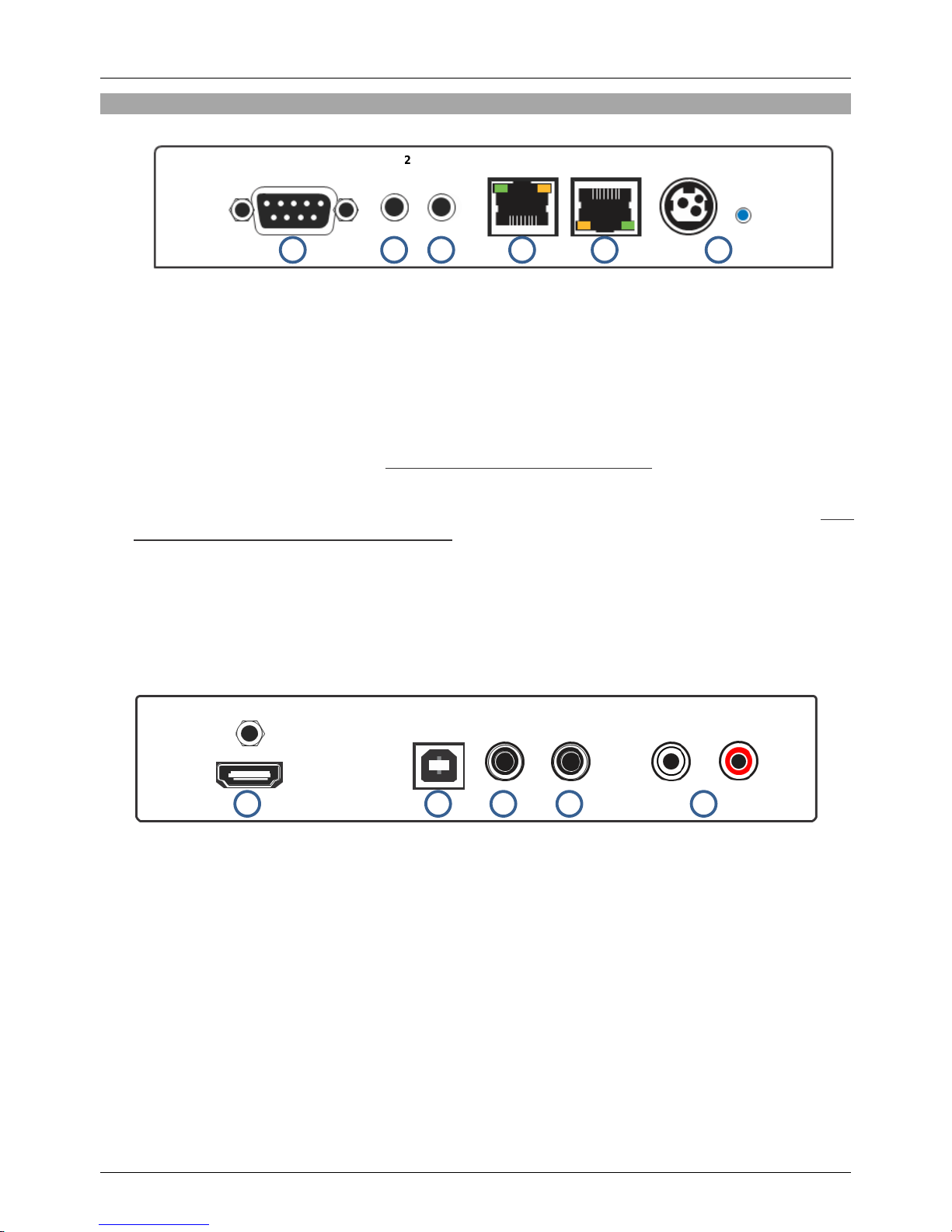
Transmitter Ports:
HDMI In, USB Typ B Buchse, Coaxial SPDIF In, Coaxial SPDIF Out, RCA x 2 In, RS232 D9
Buchse, IR In, IR Out, RJ45 Ethernet, RJ45 C6 Out (HDBaseT 2.0), 48V DC In
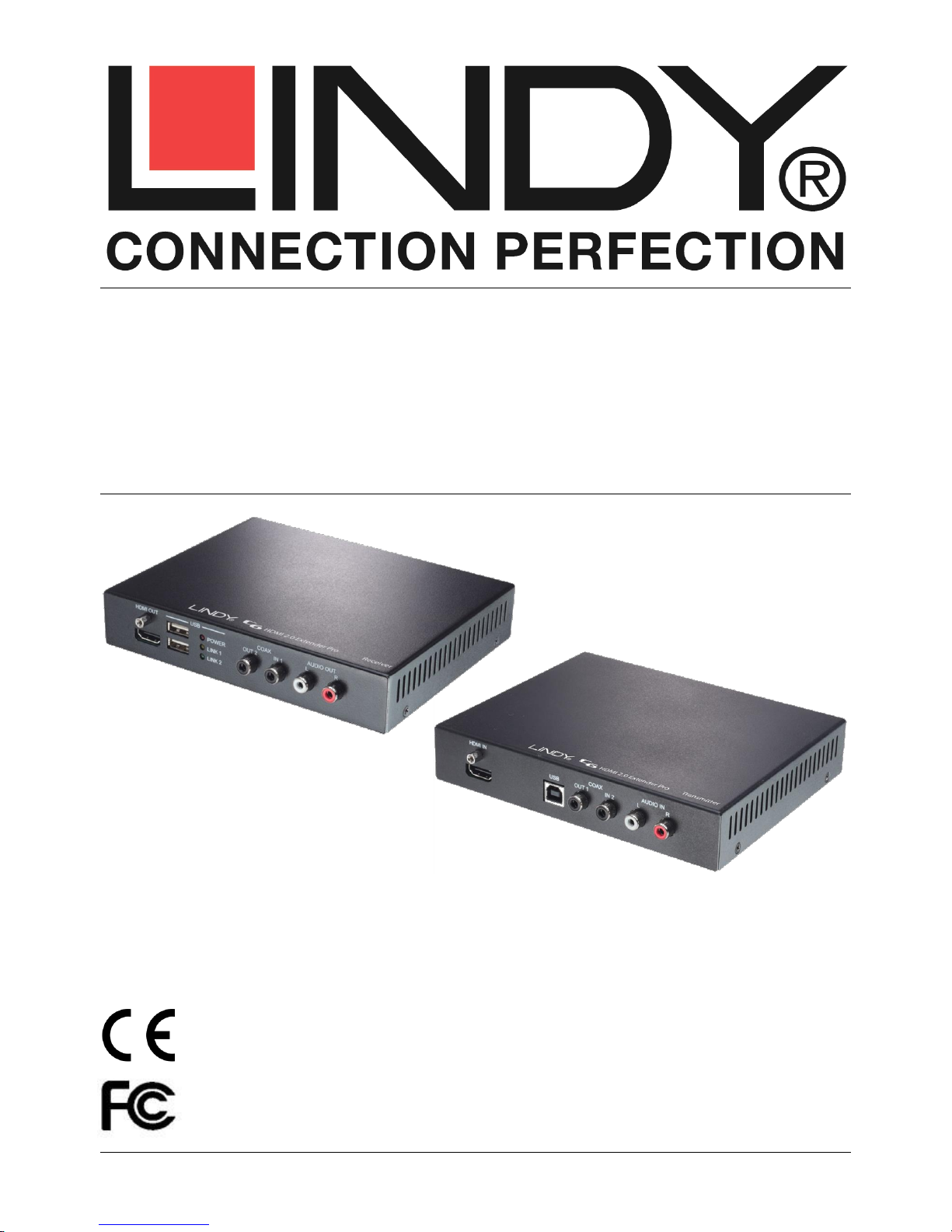
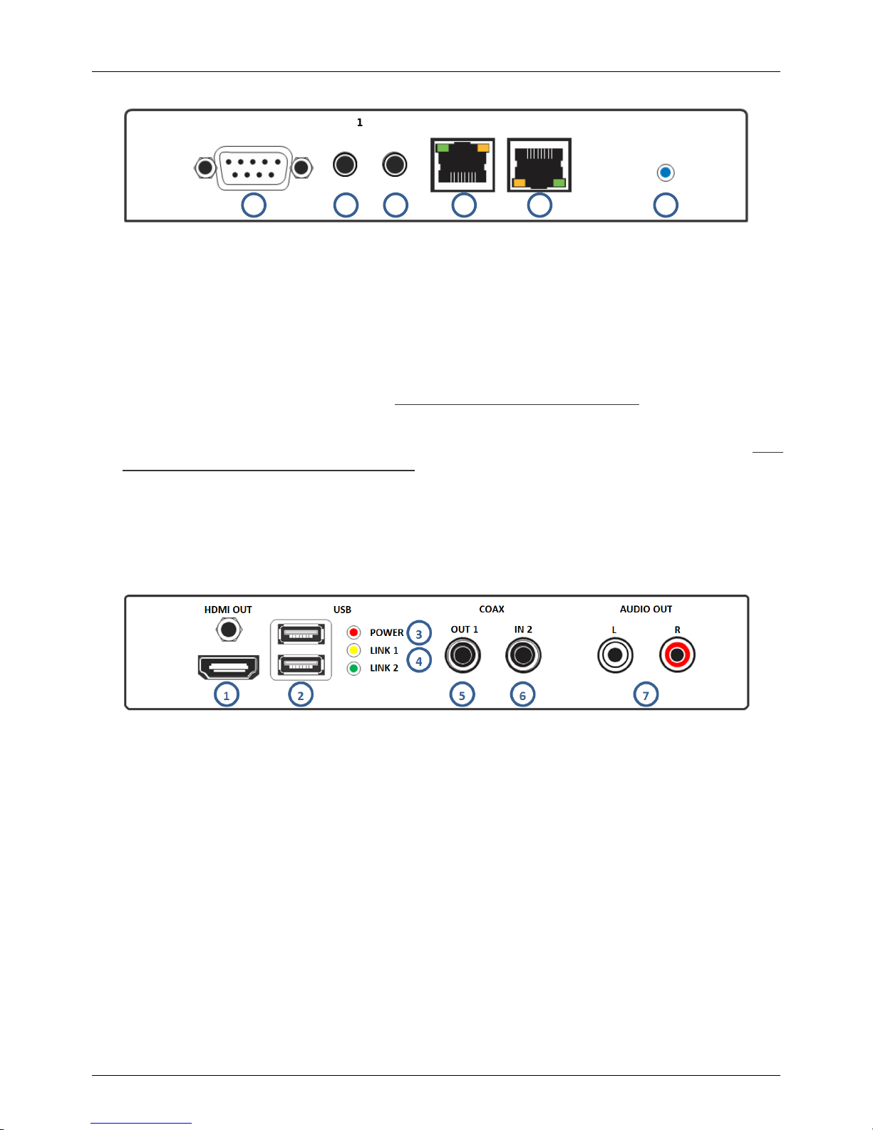
Receiver Ports:
HDMI Out, USB Typ A Buchse x 2, Coaxial SPDIF In , Coaxial SPDIF Out, RCA x 2 Out, RS232
D9 Steckerbuchse, IR In, IR Out, RJ45 Ethernet & RJ45 C6 In (HDBaseT 2.0).

Benutzerhandbuch Deutsch
Übersicht Anschlüsse
Transmitter –Vorder- und Rückseite
1. RS-232 IN
Anschluss für PC, Notebook oder RS232 Steuergerät mit D9 Kabel.
2. IR IN 2
Eingang für das mitgelieferte IR Empfängerkabel.
3. IR OUT 1
Ausgang für das mitgelieferte IR Emitterkabel.
4. LAN
Anschluss für Ethernet Netzwerk –nicht verwechseln mit HDBaseT Port!
5. CAT5e/6/7 OUT
Anschluss für das HDBaseT 2.0 CAT5e/6/7 Kabel zum CAT5e/6/7 IN Port am Receiver – nicht
verwechseln mit einem Netzwerkanschluss! Die gelbe LED leuchtet wenn eine stabile Verbindung
zum Receiver besteht. Blinken zeigt dass die Verbindung fehlerhaft ist, wenn keine elektrische
Verbindung besteht ist die gelbe LED aus. Die grüne LED leuchtet wenn das HDMI Signal HDCP
verschlüsselt ist.
6. DC 48V & Power LED
Bei bestehender 48VDC Stromversorgung leuchtet die Power LED.
1. HDMI IN
Anschluss für die HDMI Signalquelle
2. USB
USB Anschluss für PC oder anderen USB Host Controller
3. COAX OUT 1
Anschluss für Digital-Audio-Wiedergabegeräte, das Signal wird vom Receiver COAX IN1
empfangen.
4. COAX IN 2
Anschluss für Digital-Audio-Signalquelle, das Signal wird zum Receiver COAX OUT2 übertragen.
5. Audio IN L/R
Anschluss für Analog-Audio-Signalquelle, das Signal wird zum Receiver AUDIO OUT L/R
übertragen.
HDMI IN
USB
COAX
OUT 1 IN 2
AUDIO IN
L R
1
2
3
4
5
RS 232 IN
IR IN 2
IR OUT 1
LAN
CAT5e/6/7 OUT
DC 48V
POWER
1
2
3
4
5
6

Benutzerhandbuch Deutsch
Receiver –Vorder- und Rückseite
1. RS-232 OUT
RS232 Anschluss für zu steuerndes Gerät, mit D9 Kabel.
2. IR IN 1
Eingang für das mitgelieferte IR Empfängerkabel.
3. IR OUT 2
Ausgang für das mitgelieferte IR Emitterkabel.
4. LAN
Anschluss für Ethernet Netzwerkgeräte –nicht verwechseln mit HDBaseT Port!
5. CAT5e/6/7 IN
Anschluss für das HDBaseT 2.0 CAT5e/6/7 Kabel zum CAT5e/6/7 OUT Port am Receiver – nicht
verwechseln mit einem Netzwerkanschluss! Die gelbe LED leuchtet wenn eine stabile Verbindung
zum Receiver besteht. Blinken zeigt dass die Verbindung fehlerhaft ist, wenn keine elektrische
Verbindung besteht ist die gelbe LED aus. Die grüne LED leuchtet wenn das HDMI Signal HDCP
verschlüsselt ist.
6. Power LED
Bei bestehender Stromversorgung über HDBaseT durch den Transmitter leuchtet die Power LED.
1. HDMI OUT
Anschluss für die HDMI Anzeigegeräte
2. USB
USB Anschluss für Peripheriegeräte und Devices, das Signal wird vom Transmitter ausgegeben.
3. POWER LED
Bei bestehender USB-Stromversorgung leuchtet die Power LED.
4. LINK 1 & 2
Bei angeschlossenem und aktivem USB-Device leuchtet die Link LED.
5. COAX OUT 1
Anschluss für Digital-Audio-Wiedergabegeräte, das Signal wird vom Transmitter COAX IN1
empfangen.
6. COAX IN 2
Anschluss für Digital-Audio-Signalquelle, das Signal wird zum Transmitter COAX OUT2 übertragen.
7. Audio OUT L/R
Anschluss für Analog-Audio-Wiedergabegeräte / Lautsprecher, das Signal wird vom Transmitter
AUDIO IN L/R empfangen.
1
2
3
4
5
6
RS 232 OUT
IR IN 1
IR OUT 2
LAN
CAT5e/6/7 IN
POWER

Benutzerhandbuch Deutsch
Installation
WICHTIG: Bitte schalten Sie alle angeschlossenen Geräte vor der Installation aus.
Verwenden Sie hochwertige Kabel mit einer Maximallänge von 2m um Kompatibilitätsprobleme zu
vermeiden. HDMI 2.0 4K 60Hz Geräte sind sehr selektiv was die verwendeten HDMI Kabel betrifft, die
Kompatibilität in jedem speziellen Fall sollte im Vorfeld geprüft werden!
1. Schließen Sie die HDMI Signalquelle an den Transmitter an.
2. Schließen Sie das HDBaseT Cat.5e/6/7 Kabel (max. 100m) an die Cat.5e/6/7 Ports am TX und RX
an – verwenden Sie hier keine aktiven Netzwerkkomponenten und verwechseln Sie die Anschlüsse
nicht! Verwenden Sie bei großen Längen hochwertiges Installationskabel (starre Adern). Cat.5e
Kabel kann die Maximallängen nicht erreichen.
3. Schließen Sie das HDMI Darstellungsgerät (Monitor, TV, Projektor) an den Receiver an.
4. Schließen Sie das Netzteil am Transmitter (TX) an, der RX wird über das HDBaseT Kabel mit Strom
versorgt.
5. Schalten Sie die HDMI Signalquelle und das HDMI Ausgabegerät ein.
Stellen Sie die weiteren optionalen Verbindungen her.
10/100 Ethernet
TX und RX verfügen über einen Fast Ethernet Port um Devices oder Switches anzuschließen.
RS232
TX und RX können RS232 Signale übertragen um angeschlossene Geräte zu steuern. Unterstützt
werden 110 - 115.2Kbps Verbindungen.
Infrarot Fernbedienungsunterstützung
TX und RX können über die IR Ein- und Ausgänge und die mitgelieferten Emitter und Empfängerkabel
jeweils IR Signale entgegennehmen, übertragen und ausgeben. Achten Sie auf korrekte Positionierung
der IR Emitter und Empfänger.
USB
USB Signale werden zwischen den Devices an den USB Buchsen am Receiver und dem USB Typ B
Anschluss am Transmitter übertragen. Unterstützt werden Mäuse, Tastaturen, Drucker, Speichermedien,
aber keine isochronen Echtzeit USB Devices wie Kameras und Audioequipment.
Digital Audio
TX und RX übertragen Digital Audio SPDIF Coax Signale in beiden Richtungen. Es findet keine
Konvertierung mit anderen Ports statt.
Analog Audio
Analog Audio wird vom TX zum RX übertragen. Es findet keine Konvertierung mit anderen Ports statt.

Benutzerhandbuch Deutsch
Problemlösung
Es wird kein Bild angezeigt.
Prüfen Sie ob die POWER LEDs sowohl am TX wie auch am RX korrekt leuchten und ob das
Netzteil korrekt am TX angeschlossen ist.
Prüfen Sie dass das HDBaseT Kabel korrekt eingesteckt ist und die LINK Status LEDs korrekt gelb
dauerhaft leuchten. Falls dies nicht der Fall ist überprüfen Sie sowohl das Kabel wie auch die
Installation mit einem anderen kurzen RJ45-Kabel.
Schalten Sie erneut alle Geräte aus und beginnend mit TX und RX, dann die HDMI Anzeigeräte und
schließlich die HDMI Signalquelle wieder ein.
Bei manchen HDMI Geräten hilft es, das HDMI Kabel für einige Sekunden abzuziehen und wieder
anzuschließen um den HDMI Handshake zu erneuern.
Stand Mai 2015: Wie verschiedene Tests ergeben haben sind erste HDMI 2.0 Geräte sehr
wählerisch bei HDMI Kabeln. HDMI Kabel die am LG Gerät funktionieren, müssen nicht auch am
Panasonic oder Samsung Gerät funktionieren, und umgekehrt, und über Kreuz. Samsung Geräte
scheinen am selektivsten zu sein. Testen Sie bei solchen Problemen mit noch kürzeren 1m HDMI
Kabeln und ggf. auch verschiedene Kabelmodelle.
Falls Sie das Problem nicht lösen können wenden Sie sich vertrauensvoll an den Technik-Support bei
LINDY. Sie finden die weltweiten Kontaktadressen auf www.lindy.com.

Manuel Utilisateur Français
Introduction
Merci d’avoir choisi le LINDY C6 HDMI 2.0 Extender Pro. Mettant en œuvre la technologie HDBaseT 2.0
cet extender permet de transmettre les signaux HDMI (jusqu’à 4K 60Hz), USB, Ethernet, RS-232, audio
numérique et analogique et IR jusqu’à 100m, en utilisant un seul câble Cat.6/Cat.7 RJ45 de haute
qualité. Pour plus de commodité et pour permettre une installation discrète de l’unité de réception,
l’extender prend en charge la fonction PoH (Power over HDBaseT) permettant l’utilisation d’une seule
alimentation sur l’émetteur, qui alimentera les deux appareils. Pour de meilleur résultat et surtout pour
les longues distances de déport, nous recommandons l’utilisation de câble à structure monobrin.
Contenu de la livraison
38200
C6 Extender Pro
Alimentation 48V
Câble secteur C13
Câble d’extension IR x 2
Ce manuel
38201
C6 Extender Pro (RX)
Câble d’extension IR x 1
Ce manuel
38202
C6 Extender Pro (TX)
Alimentation 48V
Câble secteur C13
Câble d’extension IR x 1
Ce manuel
Caractéristiques
Etend les signaux HDMI 2.0 non compressés jusqu’à 100m en utilisant la technologie HDBaseT 2.0
Utilise un seul câble pour étendre les signaux HDMI, USB, RS-232, IR, Ethernet et audio
Fonctionnalité Power over HDBaseT intégrée signifiant que l’extender ne requiert qu’une seule
alimentation
Extension bidirectionnelle des signaux IR, Ethernet et audio numérique
Conçu pour une utilisation avec des systèmes 3D/HDTV Home Cinéma, installations
professionnelles HDTV, systèmes d’ordinateurs, installation multimédia et de centres de contrôle.
Spécifications
Prise en charge de la technologie HDBaseT 2.0 jusqu’à 100m avec du câble CAT6/7 ou 90m avec
du câble CAT5e
Compatible HDMI 2.0 et pleine conformité HDMI 1.4
Résolutions HDMI 2.0: 4096/3840x2160p60, 1080p120
Résolutions HDMI 1.4: 3840x2160p30, 1080p24/30/50/60, 1080i, 720p, 576p, 480p
Prise en charge des profondeurs de couleur:
30/36/48 bit (4:4:4) @ 1080p60
24 bit (4:4:4) @ 3840x2160p30
24 bit (4:2:0) @ 4096/3840x2160p60
Prise en charge pour les signaux 3D, 1080p 3D inclus
Conforme HDCP 1.4, pas de prise en charge HDCP 2.2
Formats audio: LPCM, DTS Digital, DTS HD, Dolby Digital & Dolby True HD
IR bidirectionnelle avec prise en charge des fréquences 30-50kHz
Extension bidirectionnelle externe de l’audio numérique (Coaxial SPDIF)
Extension additionnelle externe de l’audio stéréo analogique (RCA x 2)
Prise en charge USB 2.0, 10/100 Ethernet & RS-232 (110-115.2Kbit/s)
Longueur maximale de câbles HDMI, 5m en entrée comme en sortie
Ports sur le Transmitter/émetteur:
HDMI femelle In, USB de type B femelle, Coaxial SPDIF In , Coaxial SPDIF Out, RCA x 2 In,
RS-232 Sub-D 9 femelle, IR In, IR Out, RJ45 Ethernet, RJ45 C6 Out & 48V DC In
Ports sur le Receiver/récepteur:
HDMI femelle Out, USB de type A femelle x 2, Coaxial SPDIF In , Coaxial SPDIF Out, RCA x 2
Out, RS-232 Sub-D 9 mâle, IR In, IR Out, RJ45 Ethernet & RJ45 C6 In.

Manuel Utilisateur Français
Vue d’ensemble
Transmitter/émetteur –Panneaux avant et arrière
1. RS-232 IN
Se connecte à un PC ou Laptop avec un câble Sub-D 9 pour la transmission des commandes RS-
232.
2. IR IN 2
Connectez ici le câble d’extension IR pour la réception des signaux IR. Assurez-vous que la
télécommande utilisée est en ligne directe avec le récepteur IR.
3. IR OUT 1
Connectez ici l’émetteur IR pour l’émission des signaux IR. Placez l’émetteur IR en ligne directe de
l’équipement à contrôler.
4. LAN
A connecter à une connexion internet ou réseau –NE JAMAIS connecter à un port HDBaseT.
5. CAT5e/6/7 OUT
A connecter au port CAT5e/6/7 IN de l’unité Receiver/récepteur avec une liaison par câble single
CAT5e/6/7 dédiée pour la transmission de tous les signaux de données – NE JAMAIS connecter à un
port réseau. La LED jaune s’allume pour représenter une liaison stable avec le récepteur, si elle
clignote irrégulièrement cela indique une erreur de liaison ou si elle ne s’allume cela voudra dire
qu’aucune liaison n’est établie avec le récepteur. La LED verte s’allume pour représenter un signal
HDMI contenant des signaux HDCP.
6.DC 48V & Power LED
Branchez l’alimentation 48V DC sur l’unité et connectez ensuite l’adaptateur à une prise secteur, la
LED Power s’allumera.
1. HDMI IN
A connecter à l’équipement source HDMI, comme un PC ou un lecteur Blu-ray.
2. USB
A connecter à un PC ou Laptop pour la transmission des données ou pour contrôler les ports USB du
récepteur.
3. COAX OUT 1
A connecter aux haut-parleurs avec une entrée coaxiale pour recevoir l’audio de COAX IN 1 du
récepteur.
HDMI IN
USB
COAX
OUT 1 IN 2
AUDIO IN
L R
1
2
3
4
5
RS 232 IN
IR IN 2
IR OUT 1
LAN
CAT5e/6/7 OUT
DC 48V
POWER
1
2
3
4
5
6

Manuel Utilisateur Français
4. COAX IN 2
A connecter à une source audio tel qu’un amplificateur audio/vidéo, l’audio est transmis au port COAX
OUT2 du récepteur.
5. Audio IN L/R
A connecter à une source audio comme un lecteur CD, l’audio est transmis au port AUDIO OUT L/R
du récepteur.
Receiver/récepteur –panneaux avant et arrière
1. RS-232 OUT
A connecter à un appareil qui est contrôlé par des commandes RS-232 en utilisant un câble Sub-D
9.
2. IR IN 1
Connectez ici le câble d’extension IR pour la réception des signaux IR. Assurez-vous que la
télécommande utilisée est en ligne directe de l’extender IR.
3. IR OUT 2
Connectez ici le câble émetteur IR pour la transmission des signaux IR. Placez l’émetteur IR en
ligne directe de l’équipement à contrôler.
4. LAN
A relier à une connexion internet ou réseau –NE JAMAIS connecter à un port HDBaseT.
5. CAT5e/6/7 IN
A connecter au port CAT5e/6/7 OUT de l’unité Transmitter/ émetteur avec une liaison par câble
single CAT5e/6/7 dédiée pour la transmission de tous les signaux de données – NE JAMAIS
connecter à un port réseau. La LED jaune s’allume pour représenter une liaison stable avec
l’émetteur, si elle clignote irrégulièrement cela indique une erreur de liaison ou si elle ne s’allume
cela voudra dire qu’aucune liaison n’est établie avec l’émetteur. La LED verte s’allume pour
représenter un signal HDMI contenant des signaux HDCP.
6. Power LED
La LED s’allume lorsque l’alimentation est reçue via PoE du Transmitter/émetteur
1. HDMI OUT
A connecter à un équipement d’affichage HDMI comme une TV ou un projecteur.
2. USB
A connecter à un périphérique USB à utiliser avec le PC/Laptop connecté à l’émetteur.
3. POWER LED
S’allume pour indiquer que l’alimentation est disponible via USB.
1
2
3
4
5
6
RS 232 OUT
IR IN 1
IR OUT 2
LAN
CAT5e/6/7 IN
POWER

Manuel Utilisateur Français
4. LINK 1 & 2
S’allume pour indiquer qu’un périphérique USB est connecté avec un signal actif.
5. COAX OUT 1
Connectez ici les haut-parleurs avec entrée coaxial pour recevoir l’audio du port COAX IN 1 du
récepteur.
6. COAX IN 2
A connecter à une source audio comme un amplificateur audio/vidéo, l’audio est transmis au port
COAX OUT2 du récepteur
7. Audio OUT L/R
Connectez ici les haut-parleurs avec entrée RCA, l’audio est reçu des ports AUDIO IN L/R de
l’émetteur.
Installation
Important! Avant de débuter l’installation, assurez-vous que tous les appareils soient hors tension.
Les étapes suivantes se réfèrent à une installation de base, avec un équipement HDMI, si vous utilisez
des appareils DVI, veuillez substituer les câbles HDMI par des câbles DVI vers HDMI comme requis.
1. Connectez votre source HDMI à l’émetteur de l’extender HDMI en utilisant un câble HDMI (longueur
maximum 5m).
2. Connectez une extrémité du câble Cat.5e (longueur max. 90m) ou Cat.6/7 (longueur max. 100m) au
port CAT.5e/6/7 Out (HDBaseT) du Transmitter/émetteur et l’autre extrémité au port CAT.5e/6/7 In
(HDBaseT) du Receiver/récepteur. L’utilisation de câble monobrin est recommandée.
3. Utilisez un autre câble HDMI (longueur maximum 5m) pour connecter votre affichage HDMI au port
HDMI de sortie (output) de l’unité Receiver/récepteur.
4. Branchez l’alimentation DC au Transmitter/émetteur et mettez sous tension.
5. Mettez votre source et votre affichage HDMI sous tension pour compléter l’installation.
En plus des étapes d’installation de base ci-dessus, le C6 HDMI 2.0 Extender Pro peut également
fournir les fonctionnalités additionnelle/optionnelles suivantes:
Ethernet 10/100
Les unités Transmitter/émetteur et Receiver/récepteur offrent toutes les deux un port de connexion RJ45
unique pour la connexion d’équipements réseau comme un routeur, switch réseau, caméra IP, point
d’accès sans fil ou Smart TV.
Série RS-232
Le Transmitter/émetteur et Receiver/récepteur offrent tous deux une connexion Sub-D 9 série pour
l’extension de signaux de contrôle.
Contrôle infra rouge
Les unités Transmitter/émetteur et Receiver/récepteur offrent tous deux des ports IR In et Out, avec une
paire de câbles d’extension IR fournies. Les câbles d’extension permettent l’utilisation d’une
télécommande IR de l’émetteur vers le récepteur ou vice versa.
USB
Le Transmitter/émetteur dispose d’un port USB de type B femelle pour la connexion à un ordinateur via
un câble standard USB A/B (non inclus). Le Receiver/récepteur dispose de deux ports USB de type A
femelle pour la connexion de périphériques USB basiques comme un clavier, une souris, clé USB ou
imprimante –les caméras Web ne sont pas prises en charge !

Manuel Utilisateur Français
Audio numérique
Les unités Transmitter/émetteur et Receiver/récepteur offrent tous deux un port Coaxial SPDIF In et Out,
permettant aux signaux audio numériques d’être séparément transmis du Transmitter/émetteur au
Receiver/récepteur, du Receiver/récepteur au Transmitter/émetteur ou dans les deux directions
simultanément.
Audio analogique
Le Transmitter/émetteur dispose d’une entrée analogique stéréo via 2 x RCA avec la sortie
correspondante sur le Receiver/récepteur, permettant à une source audio analogique additionnelle d’être
transmise en même temps qu’un signal HDMI.
Dépannage
Aucune image ne s’affiche sur l’écran.
En mai 2015, il a été constaté qu'il existe des différences significatives dans les longueurs/types de
câble et même les ports d’entrée qui peuvent être utilisés sur les différentes marques de HDTV en
utilisant l’HDMI 2.0 4K 60Hz. Si vous rencontrez des problèmes, veuillez s’il vous plait suivre les
étapes suivantes:
Essayez un autre port d’entrée sur votre HDTV.
Réduisez la longueur des câbles en entrée et sortie à 1m.
Essayez un autre modèle de câble HDMI de 1m.
Vérifiez que les connexions d’alimentation DC utilisées par l’alimentation externe sont bien
branchées et que la LED Power est allumée sur le Transmitter/émetteur et le Receiver/récepteur.
Vérifiez que le câble Cat.5e/6/7 est bien connecté et que les LED d’état jaune des deux ports
CAT5e/6/7 In et Out sont allumés.
Mettez tous les appareils hors tension, mettez les sous tension dans l’ordre suivant: en premier,
l’unité transmitter/émetteur, puis l’affichage et finalement la source.
Pour plusieurs appareils HDMI, il peut être utile de débrancher et rebrancher leurs connexions HDMI
pour réinitialiser le handshake et l’identification HDMI.
Réduisez la longueur des câbles Cat.5e/6/7 ou HDMI utilisés, ou utilisez une qualité de câbles
supérieure.

Manuale Italiano
Introduzione
Vi ringraziamo per aver acquistato l’Extender LINDY C6 HDMI 2.0 Pro. Questo prodotto utilizza la
tecnologia HDBaseT 2.0 per trasmettere segnali HDMI (fino a 4K 60Hz), USB, Ethernet, RS-232, Audio
Digitali & Analogici e IR fino a 100m di distanza utilizzando un singolo cavo RJ45 Cat.6/Cat.7 di alta
qualità. Per rendere più agevole l’installazione dell’Extender ed in particolare il posizionamento dell’unità
ricevente questo dispositivo supporta la distribuzione dell’alimentazione (PoH: Power-over-HDBaseT) che
permette di fornire corrente all’unità remota da quella locale tramite il cavo cat.6/7. Per ottenere risultati di
elevata qualità vi consigliamo, specialmente su lunghe distanze, l’utilizzo di cavi a conduttore monofilare
(solid core).
Contenuto della confezione
38200
Extender C6 Pro (TX & RX)
Alimentatore 48V
Cavo di alimentazione C13
Cavo di estensione IR x 2
Questo manuale
38201
Extender C6 Pro (RX)
Cavo di estensione IR x 1
Questo manuale
38202
Extender C6 Pro (TX)
Alimentatore 48V
Cavo di alimentazione C13
Cavo di estensione IR x 1
Questo manuale
Caratteristiche
Estende segnali HDMI 2.0 fino a 100m di distanza utilizzando la tecnologia HDBaseT 2.0
Utilizza un singolo cavo per estendere segnali HDMI, USB, RS-232, IR, Ethernet e Audio
Funzione Power over HDBaseT integrata (permette di alimentare il Sistema con il solo alimentatore
connesso al trasmettitore)
Estensione Bi-direzionale dei segnali IR, Ethernet e Digital Audio
Progettato per l’utilizzo con HDTV/3D, Home Theatre, installazioni HDTV professionali, Computer
Systems, sistemi e centri di controllo multimediali.
Specifiche
Supporta la tecnologia HDBaseT 2.0 e raggiunge 100m di distanza utilizzando cavi CAT6/7 o 90m
utilizzando cavi CAT5e
Conforme allo standard HDMI 2.0 e compatibile con HDMI 1.4
Risoluzioni HDMI 2.0: 4096/3840x2160p60, 1080p120
Risoluzioni HDMI 1.4: 3840x2160p30, 1080p24/30/50/60, 1080i, 720p, 576p, 480p
Profondità colore supportate:
30/36/48 bit (4:4:4) @ 1080p60
24 bit (4:4:4) @ 3840x2160p30
24 bit (4:2:0) @ 4096/3840x2160p60
Supporto segnali 3D incluso 1080p 3D
Supporto HDCP 1.4, NON compatibile con lo standard HDCP 2.2
Formati Audio supportati: LPCM, DTS Digital, DTS HD, Dolby Digital & Dolby True HD
Supporto segnali IR Bidirezionali (frequenze da 30 a 50kHz)
Estensione Bidirezionale Audio digitale su canale esterno (SPDIF Coassiale)
Estensione Addizionale per segnale audio analogico stereo su canale esterno (RCA x 2)
Supporta USB 2.0, Ethernet 10/100 & RS-232 (110-115.2Kbps)
Lunghezza massima cavi HDMI: Fino a risoluzioni 4K 30Hz: 5m in ingresso e uscita / Per risoluzioni
4K 60Kz: 2m in ingresso e uscita
Porte Unità Trasmittente:
Ingresso HDMI, USB Tipo B, 2 x SPDIF Coassiale (1 ingresso e 1 uscita), 2 x Ingressi RCA, RS-
232 9 pin, IR In, IR Out, RJ45 Ethernet, Uscita RJ45 C6 Out & Ingresso 48V DC
Porte Unità Ricevente:
Uscita HDMI, 2xUSB Tipo A, 2 x SPDIF Coassiale (1 ingresso e 1 uscita), 2 x Uscite RCA, RS-232
9 pin D, IR In, IR Out, RJ45 Ethernet & Ingresso RJ45 C6

Manuale Italiano
Panoramica
Trasmettitore –Pannello Anteriore & Posteriore
1. RS-232 IN
Collegate questa porta ad un PC con interf. seriale tramite un cavo 9 pin per inviare comandi RS232
2. IR IN 2
Collegate a questa porta il cavo si estensione IR fornito per la ricezione dei comandi IR. Assicuratevi
che il telecomando abbia visibilità diretta del ricevitore IR.
3. IR OUT 1
Collegate a questa porta il cavo con l’emettitore IR fornito per la trasmissione dei comandi IR.
Assicuratevi che l’apparato da controllare abbia visibilità diretta dell’emettitore IR.
4. LAN
Collegate questa porta ad una rete Ethernet –NON CONNETTERLA MAI AD UNA PORTA
HDBASET .
5. CAT5e/6/7 OUT
Collegate questa porta alla corrispondente porta CAT5e/6/7 IN sul Ricevitore con un singolo cavo
CAT5e/6/7 dedicato per la trasmissione di tutti i segnali. – NON CONNETTERLA MAI AD UNA
PORTA DI RETE ETHERNET. Il LED giallo ci accende per indicare una connessione stabile con il
ricevitore. Se lampeggia irregolarmente indica un errore sulla connessione mentre se rimane spento
indica assenza di connessione. Quando il LED Verde è acceso indica che nel segnale HDMI è
presente una codifica HDCP.
6. DC 48V & Power LED
Collegate a questa porta l’alimentatore a 48V DC dopo averlo collegato ad una presa di corrente (il
LED si illuminerà)
1. HDMI IN
Collegate a questa porta la sorgente HDMI (es. PC o lettore Blu-ray)
2. USB
Collegate qui una porta USB del PC per controllare le porte USB sul ricevitore
3. COAX OUT 1
Collegate questa porta ad un sistema di casse con ingresso coassiale per ricevere audio dalla porta
COAX IN 1 posta sul ricevitore.
HDMI IN
USB
COAX
OUT 1 IN 2
AUDIO IN
L R
1
2
3
4
5
RS 232 IN
IR IN 2
IR OUT 1
LAN
CAT5e/6/7 OUT
DC 48V
POWER
1
2
3
4
5
6

Manuale Italiano
4. COAX IN 2
Collegate una sorgente audio come un amplificatore AV, per inviare il segnale audio digitale alla porta
COAX OUT2 del ricevitore.
5. Audio IN L/R
Collegate una sorgente audio come un CD player per inviare il segnale alle porte AUDIO OUT L/R del
ricevitore
Ricevitore –Pannello Anteriore & Posteriore
1. RS-232 OUT
Collegate con un cavo 9 pin a questa porta un dispositivo da controllare via interfaccia RS-232.
2. IR IN 1
Collegate a questa porta il cavo si estensione IR fornito per la ricezione dei comandi IR. Assicuratevi
che il telecomando abbia visibilità diretta del ricevitore IR.
3. IR OUT 2
Collegate a questa porta il cavo con l’emettitore IR fornito per la trasmissione dei comandi IR.
Assicuratevi che l’apparato da controllare abbia visibilità diretta dell’emettitore IR.
4. LAN
Collegate questa porta ad una rete Ethernet –NON CONNETTERLA MAI AD UNA PORTA
HDBASET .
5. CAT5e/6/7 IN
Collegate questa porta alla corrispondente porta CAT5e/6/7 IN sul Trasmettitore con un singolo cavo
CAT5e/6/7 dedicato per la trasmissione di tutti i segnali. – NON CONNETTERLA MAI AD UNA PORTA
DI RETE ETHERNET. Il LED giallo ci accende per indicare una connessione stabile con il ricevitore. Se
lampeggia irregolarmente indica un errore sulla connessione mentre se rimane spento indica assenza
di connessione. Quando il LED Verde è acceso indica che nel segnale HDMI è presente una codifica
HDCP.
6. Power LED
Il LED si illumina quando l’unità riceve alimentazione dal trasmettitore.
1
2
3
4
5
6
RS 232 OUT
IR IN 1
IR OUT 2
LAN
CAT5e/6/7 IN
POWER
This manual suits for next models
2
Table of contents
Languages:
Other Lindy Extender manuals

Lindy
Lindy HDMI 4K Premium C6 User manual

Lindy
Lindy 38205 User manual

Lindy
Lindy 42708 User manual

Lindy
Lindy 37578 User manual

Lindy
Lindy 32338 User manual

Lindy
Lindy 42791 User manual

Lindy
Lindy 32681 User manual

Lindy
Lindy 70466 User manual

Lindy
Lindy Video Extenders VE-120 User manual

Lindy
Lindy 39378 User manual
Popular Extender manuals by other brands

Intelix
Intelix DIGI-USB2-4P installation guide

ATEN
ATEN VE883 user manual

Guntermann & Drunck
Guntermann & Drunck DVI-Vision-Fiber-AR Installation and operation

Network Technologies
Network Technologies XTENDEX ST-C6USBH-300 operating manual

Westermo
Westermo DDW-120 user guide

Tekvox
Tekvox TPUH460S user manual