Sinee EM760 Series User manual

EM760 Series High Performance Vector Drive User Guide
1
Foreword
Thank you for choosing Sine Electric EM760 series high performance vector inverter.
Data number: 31010200
Release time: 2021-7
Version: 102
EM 760 series inverter is a high-performance vector control inverter launched by Shenzhen
Sine Electric Co.,Ltd, which realizes the integration of synchronous motor drive and asynchronous
motor drive : supports three-phase AC asynchronous motor and permanent magnet synchronous motor;
supports a variety of international leading drive control technologies ——Improved vector VF
control technology ( VVF ), speed sensorless vector control technology (SVC) and speed sensor
vector control technology (FVC); support two output forms of speed and torque; support Wi - Fi
access Function and background software debugging function ; support expansion - I/O expansion
card, communication bus expansion card and various PG cards .
EM 760 series high performance vector inverter has the following characteristics :
⚫Built-in DC reactor from 18.5 kW to reduce input current distortion, improve power factor
and enhance product reliability;
⚫High torque control accuracy: SVC/±5 % rated torque, FVC/±3 % rated torque;
⚫Wide speed regulation range and high control precision : SVC/1:200 (±0.2% ) , FVC/1:1000
(±0.02 % ) rated speed;
⚫Low frequency carrier: VVF/ 3 Hz/150%, SVC/0.25Hz/150%, FVC/0Hz/180 % ;
⚫Overvoltage stall, fast current limiting, overload, overheating, unloading, overspeed and
other multiple guarantees;
⚫Support I/O expansion: 3 digital inputs, 2 relay outputs, 1 -10V~10V voltage input, 1 sensor
input;
⚫Support communication bus expansion, realize various industrial network interconnection:
485 bus, PROFINET network, CANopen network and EtherCAT network;
⚫Support a variety of encoders: ABZ incremental, UVW incremental, UVW wire saving, resolver
and sine cosine ;
⚫Support mobile phone APP debugging or monitor inverter status;
⚫Support Wi-Fi module or serial port access;
⚫Rich and convenient PC tool software functions.
Before using EM 760 series high performance vector inverter, please read this guide

EM760 Series High Performance Vector Drive User Guide
2
carefully and keep it properly.
When the inverter is connected to the motor for the first time, please correctly select
the motor type (asynchronous motor or synchronous motor), and set the motor nameplate parameters:
rated power, rated voltage, rated current, rated frequency, rated speed, motor connection and
rated power factor etc. If it is the FVC drive control mode, it is necessary to select the PG
card and set the encoder parameters correctly.
As we always strive to improve our products and product information, the information provided
by the company is subject to change without notice.
For the latest changes and more, please visit www.sinee.cn
EM760 Series High Performance Vector Drive User Guide
3
Safety Precautions
Safety Definition: In this manual, safety precautions are divided into the following two
categories;
DANGER : A situation that could result in serious injury or even death due to a hazard
caused by failure to follow instructions.
CAUTION : Moderate or minor injury and equipment damage may result due to hazards caused
by failure to follow instructions.
When installing, debugging and maintaining the system, please read this chapter carefully,
and be sure to operate in accordance with the safety precautions required in this chapter. Any
damage or loss caused by illegal operations has nothing to do with our company.
Safety Precautions
Before installation:
Danger
1、Please do not install it when you find water in the package, missing parts or damaged parts
when unpacking!
2、Please do not install if the outer packaging logo does not match the actual name!
Notice
1、When unpacking the wooden box, please wear gloves and do not touch the sealing iron on the
wooden box with your hands, otherwise there is a danger of injury!
2、When carrying the inverter, be sure to hold the bottom of the inverter. If you carry it by
the front cover, the main body of the inverter may fall, and there is a danger of being smashed!
3、It should be handled with care, otherwise there is a risk of damage to the equipment!
4、Please do not use the damaged inverter or the inverter with missing parts, there is a danger
of injury!
5、Do not touch the components of the control system with your hands, otherwise there is a danger
of static electricity damage to the inverter!
6、The frequency converter has been subjected to the withstand voltage test before leaving the
factory. Please do not perform the withstand voltage test on the frequency converter,
otherwise there is a risk of damage to the frequency converter!
When installing:
Danger
1、Please install it on flame-retardant objects such as metal, and keep away from combustibles,
otherwise it may cause a fire!
2、Do not unscrew the fixing bolts of the device components, especially the bolts marked in red!
Notice
1、Do not install the inverter in a place where there is conductive dust, corrosive gas, salt
mist, oil, condensation, vibration or direct sunlight!
2、Do not let the wire ends or screws fall into the inverter, otherwise the inverter will be
damaged!
3、When the inverter is placed in a relatively closed cabinet or space, please pay attention
to the installation gap to ensure the heat dissipation effect.
EM760 Series High Performance Vector Drive User Guide
4
When wiring:
Danger
1、The instructions in this manual must be followed, and the construction must be carried out
by professional electrical engineers, otherwise there will be a danger of electric shock!
2、There must be a circuit breaker between the inverter and the power supply (recommended to
use a specification greater than or equal to and closest to 2 times the rated current),
otherwise a fire may occur!
3、Before wiring, please confirm that the power supply is disconnected (zero energy), and do
not perform wiring work with electricity, otherwise there is a danger of electric shock! !
4、Never connect input power to the output terminals (U, V, W) of the inverter. Pay attention
to the markings of the terminals, and do not connect the wrong wires! Otherwise, the inverter
will be damaged or even fire!
5、Please ground the inverter correctly and reliably according to the standard, otherwise there
will be danger of electric shock!
Notice
1、Please connect the inverter output terminals U, V, W to the motor input terminals U, V, W
respectively. Inconsistent phase sequence can cause the motor to reverse.
2、Make sure that the wiring is in compliance with EMC requirements and the safety standards
of the area. Please refer to the preferred recommendations for the wire size used. Otherwise
an accident may occur!
3、Never connect the braking resistor directly between the DC bus and terminals, otherwise
it will cause damage to the inverter and cause fire!
4、Please fasten the main circuit terminals with a screwdriver with specified torque, otherwise
there is a risk of fire.
5、Do not connect phase-shift capacitors and LC/RC noise filters to the output circuit.
6、Do not connect the electromagnetic switch and electromagnetic contactor to the output circuit,
otherwise the overcurrent protection circuit of the inverter will act, and in severe cases,
it will cause internal damage to the inverter.
7、Do not disassemble the connecting cables inside the inverter, otherwise the inverter may be
damaged.
Before power on:
Danger
1、Please confirm whether the voltage level of the input power supply is consistent with the
rated voltage level of the inverter, otherwise it will cause equipment damage or fire;
2、Confirm whether the wiring positions on the power input terminals (R, S, T) and output
terminals (U, V, W ) are correct;
3、Pay attention to check whether there is a short circuit in the peripheral circuit connected
to the inverter, and whether the connected circuit is fastened, otherwise the inverter will
be damaged!
Notice
1、The inverter must cover the cover before powering on, otherwise it may cause electric shock!
2、The wiring of all peripheral accessories must comply with the instructions of this manual,
and the correct wiring is provided according to the circuit connection method provided in
this manual. Otherwise it may cause an accident!
After power up:
Danger
1、Do not touch the inverter and surrounding circuits, otherwise there is a danger of electric
EM760 Series High Performance Vector Drive User Guide
5
shock!
2、If the indicator light does not light up and the keyboard does not display after power-on,
please turn off the power switch immediately. After 10 minutes of power-off, check whether
the wiring is wrong. Do not touch the R, S, T and any power terminals of the inverter with
hands or screwdrivers, otherwise there is a danger of electric shock. After eliminating the
cause of the wiring error, you should contact our customer service staff immediately.
3、After power-on, never touch any terminal of the inverter, never touch the motor, otherwise
there is a danger of electric shock!
4、Do not disassemble any parts of the inverter when the inverter is powered on.
Notice
1、If parameter identification is required, please pay attention to the danger of injuring people
during the rotation of the motor. Please confirm the safety before proceeding, otherwise it
may cause an accident!
2、Do not arbitrarily change the parameters of the inverter manufacturer, otherwise it may cause
damage to the equipment!
During maintenance:
Danger
1、Do not repair and maintain the equipment with electricity, otherwise there is a danger of
electric shock!
2、Cut off the main circuit power supply and confirm that the keyboard display interface is off
for at least 10 minutes before maintenance and repair of the inverter, otherwise the residual
charge on the capacitor will cause harm to people!
3、Personnel without professional training should not repair and maintain the inverter,
otherwise it will cause personal injury or equipment damage!
4、After replacing the inverter, parameter setting and inspection must be carried out, and all
pluggable interfaces must be plugged and unplugged in the case of power failure!
5、When the synchronous machine rotates, it will generate electricity. In the case of power
failure, it is necessary to wait for the motor to stop for 10 minutes, disconnect the connection
between the motor and the inverter, and take safety measures before maintenance and repair
of the inverter. Otherwise, there is a danger of electric shock. !
Running:
Danger
1、Do not touch the cooling fan, radiator and discharge resistor to test the temperature,
otherwise it may cause burns!
2、Non-professional technicians should not detect signals during operation, otherwise it may
cause personal injury or equipment damage!
Notice
1、During the operation of the inverter, it should be avoided that something falls into the
equipment, otherwise the equipment will be damaged!
2、Do not use the method of contactor on and off to control the start and stop of the inverter,
otherwise it will cause equipment damage!
Precautions
Motor insulation inspection
Before using the motor for the first time, before using it for a long time, and during regular
inspection, the motor insulation should be checked to prevent damage to the inverter due to the
insulation failure of the motor winding. During insulation inspection, the motor wiring must be

EM760 Series High Performance Vector Drive User Guide
6
separated from the inverter. It is recommended to use a 500V voltage megohmmeter, and it should
be ensured that the measured insulation resistance is not less than 5MΩ.
Thermal protection of the motor
If the selected motor does not match the rated capacity of the inverter, especially when the rated
power of the inverter is greater than the rated power of the motor, be sure to adjust the motor
protection related parameter values in the inverter or install a thermal relay in front of the
motor to protect the motor.
Operation above power frequency
Some inverters can provide output frequencies of 0.00Hz to 600.00Hz/0.0Hz to 3000.0Hz. If the
customer needs to run the motor above the rated frequency, please consider the bearing capacity
of the mechanical device. Otherwise, there will be equipment damage and even life-threatening
accidents.
When there is a varistor on the output side or a capacitor to improve power factor
The output of the inverter is PWM wave. If the output side is installed with a capacitor for
improving power factor or a varistor for lightning protection, it is easy to cause instantaneous
overcurrent of the inverter or even damage the inverter. Please do not use it.
Use other than rated voltage
It is not suitable to use the inverter outside the allowable working voltage range specified in
the manual, otherwise it will easily cause damage to the components in the inverter. If necessary,
please use the corresponding step-up or step-down device for voltage transformation.
Lightning strike protection
This series of inverters is equipped with surge current protection device, which has a certain
self-protection ability for inductive lightning. Customers should also install lightning
protection device at the front end of the inverter for frequent lightning occurrences.
Altitude and Derating Usage
In areas with an altitude of more than 1000m, the cooling effect of the inverter is deteriorated
due to the thin air, and it is necessary to derate the use (every 100m of height, derate by 1%,
and the maximum altitude is 3000m; when it exceeds 50 °C, it is necessary to press The temperature
is derated by 1.5% for every 1°C increase in temperature, and the maximum operating temperature
is 60 °C). In this case, please contact our company for technical consultation.
Pay attention to the scrapping of the inverter
The electrolytic capacitors of the main circuit and the electrolytic capacitors on the printed
board may explode when they are burned. Toxic gas will be generated when the plastic parts are
burned. Please dispose of them as industrial waste.
Scope of use of this product
This product is not designed and manufactured for use in devices or systems where life is at stake
and should not be used in these situations.
This product is produced under strict quality control, but please configure safety devices when
it is used in equipment that may cause serious accidents or losses due to the failure of this
product.
Electric shock
Please read the requirements in this safety precaution carefully! Cut off the main circuit power
supply and confirm that the keyboard display interface is off for at least 10 minutes before

EM760 Series High Performance Vector Drive User Guide
7
maintenance and repair of the inverter, otherwise the residual charge on the capacitor will cause
harm to people!

EM760 Series High Performance Vector Drive User Guide
8
TABLE OF CONTENTS
PREFACE ..............................................................................................................................1
SAFETY PRECAUTIONS .........................................................................................................3
SAFETY ..............................................................................................................................3
NOTE ..................................................................................................................................5
CHAPTER 1 _ SUMMARY .............................................................................................9
CHAPTER 2 _ INSTALL ...............................................................................................12
CHAPTER 3 _ WIRING ................................................................................................18
CHAPTER 4 _ KEYBOARD OPERATION .................................................................28
CHAPTER 5 _ TEST RUN .............................................................................................32
CHAPTER 6 _ TROUBLESHOOTING .......................................................................36
CHAPTER 7 _ CARE AND MAINTENANCE ............................................................42
CHAPTER 8 _ OPTION .................................................................................................44
CHAPTER 9 _ FUNCTION CODE TABLE .................................................................47

EM760 Series High Performance Vector Drive User Guide
9
Summary
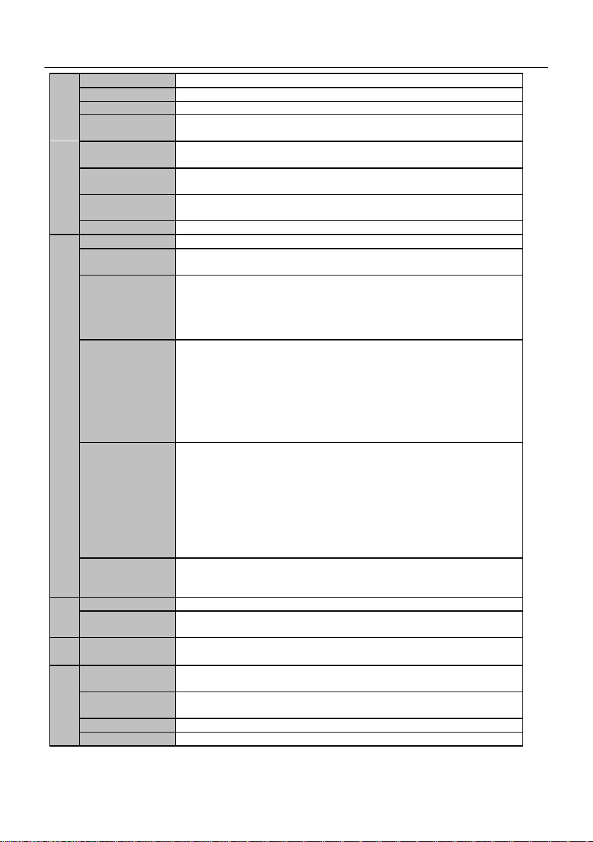
1.1 EM 760 series inverter model and specification
voltage : three - phase AC 340V ~ 460V
Applicable motor: three-phase AC asynchronous motor and permanent magnet synchronous motor
Rated supply
voltage
model
Applicable motor power
( kW)
Rated output current
( A)
phase AC
3 40 ~ 4 60 V
EM 76 0-0R7-3B
0.75
2.5
EM 76 0-1R5-3B
1.5
4.2
EM 76 0-2R2-3B
2.2
5.6
EM 76 0-4R0-3B
4.0
9.4
EM 76 0-5R5-3B
5.5
13
EM 76 0-7R5-3B
7.5
17
EM 76 0-011-3B
11
25
EM 76 0-015-3B
15
32
EM 76 0-018-3B
18.5
38
EM 76 0-022-3B _
twenty two
45
EM 76 0-030-3 /3B
30
60
EM 76 0-037-3 /3B
37
75
EM 76 0-045-3 /3B
45
90
EM 76 0-055-3 /3B
55
110
EM 76 0-075-3 /3B
75
150
Table 1- 1 Technical Specifications of EM 760 Series Frequency Converters
project
specification
power
suppl
y
Rated supply
voltage
phase 3 40 V-10% to 46 0 V+10%
50 ~ 60Hz±5%, voltage unbalance rate <3%
outpu
t
Maximum output
voltage
The maximum output voltage is the same as the input supply voltage
Output current
rating
100% rated current continuous output
Maximum overload
current
150% rated current 60s, 180% rated current 10s, 200% rated current
2s
Basic
contr
ol
funct
ions
drive mode
V/F Control (VVF);
Speed Sensorless Vector Control (SVC);
Speed Sensor Vector Control (FVC)
Input
Frequency (speed) input, torque input
Start-stop control
method
Keyboard, control terminals (two-wire control, three-wire control),
communication
Frequency control
range
0.00 to 600.00 Hz/0.0 to 3000.0 Hz
Input frequency
resolution
Digital input: 0.0 1Hz Analog input: 0.1 % of maximum frequency
Speed range
1:50 (VVF), 1:200 (SVC), 1:1000 (FVC)
Speed control
accuracy
±0.5% (VVF) , ±0.2% (SVC) , ±0.02% (FVC)
Acceleration and
deceleration time
~600.00s / 0.1s ~6000.0s / 1s ~60000s
Voltage / Frequency
The rated output voltage is adjustable from 20 % to 100 % , and the
EM760 Series High Performance Vector Drive User Guide
10
Characteristics
fundamental frequency is adjustable from 1 Hz to 600 Hz /3000 Hz
Torque boost
Fixed torque boost curve, optional V/F curve
starting torque
150%/ 3Hz (VVF), 150%/0.25Hz (SVC), 180%/0 Hz (FVC)
Torque control
accuracy
±5 % rated torque (SVC), ±3% rated torque (FVC)
Output voltage
self-adjustment
The input voltage changes, the output voltage remains basically the
same
Current automatic
limiter
Automatically limit output current to avoid frequent overcurrent
tripping
DC braking
Braking frequency: 0.01 ~Maximum frequency Braking time: 0 ~30S
Braking current: 0% to 1 5 0% of rated current
Signal input source
Communication, multi-speed, analog, high-speed pulse, etc.
enter
outpu
t
Funct
ion
reference power
10.5V ±0.5V / 20mA
Terminal control
power
24V/200mA
Digital input
terminal
7 (standard X1 ~X7) + 3 (extension card X8 ~X10 ) digital
multi-function input:
X7 can be used as high-speed pulse input terminal (F02.06=35/38/40);
X1~X6 and X8 ~X1 0 , a total of 9 channels can only be used as ordinary
digital input terminals
Analog input
terminal
3 (standard AI1~AI3) + 1 (extension card AI4) analog input:
1 channel A I1: support 0 ~ 10V or - 10 ~ 10V, optional through function
code F 02.62 ;
2 channels A I2/AI3 : support 0 ~ 10V or 0 ~ 20mA or 4 ~ 20mA, through
the function code F 02.63 ,
F 02.64 optional ;
1 channel A I4 : support 0 ~ 10V or - 10 ~ 10V, optional through function
code F 02.65
Digital output
terminal
2 (standard Y1/Y2) open-collector multi-function output+
2 channels (R1:EA/EB/EC and R2:RA/RB/RC) relay multi-function
output+
2 (expansion card) circuits (R 3: RA3/CA3 and R 4 : R A4/CA4 ) relay
multi-function output
collector output maximum output current 50mA;
Relay contact capacity 250VAC/3A or 30VDC/1A, EA-EC and RA-RC
normally open, EB-EC and RB-RC normally closed; R A3-CA3 , R A4-CA4
normally open
Analog output
terminal
2 channels (M1/M2) multi-function analog output terminals, can output
0~ 10V or 0 ~ 20mA or 4 ~ 20mA,
through function code F 03.34 and F 03.35
V
LCD display _
LCD digital tube displays the relevant information of the inverter
parameter copy
The parameter setting information of the inverter can be uploaded and
downloaded to realize fast parameter copying
Prote
ct
Protective
function
Short circuit, overcurrent, overvoltage, undervoltage, phase loss,
overload, overheating, overspeed, load loss and external fault, etc.
use
condi
tion
Installation site
Indoor, below 1km altitude, no dust, no corrosive gas and no direct
sunlight
Applicable
environment
-10 ℃~+50 ℃, 20%~90%RH ( non-condensing )
vibration
less than 0.5 g
storage
-40 ℃~+70 ℃

EM760 Series High Performance Vector Drive User Guide
11
environment
Installation
method
Wall-mounted, floor-standing electrical control cabinet,
through-wall
Protection class
IP20 /IP21 (add plastic baffle)
cooling method
forced air cooling

EM760 Series High Performance Vector Drive User Guide
12
Installation
2.1 Product confirmation
Notice
⚫Do not install damaged inverters and inverters with missing parts.
risk of injury
When you get the product, please confirm with the table below.
Confirm item
Confirmation method
Is it consistent with the item
ordered.
Check the nameplate on the side of the inverter.
Is there any damage.
Check the overall appearance and check for damage in
transit.
Check whether the fastening parts
such as screws are loose.
Check with a screwdriver if necessary.
If there is any bad situation, please contact the agent or the marketing department of our
company.
⚫nameplate
⚫Inverter model description
EM760 Series High Performance Vector Drive User Guide
13
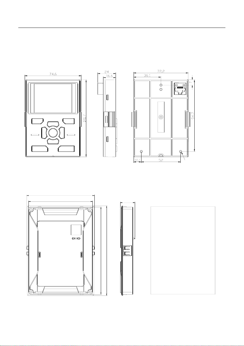
2.2 External Dimensions and Mounting Dimensions
EM760 series inverters have 15 specifications, 2 shapes and 7 installation sizes, and the
keyboard and bracket can be externally drawn. As shown in Figure 2-1 and Table 2-2.
使用自攻钉ST2.9-6.5
0.75~22kW series external keyboard size reference
104.6
110.6
23.7
142.6
146.6
安装键盘托架开孔尺寸:
143×105mm
EM760 Series High Performance Vector Drive User Guide
14
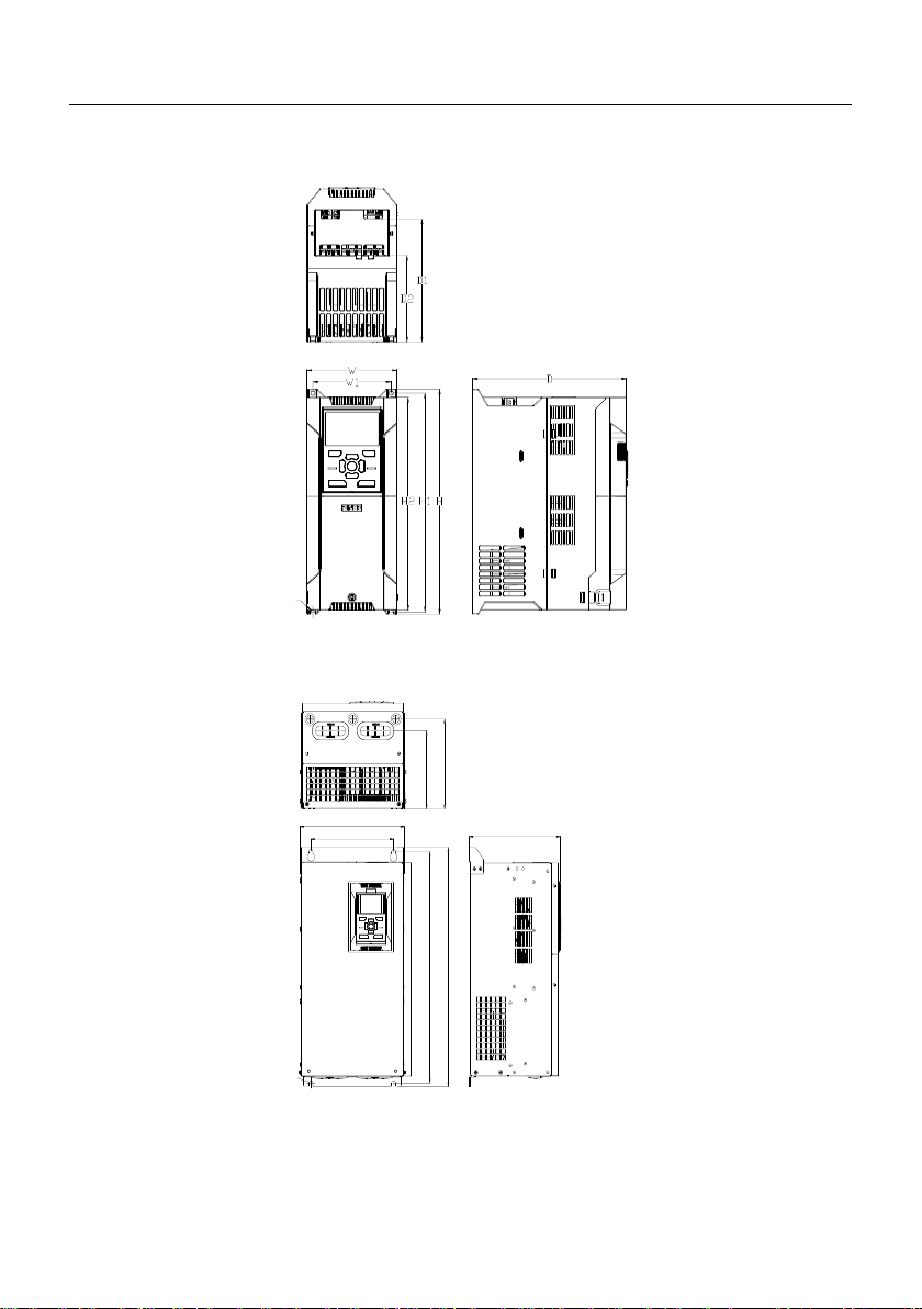
30~75kW series keyboard bracket opening dimension reference
(a) Dimensions of keyboard and bracket
d
(b) 0.75kW~22kW inverter shape
H
d
W1 D
W
D2
D1
H2
H1
(c) 30kW~75kW inverter shape
Figure 2-1 Dimensions of EM760 series inverter and keyboard

EM760 Series High Performance Vector Drive User Guide
15
Table 2-1 External dimensions and installation dimensions of EM760 series inverters
Specification
W
W1
H
H1
H2
D
D1
D2
d
shape
EM 76 0-0R7-3B
95
82
230
222
218
171
132
96
4.5
(b)
EM 76 0-1R5-3B
EM 76 0-2R2-3B
EM 76 0-4R0-3B
EM 76 0-5R5-3B
110
95
275
267
260
187
146
105
5.5
EM 76 0-7R5-3B
EM 76 0-011-3B
140
124
297
289
280
207
163
120
5.5
EM 76 0-015-3B
EM 76 0-018-3B
190
171
350
340
330
220
173
12 8
7
EM 76 0-022-3B _
EM 76 0-030-3 /3B
255
202
494
477
440
222
186
162
9
(c)
EM 76 0-037-3 /3B
EM 76 0-045-3 /3B
305
210
540
519
480
263
217
197
9
EM 76 0-055-3 /3B
EM 76 0-075-3 /3B
325
230
638
613
570
264
220
181
11.5

EM760 Series High Performance Vector Drive User Guide
16
2.3 Installation site requirements and management
installation site
The installation site should meet the following conditions:
⚫The interior is well ventilated.
⚫Ambient temperature -10 C ~ 50 C.
⚫Avoid high temperature and humidity, humidity less than 90%RH, no rain or other liquid
dripping.
⚫Please install it on a flame-retardant object such as metal, and do not install it
on a flammable object such as wood.
⚫Avoid direct sunlight.
⚫No flammable, corrosive gases and liquids, no dust, oily dust, floating fibers and
conductive dust.
⚫The installation base is firm and vibration-free.
⚫No electromagnetic interference, away from interference sources.
Precautions
During installation, please take protective measures for the inverter to prevent metal
fragments or dust generated by drilling holes from falling into the inverter. After installation,
please remove the shield.
2.4 Installation direction and space
EM760 series inverters are equipped with cooling fans for forced air cooling. In order to
make the cooling cycle effect well, the inverter must be installed in a vertical direction, and
there must be enough space for the up and down, left and right and adjacent objects or baffles
(walls), please refer to Figure 2-2 .

EM760 Series High Performance Vector Drive User Guide
17
大于150mm大于150mm
大于120mm
大于120mm
对流口
Figure 2-2 Inverter installation direction and space
2.5 Panel Removal and Installation
The EM760 series needs to remove the cover for wiring the main circuit, control circuit and
expansion card. After completing the wiring work, install the wiring duct and cover in the reverse
order of removal as shown in the illustration.
(1)EM760 series 0.75~22kW face cover removal
←按压
①用工具将下盖板螺钉拆出 ②向内按压两侧卡扣,将下
盖板倾斜向外拉出
③如使用扩展卡,则先将上
盖板固定螺钉拆出,再将键
盘网口拔出即可拆卸上盖板
Figure 2-1

EM760 Series High Performance Vector Drive User Guide
18
(2)EM760 series 30~75kW face cover removal
①用工具将面板上下两侧螺钉取下 ②用手转动面盖右侧即可打开面盖 ③转动面盖,面盖最终可转到110°左右
Figure 2-2
Wiring
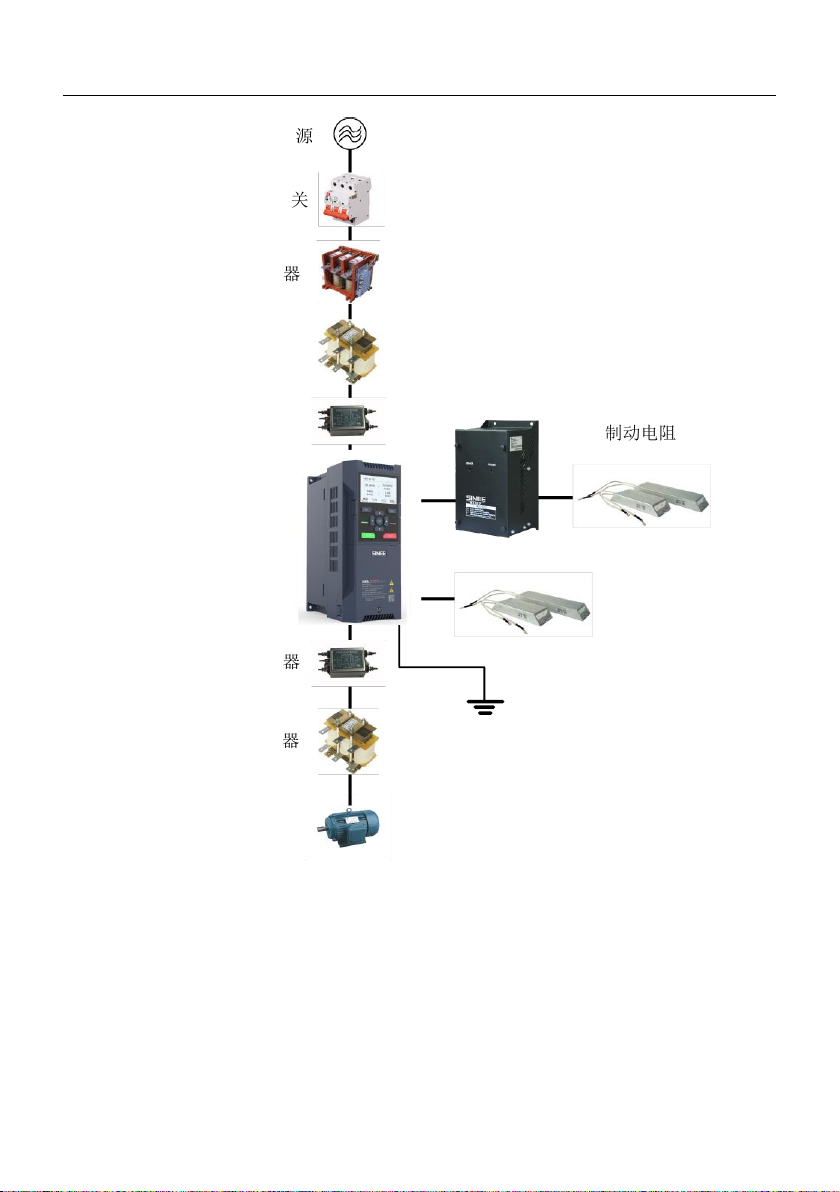
3.1 Peripheral device connection
The standard connection diagram of EM760 series inverter and peripheral equipment is shown
in Figure 3-1.
EM760 Series High Performance Vector Drive User Guide
19
Figure 3-1 Connection diagram of inverter and peripheral equipment
电源
断路器或漏电开关
接触器
交流输入电抗器
输入侧噪声滤波器
输出侧噪声滤波器
交流输出电抗器
三相电机
制动电阻
制动电阻
BR100制动单元
接地
EM760变频器

EM760 Series High Performance Vector Drive User Guide
20
3.2 Main circuit terminal wiring
3.2.1 Main circuit terminal composition
0.75-22kW main circuit terminal
30-75kW main circuit terminal
a) Schematic diagram of the main circuit terminals of medium and small power, the size of different
power is slightly different
Figure 3-2 Schematic diagram of main circuit terminal arrangement
As shown in Figure 3-3, if the 0.75-22kW inverter encounters thick cables during wiring
operation, remove the wire-passing fence of the wire-passing board.
Other manuals for EM760 Series
1
This manual suits for next models
15


