CLA-VAL VC12 User manual

CLA-VAL VC12
Electronic Controller
USER MANUAL
Leading the Innovation
PACIFIC

Table of Contents
1
Introduction .......................................................................................................................4
1.1Precautions Before Starting ...................................................................................................4
1.2Troubleshooting ..................................................................................................................... 4
1.2.1 Nothing on the OLED Display......................................................................................................... 4
1.2.2 An Input or Variable is Displayed in Red, Orange or Blue............................................................ 4
1.2.3 Issue with the Behaviour of the ValvApps™.................................................................................. 4
1.3General Disclaimer ................................................................................................................. 4
1.4Environmental Protection....................................................................................................... 4
1.5Typography............................................................................................................................. 4
2
Electrical & Mechanical Details.......................................................................................
2.1Technical Characteristics....................................................................................................... 5
3
Navigation ......................................................................................................................... 6
3.1Colour Convention ..................................................................................................................
6
6
6
6
3.2Basic VNC Software Interface Button Functionality.............................................................
3.2.1 Button Description..........................................................................................................................
3.2.2 Short Click.......................................................................................................................................
3.2.3 "Long" Button - OK click (”Home OK”) Button Only)..................................................................... 7
3.3Button Destinations................................................................................................................ 8
8
8
3.3.1 "Up/Valve Configuration"..............................................................................................................
3.3.2 "Left/Input" .....................................................................................................................................
3.3.3 "Right/Output"................................................................................................................................9
3.3.4 Information Screens....................................................................................................................... 9
3.3.5 Configuration Menus........................................................................................................................11
3.3.5.1
"Configure Inputs" Menu...........................................................................................................................11
3.3.5.2
"Configure Outputs" Menu...................................................................................................................... 13
13
14
18
23
23
25
26
29
30
25
3.3.5.3
"Valve Configuration" Menu.....................................................................................................................
3.3.5.4
Valve configuration -
"PID Menu" ............................................................................................................
3.3.5.5
"Control Curve Menu"...........................................................................................
3.3.5.6
"Totalizer Menu"...................................................................................................
3.3.5.7
"Actions Menu" .....................................................................................................
3.3.6 "Settings" Menu ............................................................................................................................
3.3.6.1
"Information" Page .........................................................................................................................
3.3.6.2
"Application Management Page...................................................................................................
3.3.6.3
"Time & Region" Page.....................................................................................................................
3.3.6.4
"Logging" Page...............................................................................................................................
5
"
Visit www.cla-valpacic.com for more details. Contact the Factory at info@cla-valpacic.com 2
CLA-VAL VC12
Electronic Controller
3.3.6.5
"Display" Page ........................................................................................................................................... 31
3.3.6.6
"Connectivity" Page ........................................................................................................................32
3.3.6.7
"Security" Page..........................................................................................................................................35
3.3.6.8
"Reboot".....................................................................................................................................................36
36
3.3.6.9
"Advanced" Pages.....................................................................................................................................
3.4In-Menu Navigation............................................................................................................... 39
3.4.1 Keyboard Functionality .................................................................................................................39
3.4.2 Numeral Selection......................................................................................................................... 39
3.4.3 Drop-Down Menu..........................................................................................................................40
4
Specific Features.............................................................................................................41
4.1Add Inputs On-The-Fly............................................................................................................
4.2Input Remap (Input Type Selection) ....................................................................................
4.3Custom Scaling......................................................................................................................
4.4Input Filtering ........................................................................................................................ 43
43
4.5Remote Configuration ...........................................................................................................
4.5.1 Register the Electronic Controller on Link2Valves......................................................................................... 43
4.5.2 Connect to Link2Valves ............................................................................................................... 44
41
42
42
Visit www.cla-valpacic.com for more details. Contact the Factory at info@cla-valpacic.com 3
CLA-VAL VC12
Electronic Controller

1 INTRODUCTION
1.1 PRECAUTIONS BEFORE STARTING
: Before usage, make sure that the latest software version is installed on your device. You can download the
latest software from: www.cla-val.ch
: This equipment must be handled with precaution. CLA-VA electronic products are robust and designed to work
under field environmental conditions, but high shocks and strong mechanical constraints can damage the equipment
and/or alter its functionality.
1.2 TROUBLESHOOTING
1.2.1 NOTHING ON THE OLED DISPLAY
A) Check if there is a proper battery connection in the Electronic Valve Controller. A low voltage (below 3.3V) could
imply having no information on the OLED display.
B) Check that the device is not in standby mode by holding the magnetic stick over the button for 5 seconds.
1.2.2 AN INPUT OR VARIABLE IS DISPLAYED IN RED, ORANGE OR BLUE
See the colour coding convention used on the Electronic Valve Controller for the inputs, outputs and variables in chapter 3.1.
1.2.3 ISSUE WITH THE BEHAVIOUR OF THE VALVAPPS™
Refer to the technical datasheet related to your ValvApps™, and especially the block diagram and the logic scheme
explaining its behaviour.
For any remaining issue, please contact CLA-VAL.
1.3 GENERAL DISCLAIMER
In accordance with our policy of continuous development and improvement, CLA-VAL reserves the right to modify or
improve its products at any time without prior notice. CLA-VAL assumes no liability or responsibility for any errors or
omissions in the content of this document.
1.4 ENVIRONMENTAL PROTECTION
Help to preserve and protect the environment. Recycle used equipment and accessories.
1.5 TYPOGRAPHY
Throughout this manual, the following typographical conventions and symbols have been adopted to help readability:
a. "Bold": Menu, command, tab and button.
b. BOLD ITALIC: Important information.
c. (1 ): Number of the reference marks on image.
d. www.cla-val.ch:Internet address.
e. : Some tips.
f. : Warning!
Visit www.cla-valpacic.com for more details. Contact the Factory at info@cla-valpacic.com 4
CLA-VAL VC12
Electronic Controller

2 ELECTRICAL & MECHANICAL DETAILS
2.1 TECHNICAL CHARACTERISTICS
Enclosure
citsalpSBA/CPtnadrateremalFlairetaM
Connections 8 (eight) SOURIAU™ UTS circular sockets to connect external sensors
1 (one) USB A connector (for external USB key)
Dmm58xWmm511xHmm471snoisnemiD
)sretem2rednuhtnom1(86PInoitcetorP
Mounting Bracket Stainless steel
Power Requirements
)senibrutPM2/PMrewoP-eLAV-ALChtiwelbitapmoc(CDV42otCDV6tupnIegatloV
Power Consumption 10 mA in stand-by, 30 mA nominal when regulating (up to 2000 mA peak
consumptions)
noitcetorpegatlov-revoCDV23noitcetorP
Reverse voltage protection
Inputs (SOURIAU Circular sockets)
Analog (AI1 to AI4) 2 (two) 0-5V (pressure sensor) & 2 (two) 4-20 mA inputs (max. voltage = 32 VDC)
Digital (DI1 to DI4) 4 (four) dry contacts inputs (max. voltage = 5 VDC @ 0.1 A, max. frequency =
100 Hz)
elbarugifnoCstinU
stigidtnacifingis)”000.0“(4ot)”0“(1tnioplamiceD
delbasidro,%99ot%1elbarugifnocretlifevitalumuCretliflangiS
stinudnatupnielbarugifnoCrezilatoT
Outputs (SOURIAU Circular sockets)
Solenoid (SO1 to SO4) 4 (four) latching or digital output (6 VDC @ 0.5 A - binary or proportional)
PID Control Parameters
Proportional Band 0% to 100% (adjustable in 1% increments - independently for opening and closing)
ot0morfelbatsujdAdnaBdaeD full-scale of set-point signal
)s1fostnemercninielbatsujda(s06ots01emiTelcyC
)s1fostnemercninielbatsujda(s06ots0dnaBlargetnI
Derivative Band 0 s to 60 s (adjustable in increments of 1 s)
senoz4otpUgninoZpooL
4otpUspooLDIP
Display & Navigation
Display 1.5"OLED display (128 x 64)
tnoc)citengam(SLI)evif(5noitagivaN acts and magnetic stick for navigation
Communication
BSU,HTOOTEULB,SRPGsecafretnI
SPTTH,PTF,CNVslocotorP
Logging
citamotuAdnalaunaMssecorP
yromemlanretnIyromeM , SD card (4 GB default), Export to USB, Export to FTP server
Logging speed 1 minute
)tamrofyrateirporp(elifVSCtamroF
Temperature Range
Working Temperature -10°C to +60°C
Storage Temperature -30°C to +60°C
Visit www.cla-valpacic.com for more details. Contact the Factory at info@cla-valpacic.com 5
CLA-VAL VC12
Electronic Controller

3 NAVIGATION
3.1 COLOUR CONVENTION
Values are usually displayed in black; however input values can sometimes be displayed in different colour’s,
depending on the status of the associated input:
Black: normal status. The value displayed is what is measured on the input
Red: loss of signal. The associated input has no signal arriving
Orange: loss of signal, and the system overrides the value
Blue: local override. The value has been manually overridden locally and the signal at the input is not taken into
account
Grey: remote signal
3.2 BASIC VNC SOFTWARE INTERFACE BUTTON FUNCTIONALITY
3.2.1 BUTTON DESCRIPTION
- Home/OK
- Left/Input
- Right/Output
- Up/Valve Configuration
- Down/Settings
Other Icons in this manual
- Short Click
- Long Click (click on button "Long")
3.2.2 SHORT CLICK
Is "Ok" or "Select" when used as a (short click)
- When used as a , the cursor moves to the left
- When used as a , the cursor moves to the right
Visit www.cla-valpacic.com for more details. Contact the Factory at info@cla-valpacic.com 6
CLA-VAL VC12
Electronic Controller

- When used as a , the cursor moves up
- When used as a , the cursor moves down
3.2.3 "LONG" BUTTON - OK CLICK ( "HOME/OK" BUTTON ONLY)
To activate the long click, click on the " Long" button, which will then be displayed in red. Clicking a second time on
will deactivate the long click and the text will be displayed in black.
From the home screen, a "Long" button activation and click on "Home/OK" will put the Electronic Valve Controller
into sleep mode.
From any other location, a "Long" button activation and click on the "Home/OK" button returns to the "Home Screen".
Visit www.cla-valpacic.com for more details. Contact the Factory at info@cla-valpacic.com 7
CLA-VAL VC12
Electronic Controller

3.3 BUTTON DESTINATIONS
3.3.1 "UP/VALVE CONFIGURATION"
A) "Short Click": View Valve Information (from Home Screen).
From the "Home Screen", on the button navigates to the "Valve Information" screen.
B) "Long button": Enter Valve Configuration Menu (from Home Screen).
From the "Home Screen", a button activation and click on the navigates to the "Valve Configuration"
screen.
3.3.2 "LEFT/INPUT"
A) "Short Click": View Input Information (from Home Screen).
From the"Home Screen" "Inputs" screen.
B) "Long button" activated - Enter Input Configuration Menu (from Home Screen).
From the "Home Screen", a button activation and click on the navigates to the "Configure Inputs" screen.
, a on the navigates to the
Visit www.cla-valpacic.com for more details. Contact the Factory at info@cla-valpacic.com 8
CLA-VAL VC12
Electronic Controller

3.3.3 "RIGHT/OUTPUT"
A) "Short Click": View Output Information (from Home Screen).
From the "Home Screen", a on the navigates to the "Outputs" screen.
B) "Long Button" activated: Enter Output Configuration Menu (from Home Screen).
From the"Home Screen", a activation and click on the navigates to the "Configure Outputs" screen.
Menu Locations
3.3.4 INFORMATION SCREENS
Visit www.cla-valpacic.com for more details. Contact the Factory at info@cla-valpacic.com 9
CLA-VAL VC12
Electronic Controller

A) "Inputs": The Inputs menu displays all of the activated inputs in current use by the selected ValveApps™.
B) "Outputs":The outputs menu displays all of the activated outputs in current use by the selectedValveApps™ .
C) "Schematics": The Schematics menu displays the simplified valve schematics for a given ValveApps™ and the
connected inputs and outputs.
A) "Display Panel": The Display Panel displays all of the activated variables in current use by the selected ValveApps™ .
Visit www.cla-valpacic.com for more details. Contact the Factory at info@cla-valpacic.com 10
CLA-VAL VC12
Electronic Controller

3.3.5 CONFIGURATION MENUS
: The "Configuration" screens are accessed with a "long button" from the "Home Screen".
3.3.5.1 "Configure Inputs" Menu
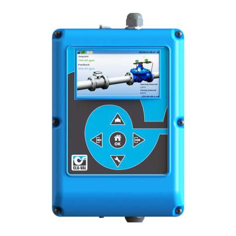
A"short click" on "Left/Input" from the"Configure Inputs" screen enters the configuration of the selected input.
Input Field Descriptions:
"Display Name": Use this field to choose a unique name for each input.
"Units": Choose from the following available units:
o (gpm) - Gallon per minute [flow];
o (mgd) - Mega Gallons per day [flow];
o (cfm) - Cubic Feet per minute [flow];
o (cfs) - Cubic feet per second [flow];
o (l/min) - Litres per minute [flow];
o (l/s) - Litres per second [flow];
o (m3/h) - Cubic meters per hour [flow];
o (Ml/d) - Mega litres per day [flow];
o (Imp gpm) - Imperial Gallons per minute [flow];
o (bar) - Bar [pressure];
Visit www.cla-valpacic.com for more details. Contact the Factory at info@cla-valpacic.com 11
CLA-VAL VC12
Electronic Controller

o (kPa) - Kilopascals [pressure];
o (Mld) – Mega Litres per day [flow];
o (psi) - Pounds per square inch[pressure];
o (m) - Meters of water [pressure];
o (in) - Inches of water [pressure];
o (ft) - Feet of water [pressure];
o (%) - Percentage [unit-less];
o (h) - Hours [time];
o (min) - Minutes [time];
o (s) - Seconds [time];
o (gal) - Gallons [volume];
o (mg) - Mega gallons [volume];
o (cf) - Cubic feet [volume];
o (l) - Litres [volume];
o (m3) - Cubic meters [volume];
o (Ml) - Mega liters [volume];
o (mA) - Milliamps [electrical flow];
o (Volt) - Volts [electrical potential];
"Decimal": Select from available decimal places:
o 0
o 0.0
o 0.00
"Signal Type": Select from available signal types:
o4-20 mA
o0-5 V (pressure sensor)
"4mA = ": Set the value of the input at 4 mA; usually this will correspond to a value of 0.
"20mA = ": Set the value of the input at 20 mA; this should correspond to the maximum measured value.
"0V = ": Set the value of the input at 0 V; usually this will correspond to a value of 0.
"5V = ": Set the value of the input at 5 V; this should correspond to the maximum measured value.
"Signal Filter": Select a filter length between 1% and 99%. This is a cumulative filter, where the value corresponds to
the weight of the previous sample. The higher the value, the higher the filtering effect. A 0% value will inactivate
the filter.
"Lost Signal (< 3.6 mA) ":This menu designates which action the controller will take in the event that a signal
falls below 3.6 mA, usually when there is a power outage or when the 4-20 mA loop has been broken.
o“Default Value”: This option allows the user to input a value to be inserted when the 4-20mA input signal has
been lost.
o“Keep Value”: This option allows the user to specify that the last input value received by the controller will be the
value that is used once the signal is lost.
o“Do nothing” This option will specify that no action is taken by the controller when an input signal is lost.
"Use as RSP/LSP":When this box is checked, the input is treated as an RSP/LSP - Remote Set Point / Local Set
Point. This allows the input to be seen in the Display Panel (short click down - + ) and allows Actions to be
taken when the Remote Set Point is changed or overridden.
"Display on home page":When this box is checked, the input is shown on Display panel.
"Menutools ":Click on this button to calibrate the pressure sensor.
Visit www.cla-valpacic.com for more details. Contact the Factory at info@cla-valpacic.com 12
CLA-VAL VC12
Electronic Controller
Power Management
. To calibrate the pressure sensor properly, it must be disconnected from the valve in order to read atmosphere
pressure.
3.3.5.2 "Configure Outputs" Menu
A"short click" on "Right/output" from the "Configure Outputs" screen enters the configuration of the selected
output.
Solenoid Output (SO) Field Descriptions:
"Display Name": Use this field to choose a unique name for each output.
"Type":
o
“CVM/CVP” its PWM output (Pulse Width Modulation): this is the industry trade name for the management of
pulses sent to the opening/closing CVM/CVP pilots.
o
“Latching Output 1/0”: Provide a pulse for 200ms by default open (1) or close (0) the bistable solenoid.
o
“Digital 1/0”: Specifies that the output is either open or closed for the time specified in the boxes below.
Its use to provide power supply on CVM/CVP pilots (6VDC).
"Cycle Time":
The amount of time for one complete cycle of action for the opening/closing CVM/CVP pilots.
"Default Value": The default active time of the CVM/CVP pilots during the cycle.
"Display on home page": When this box is checked, the input is shown on Display panel.
3.3.5.3 "Valve Configuration"Menu
The "Valve Configuration"screen includes the regulation blocks related to the loaded
ValvApps™
.
Regulation blocks can be of the following types:
Visit www.cla-valpacic.com for more details. Contact the Factory at info@cla-valpacic.com 13
CLA-VAL VC12
Electronic Controller
PID (Proportional-Integral-Derivative):
The "PID" regulation maintains the valve at a configured set-point. Up to four (4) "PID"
regulation loops can be
programmed, each of them offering local or remote set-point capability. Real-time chart view helps to visualize valve
response and fine tune the Electronic Valve Controller accordingly. Perfect valve control is achieved by CLA-VAL
features such as programmable set-point ramping to prevent hydraulic shocks.
Control Curve:
The "Control Curve" offers an easy way to create a relationship between 2 system variables. Using graphical functions
the user draws the
"Control Curve"
relationship linking pressure,flow, level and/or time directly on the Electronic Valve
Controller screen. Up to four (4)
"Control Curves"
can be profiled allowing specific adaptation such as seasonal
adjustment.
!ACTION!:
Used to take action (or alarms) when a programmable condition is met by forcing an output (relay, solenoid,
4-20 mA). The closing relay can be used to send an alarm to a supervision system. Up to four (4)"!Actions! " can be
programmed including appropriate hysteresis or dead band configuration.
Power Management:
This is used to manage the unit Power and prevent excessive battery discharge. It can be used on flow or differential
pressure.
The power management allows activating default values, according to user pre-programmed rules.
Valve configuration - "PID Menu"
A) General Tab
Input Field Description:
"PID Description": Use this field to choose a unique name for each PID loop
"PID Type ": Designate what type of control is being used
o
"Flow": Control using flow SetPoint and Feedback
o
"Pressure ": Control using pressure SetPoint and Feedback
3.3.5.4
Visit www.cla-valpacic.com for more details. Contact the Factory at info@cla-valpacic.com 14
CLA-VAL VC12
Electronic Controller

o
"Level": Control using level SetPoint and Feedback
o
"%": Control using percentage open (position of the valve) SetPoint and Feedback
o
"Analog": Control using flow SetPoint and Feedback
"PID Cycle every (s)": This field designates how often the calculation will be performed to determine the appropriate
action to be taken with the output, minimum value is 10 seconds
"Signal loss ": This field designates what action the controller will take when there is a loss of signal on the Remote Set
Point (RSP). The options are:
o
"No Action"
o
"Open 100%": Open valve 100%
o
"Close 100%": Close valve 100%
o
"Lock Position ": Maintain valve in current position
"PID Status": The user may configure a PID loop, but not activate it until the appropriate time. The choices are:
o
"On"
o
"Off"
o
"Conditional": When the"Conditional" option is chosen, an additional field appears and prompts the user to
specify when the PID should be active. The following field is shown:
The PID loop can be configured to be always active, or when one of the inputs meets a certain condition. In this
case, use the pull down menu that is defaulted to "Always" to select the appropriate input, then use the pull down
menu to the right to select an operator, such as the "Greater than" sign (>), then specify a value.
Example: The following PID loop has been set to be conditional active, only when the Feedback [AI2] is greater
than 50.00 l/s.
B) Input Tab
Input Field Description:
Setpoint Section:
o
"Source": Designates which compatible input or variable is to be used as the SetPoint for the PID loop
o
"Current Value": Shows the *live* current value of that input
o
"Override": Allows the user to input an override value from this menu rather than having to go back to the input
information or input configuration screens - this can be helpful when commissioning a system for the first time
Visit www.cla-valpacic.com for more details. Contact the Factory at info@cla-valpacic.com 15
CLA-VAL VC12
Electronic Controller
o
"Ramping (l/s/min) ": Increases or decreases the set point over period x when a new set point is entered to help
prevent overshoot or undershoot of the target value. [either by "Remote Set Point" Changes or "Local Set Point"
(override) changes]
Feedback Section:
o
"Source": Designates which input is to be used as the feedback for the PID loop
o
"Current Value": Shows the *live* current value of that input
o
"Override": Allows the user to input an override value from this menu rather than having to go back to the input
information or input configuration screens - this can be helpful when commissioning a system for the first time
C) Output Tab
Input Field Description:
"Output Type": Designates what type of output is used.
o
"CVM/CVP": Uses solenoid output (1 or 2) to control the pilot, according to the PID regulation
"Cycle Time (s)": Designates the total cycle of action for the "CVM/CVP" command
o
"Output limit (%)": Designates valve opening/closing limit
D) Adjustment Tab
Input Field Description:
"Zone Number": Designates which PID loop is being adjusted; at any time, up to 4 PID loops may be used
"Closing Speed (%) ": Designates how quickly the valve will be able to close. 1% is the slowest possible, 99% is the
fastest possible
NOTE: The actual time to close will depend on the hydraulic conditions.
"Opening Speed (%)": Designates how quickly the valve will be able to open. 1% is the slowest possible, 99% is the
fastest possible
Visit www.cla-valpacic.com for more details. Contact the Factory at info@cla-valpacic.com 16
CLA-VAL VC12
Electronic Controller
NOTE: Actual time to open will depend on the hydraulic conditions.
"Deadband (l/s)": Designates where the controller will take no action because it is close to the SetPoint.
Example: If the setpoint is 50 l/s and the deadband is set at 2 l/s, then the controller will take no action on
the feedback value from 48 l/s to 52 l/s
"Integral (s)": This value is used for fine tuning of very sensitive systems
It is not recommended that this be used without contacting CLA-VAL Technical Support!
"Derivative (s)": This value is used for fine tuning of very sensitive systems
It is not recommended that this be used without contacting CLA-VAL Technical Support!
E) Zoning Tab
Input Field Description:
"Number of zones": Designates how many PID zones are to be created
NOTE: When multiple PID loops are created, the active region for each is designated by an equal division of the
total feedback range, see example below:
The active region for zones 1, 2 and 3 are each one third of the total feedback range. These values can be specified by
changing the values in each zone, according to the needs of the user.
Zone 1: designates the top of the range for zone 1 (bottom range is bounded by the low level of the feedback scale).
Zone 2: designates the bottom and top range for zone 2.
Zone 3: designates the bottom range for zone 3 (top of the range is bounded by the high level of the feedback scale).
Visit www.cla-valpacic.com for more details. Contact the Factory at info@cla-valpacic.com 17
CLA-VAL VC12
Electronic Controller
3.3.5.5 Valve configuration - "Control Curve Menu"
A) General Tab
Input Field Description:
"CC Description ": Designate a name for the custom control curve
"CC Status": Designate whether the control curve is active
o
"On": The control curve is active
o
"Off ": The control curve is inactive
o
"Calendar": The control curve is activated according to calendar rules, which are defined in the"Activation" tab
o
"Conditional": Condition based on an input or variable, as defined in the "Active when"field
"Active when": Designate the rule for the conditional activation
B) Activation Tab (only for calendar activation)
Input Field Description:
"Day of the week": Designates which day(s) of the week the custom control curve is active
"Week of the year": Designates which months the selected days are active
Visit www.cla-valpacic.com for more details. Contact the Factory at info@cla-valpacic.com 18
CLA-VAL VC12
Electronic Controller
C) In/Out Tab
Input Field Description:
"Input" Section:
"Source": Designate the input flow signal location
"Output" Section:
"Destination": Designate the analog output location for the motorized control
"Override": Override the output in "Designation" with a custom value
Visit www.cla-valpacic.com for more details. Contact the Factory at info@cla-valpacic.com 19
CLA-VAL VC12
Electronic Controller
D) R/T view Tab
This screen describes the relationship between 2 system variables in relation to the X and Y axis.
The arrow located at the bottom-left corner shows the user which way to read the graph:
1. Standard: the input is on the X-axis (in this case, flow) and the output on the Y-axis (in this case, actuated pilot
command for a targeted downstream pressure).
This screen illustrates that as the flow increases, the motorized control pilot will increase the output pressure according to
the graph.
2. Reverse: the input is on the Y-axis (in this case, Reservoir/Tank Level) and the output on the X-axis (in this case,
Target Flow)
This screen describes that as the reservoir level decreases, the targeted flow (to fill the reservoir) increases, and the
motorized control will act accordingly.
: The light on the bottom right of the screen indicates whether the control curve is active (green light) or inactive (red
light).
Visit www.cla-valpacic.com for more details. Contact the Factory at info@cla-valpacic.com 20
CLA-VAL VC12
Electronic Controller
Other manuals for VC12
1
Table of contents
Other CLA-VAL Controllers manuals

CLA-VAL
CLA-VAL 34 Series Owner's manual

CLA-VAL
CLA-VAL CDS6 Owner's manual

CLA-VAL
CLA-VAL CF1 Series Owner's manual

CLA-VAL
CLA-VAL D35 User manual

CLA-VAL
CLA-VAL CF1-C1 User manual

CLA-VAL
CLA-VAL 130VC-2 Owner's manual

CLA-VAL
CLA-VAL 90G-21 Instruction manual

CLA-VAL
CLA-VAL CDS7-DO Instruction manual

CLA-VAL
CLA-VAL CPC Owner's manual

CLA-VAL
CLA-VAL e-Drive-34 User manual