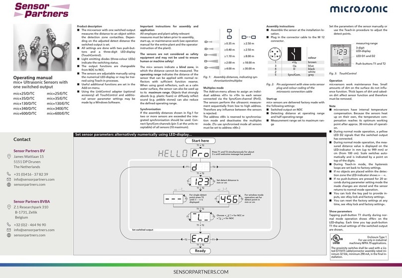
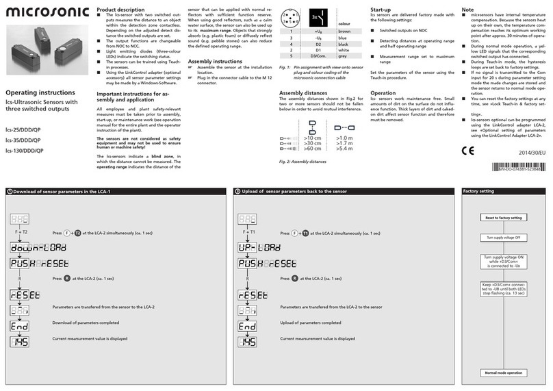
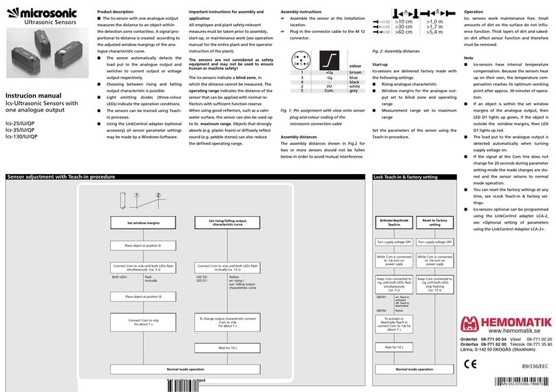
manuals.online logo
Brands
  1. Home
  2. •
  3. Brands
  4. •
  5. Microsonic
  6. •
  7. Accessories
  8. •
  9. Microsonic pms-15/CI/A1 User manual

Microsonic pms-15/CI/A1 User manual

Operating Instructions
Ultrasonic sensor with one
analogue output
pms-15/CI/A1 pms-15/CU/A1
pms-25/CI/A1 pms-25/CU/A1
pms-35/CI/A1 pms-35/CU/A1
pms-100/CI/A1 pms-100/CU/A1
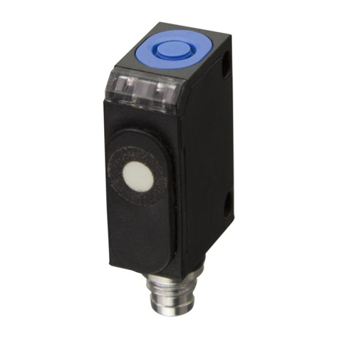
Product Description
The pms sensor has a stainless steel
housing and is designed for applica-
tions with hygienic requirements.
The ultrasonic transducer surface of
the pms sensors is laminated with a
PTFE film (Teflon film). The transdu-
cer itself is sealed against the hous-
ing by a joint ring.
The pms sensor with a D12 adapter
shaft can be fitted in a mounting clip
which meets hygiene standards like the
sensor screw connection BF-pms/A1.
The special housing design ensures
that any cleaning fluids are able to
run off completely, regardless of the
intstallation situation.
The pms sensor is ECOLAB certified.
The pms sensor variant D12 adapter
shaft offers a non-contact measure-
ment of the distance to an object
Sensor adjustment with Teach-in procedure
Set window
margins
Place object
at position 
Connect Com for
about 3 s to +UB
Place object
at position 
Connect Com for about
1 s to +UB
Set rising/falling output
characteristic curve
Connect Com for
about 13 s to +UB
To change output
characteristic connect
Com for about 1 s to +UB
Reset to factory setting
Switch off power supply
While Com is connected to -UBswitch
on
power supply
Keep Com connected to
-UBfor about 13 s, until both LEDs stop
flashing
Disconnect Com from -UBbefore switch-
ing off power supply
Normal operating mode
Wait for about 10 s
Normal operating mode
present within the sensor’s detection
zone. Depending on the set window
limits, a distance-proportional ana-
logue signal is the result.
For sensor setting, the accessory
LinkControl adapter LCA-2 is recom-
mended in combination with Link-
Control software for Windows©. Al-
ternatively, the sensor can also be set
by Teach-in via pin 2.
Safety Notes
Read the operating instructions
prior to start-up.
Connection, installation and
adjustment works should be car-
ried out by expert personnel only.
No safety component in
accordance with the EU Machine
Directive.
Proper use
pms ultrasonic sensors are used for
non-contact detection of objects.
The sensor must be mounted in an
EHEDG-approved mounting clip,
such as the sensor screw connection
BF-pms/A1 for a EHEDG-complaint
use.
Installation
Assemble the sensor and its hygie-
nic D12 sensor screw connection
BF-pms/A1 or an equivalent sensor
mounting clip at the installation
location.
Pull sensor cable through the sen-
sor gland, connect it to the M8
sensor plug.
Push the sensor with its shaft into
the sensor screw connection BF-
pms/A1 and adjust (see figure 3-
5). Tighten with lock nut (maxi-
mum tightening torque 12 Nm).
Start-Up
Connect the power supply.
Carry out the sensor adjustment
with LinkControl or alternatively
Teach-in procedure in accordance
with the diagram.
Fig. 1: Pin assignment with view onto sensor
plug and colour coding of the
microsonic connection cable
Factory Setting
Rising analogue characteristic
curve between the blind zone and
the operating range.
Maintenance
microsonic sensors are maintenance-
free. For cleaning in areas with hygi-
enic requirements, access to the sen-
sor must be guaranteed from all
sides. Cleaning is permitted up to a
cleaning temperature of 85°C. Do
not use a high-pressure cleaner to
clean the sensor.
Fig. 2: Assembly distances to avoid a mutual
influence of the sensors
Notes
The sensors of the pms family
have a blind zone. Within this
zone a distance measurement is
not possible.
If several pms sensors are operated
in a small space, the minimum
1
3
colour
+UB
-UB
brown
blue
4
2
I|U
Com
black
white
1
4
3
2
pms-15..
pms-25..
pms-35..
≥0.25 m
≥1.30 m
≥0.35 m
≥2.50 m
≥0.40 m
≥2.50 m
pms-100..
≥0.70 m
≥4.00 m
mounting for parallel or opposite
arrangement of the sensors shown
in figure 2 must be maintained.
The pms sensors are equipped
with an internal temperature com-
pensation. Due to the sensors self
heating, the temperature compen-
sation reaches its optimum
working-point after approx. 45
seconds of operation.
The sensor can be reset to its fac-
tory setting (see »Further set-
tings«).
For Teach-in procedure when us-
ing the LinkControl adapter (op-
tional accessory) the additional
adapter 5G/M12-4G/M12/M8 is
needed.
If the sensor is cleaned wet during
operation, all surfaces must be in-
clined at least 3° from the hori-
zontal alignment so that the clea-
ning agents can run off completely
(see figure 3).
Fig. 3: pms sensor D12-adapter shaft with
sensor screw connection BF-pms/A1,
all surfaces must be inclined at
least 3°.
■The D12 adapter shaft of the pms
sensor has to stick out at least
6 mm from the screw connection
(see figure 5).
The sealing ring has to fill space
between D12 sensor shaft and cap
nut. Sealing ring should not to be
pressed out excessively from the
shaft gland.
Set analogue output
Further settings
3°min.
Technical data
blind zone
operating range
maximum range
angle of beam spread
20 mm
150 mm
30 mm
250 mm
250 mm
See detection zone
350 mm
See detection zone
transducer frequency
resolution
reproducibility
380 kHz
0.069 mm
320 kHz
0.069 mm to 0.10 mm, depending on the
± 0.15 %
analogue window
± 0.15 %
accuracy
detection zones
for different objects:
The dark grey areas are determined with a
round bar and indicate the typical operating
range of a sensor. In order to obtain the light
grey areas, a plate (100 x 100 mm) is
introduced into the beam spread from the side.
In doing so, the optimum angle between
plate and sensor is always employed.
This therefore indicates the maximum
detection zone of the sensor.
It is not possible to evaluate ultrasonic
reflections outside this area.
no-load current consumption
operating voltage ripple
± 1 % (Temperature drift internal compensated)
< 40 mA
±10 %
< 40 mA
±10 %
housing
ECOLAB
stainless steel 1.4404/316L;
ultrasonic transducer: PTFE, FKM
stainless steel 1.4404/316L;
ultrasonic transducer: PTFE, FKM
yes yes
class of protection to EN 60 529
norm conformity
Type EL Class I AUX
IP 66, IP 67, IP 68
Type EL Class I AUX
IP 66, IP 67, IP 68
EN 60947-5-2
EN 60947-5-2
type of connection
controls
programmable
4-pin M8 initiator plug
Teach-in via pin 2 (Com)
4-pin M8 initiator plug
Teach-in via pin 2 (Com)
Teach-in, LinkControl
cleaning temperature
operating temperature
storage temperature
weight
to +85°C
-25°C to +70°C
to +85°C
-25°C to +70°C
-40°C to +85°C
110 g
-40°C to +85°C
110 g
response time 1)
time delay before availability 1)
analogue output 4-20 mA
24 ms
< 300 ms
24 ms
< 300 ms
RL≤500 Ω, rising/falling characteristic
operating voltage UB
order no.
10 - 30 V DC for RL≤100 Ω,
20 - 30 V DC for RL> 100 Ω,
10 - 30 V DC for RL≤100 Ω,
20 - 30 V DC for RL> 100 Ω,
terminal reverse polarity protected
pms-15/CI/A1
terminal reverse polarity protected
pms-25/CI/A1
analogue output 0-10 V
operating voltage UB
RL≥100 kΩ, short circuit proof,
rising/falling characteristic
15 - 30 V DC, terminal reverse polarity protected
rising/falling characteristic
15 - 30 V DC, terminal reverse polarity protected
order no.
1) Can be programmed with LinkContol
pms-15/CU/A1
pms-25/CU/A1
65 mm
350 mm
120 mm
1,000 mm
600 mm
See detection zone
1,300 mm
See detection zone
400 kHz
0.069 mm to 0.17 mm, depending on the
200 kHz
0.069 mm to 0.38 mm, depending on the
analogue window
± 0.15 %
analogue window
± 0.15 %
± 1 % (Temperature drift internal compensated)
< 40 mA
±10 %
< 40 mA
±10 %
stainless steel 1.4404/316L;
ultrasonic transducer: PTFE, FKM
stainless steel 1.4404/316L;
ultrasonic transducer: PTFE, FKM
yes yes
Type EL Class I AUX
IP 66, IP 67, IP 68
Type EL Class I AUX
IP 66, IP 67, IP 68
EN 60947-5-2
EN 60947-5-2
4-pin M8 initiator plug
Teach-in via pin 2 (Com)
4-pin M8 initiator plug
Teach-in via pin 2 (Com)
Teach-in, LinkControl
to +85°C
-25°C to +70°C
to +85°C
-25°C to +70°C
-40°C to +85°C
110 g
-40°C to +85°C
110 g
48 ms
< 300 ms
60 ms
< 300 ms
RL≤500 Ω, rising/falling characteristic
10 - 30 V DC for RL≤100 Ω,
20 - 30 V DC for RL> 100 Ω,
10 - 30 V DC for RL≤100 Ω,
20 - 30 V DC for RL> 100 Ω,
terminal reverse polarity protected
pms-35/CI/A1
terminal reverse polarity protected
pms-100/CI/A1
RL≥100 kΩ, short circuit proof,
rising/falling characteristic
15 - 30 V DC, terminal reverse polarity protected
rising/falling characteristic
15 - 30 V DC, terminal reverse polarity protected
pms-35/CU/A1
pms-100/CU/A1
1 analogue output
1
2
4
3
+U
B
-U
B
Com
UR
L
U | I
pms-15...
pms-25...
8cm
4cm
0cm
4cm
8cm
0cm
4cm
8cm
12cm
16cm
20cm
24cm
Rohrø10mm
ausgerichtetePlatte
Plate
Rohr ø 10 mm
8 cm
0 cm
4 cm
8 cm
4 cm
8cm
4cm
0cm
4cm
8cm
0cm
4cm
8cm
12cm
16cm
20cm
24cm
Rohrø10mm
ausgerichtetePlatte
Round bar ø 10 mm
8 cm
0 cm
4 cm
8 cm
4 cm
0 cm
4 cm
8 cm
12 cm
16 cm
20 cm
24 cm
0 cm
5 cm
10 cm
15 cm
20 cm
25 cm
30 cm
35 cm
Plate
Round bar ø 10 mm
10 cm
5 cm
0 cm
5 cm
10 cm
pms-35...
pms-100...
0 cm
10 cm
20 cm
30 cm
40 cm
50 cm
60 cm
Plate
Round bar ø 27 mm
20 cm
10 cm
0 cm
10 cm
20 cm
35 cm
0 m
0,2m
0,8 m
1,0 m
1,3 m
0,4 m
0 m
0,4 m
0,6 m
0,4 m
1,0 m
1,4 m
0,2 m
0,2 m
Round bar ø 27 mm
Plate
microsonic GmbH / Phoenixseestraße 7 / 44263 Dortmund / Germany / T+49 231 975151-0 / F+49 231 975151-51 / E[email protected] / Wmicrosonic.de
The content of this document is subject to technical changes. Specifications in this document are presented in a descriptive way only. They do not warrant any product features.
*B12713*
MV-DO-187460-589867
Fig. 4: Mounting of pms sensor with sensor
screw connection BF-pms/A1
Fig. 5: Mounting of pms sensor with sensor
screw connection BF-pms/A1
Mounting accessory
D12 sensor screw connection
BF-pms/A1
Accessory for programming
LinkControl adapter LCA-2
Adapter 5G/M12-4G/M12/M8
Sensorschaft
sensor shaft
Sensorleitung
sensor cable
Sensorverschraubung
sensor gland
6min.
2014/30/EU

This manual suits for next models

7

Other Microsonic Accessories manuals

Microsonic Trans-O-Prox III User manual

Microsonic

Microsonic Trans-O-Prox III User manual

Microsonic micplus35/DIU/TC User manual

Microsonic

Microsonic micplus35/DIU/TC User manual

Microsonic zws-15/CD/HV/QS User manual

Microsonic

Microsonic zws-15/CD/HV/QS User manual

Microsonic lcs+340/F User manual

Microsonic

Microsonic lcs+340/F User manual

Microsonic crm+25/D/TC/E User manual

Microsonic

Microsonic crm+25/D/TC/E User manual

Microsonic mic+ Series User manual

Microsonic

Microsonic mic+ Series User manual

Microsonic nano-15/CI User manual

Microsonic

Microsonic nano-15/CI User manual

Microsonic lcs+340/DD User manual

Microsonic

Microsonic lcs+340/DD User manual

Microsonic lcs-25/DD/QP User manual

Microsonic

Microsonic lcs-25/DD/QP User manual

Microsonic mic+ Series User manual

Microsonic

Microsonic mic+ Series User manual

Microsonic hps+25/DD/TC/E/G1 User manual

Microsonic

Microsonic hps+25/DD/TC/E/G1 User manual

Microsonic Ics Series User manual

Microsonic

Microsonic Ics Series User manual

Microsonic mic+25/IU/TC User manual

Microsonic

Microsonic mic+25/IU/TC User manual

Microsonic crm plus 25/DIU/TC/E User manual

Microsonic

Microsonic crm plus 25/DIU/TC/E User manual

Microsonic Ics-25/IU/QP User manual

Microsonic

Microsonic Ics-25/IU/QP User manual

Microsonic zws-15/CD/QS User manual

Microsonic

Microsonic zws-15/CD/QS User manual

Microsonic lcs-25/DDD/QP User manual

Microsonic

Microsonic lcs-25/DDD/QP User manual

Microsonic pico+15/TF/F User manual

Microsonic

Microsonic pico+15/TF/F User manual

Popular Accessories manuals by other brands

Goobay 60656 user manual

Goobay

Goobay 60656 user manual

Topcom CF-201 user guide

Topcom

Topcom CF-201 user guide

turck RU600 Series manual

turck

turck RU600 Series manual

SICK KTS-WB61141142 Series manual

SICK

SICK KTS-WB61141142 Series manual

ITOH DENKI POWER MOLLER PLUS F-RAT-NX75 manual

ITOH DENKI

ITOH DENKI POWER MOLLER PLUS F-RAT-NX75 manual

Sunbeam Sleep Perfect BL51 user guide

Sunbeam

Sunbeam Sleep Perfect BL51 user guide

O3 ehanddryers Sterizen X4 Install & Operation Manual

O3

O3 ehanddryers Sterizen X4 Install & Operation Manual

Panasonic KX-HNS104 installation guide

Panasonic

Panasonic KX-HNS104 installation guide

Delta-T WET150 user manual

Delta-T

Delta-T WET150 user manual

Mitsubishi Electric IQSS-R-E Reference manual

Mitsubishi Electric

Mitsubishi Electric IQSS-R-E Reference manual

GEM PBT-211UK Specification sheet

GEM

GEM PBT-211UK Specification sheet

Lencore i.Net G3475 user guide

Lencore

Lencore i.Net G3475 user guide

Zoom U-24 Operation manual

Zoom

Zoom U-24 Operation manual

Vox JamVOX Installation & setup guide

Vox

Vox JamVOX Installation & setup guide

MEFE CAT 673031 installation manual

MEFE

MEFE CAT 673031 installation manual

ASTRO-PHYSICS Mach1GTO manual

ASTRO-PHYSICS

ASTRO-PHYSICS Mach1GTO manual

STEINEL PROFESSIONAL IS 3360 MX COM1 Information

STEINEL PROFESSIONAL

STEINEL PROFESSIONAL IS 3360 MX COM1 Information

Foxtron DALImiw30 user manual

Foxtron

Foxtron DALImiw30 user manual

manuals.online logo
manuals.online logoBrands
  • About & Mission
  • Contact us
  • Privacy Policy
  • Terms and Conditions

Copyright 2025 Manuals.Online. All Rights Reserved.