manuals.online logo
Brands
  1. Home
  2. •
  3. Brands
  4. •
  5. Amazone
  6. •
  7. Farm Equipment
  8. •
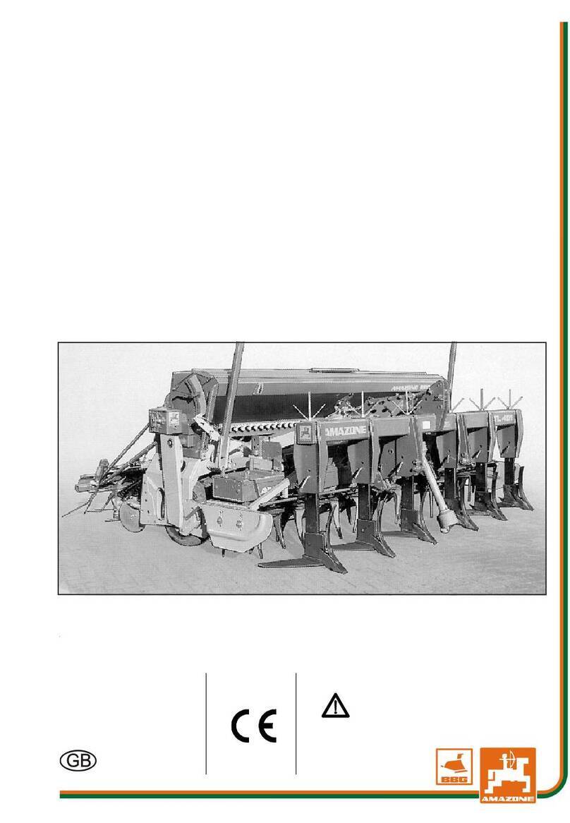
  9. Amazone Cirrus 03 User manual

Amazone Cirrus 03 User manual

Operating manual
az
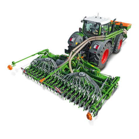
Large area seed drill
Cirrus 03
MG6382
BAH0101.08 05.2022
Please read this
operating manual
before initial operation.
Keep it in a safe place for future
use.
en
Cirrus 03 BAH0101.08 05.2022 3
Identification data
Please enter the identification data of the implement. The identifica-
tion data can be found on the rating plate.
Machine type:
Implement number, ten digits:
Year of manufacture:
Permissible total weight [kg] / [lb]:
Manufacturer address
AMAZONEN-WERKE
H. DREYER SE & Co. KG
Postfach 51
D-49202 Hasbergen
Tel.: + 49 (0) 5405 501-0
E-mail: [email protected]
Spare Parts Order
Spare parts lists are freely accessible in the spare parts portal at
www.amazone.de.
Please send orders to your AMAZONE dealer.
Formalities of the operating manual
Machine type: Cirrus 03
Document number: MG6382
Compilation date: 05.2022
¤Copyright AMAZONEN-WERKE H. DREYER SE & Co. KG, 2022
All rights reserved.
Reprinting, even of sections, permitted only with the approval of
AMAZONEN-WERKE H. DREYER SE & Co. KG.
4 Cirrus 03 BAH0101.08 05.2022
Foreword
Dear Customer,
You have chosen one of the quality products from the wide product range of AMAZONEN-WERKE,
H. Dreyer SE & Co. KG. We thank you for your trust in our products.
On receiving the implement, check to see if it has been damaged during transport or if parts are
missing. Using the delivery note, check that the implement has been delivered in full, including any
special equipment ordered. Damage can only be rectified if problems are claimed immediately.
Before initial operation, read and comply with the information in this operating manual, and particularly
the safety instructions. Only after careful reading will you be able to benefit from the full scope of your
newly purchased implement.
Please ensure that all the implement operators have read this operating manual before they put the
implement into operation.
If there are any questions or problems, please read this operating manual or contact your local service
partner.
Regular maintenance and timely replacement of worn or damaged parts increases the service life of
your implement.
Cirrus 03 BAH0101.08 05.2022 5
1User information........................................................................................13
2General Safety Information.......................................................................14
2.1Obligations and liability..........................................................................................................14
2.2Representation of safety symbols..........................................................................................16
2.3Organisational measures.......................................................................................................17
2.4Safety and protective equipment...........................................................................................17
2.5Informal safety measures.......................................................................................................17
2.6User training...........................................................................................................................18
2.7Safety measures in normal operation....................................................................................19
2.8Danger from residual energy .................................................................................................19
2.9Maintenance and repair work, fault elimination .....................................................................19
2.10Design changes .....................................................................................................................19
2.10.1Spare and wear parts and aids..............................................................................................20
2.11Cleaning and disposal............................................................................................................20
2.12Workstation of the operator....................................................................................................20
2.13Warning symbols on the implement.......................................................................................21
2.13.1Position of warning symbols ..................................................................................................28
2.14Dangers in case of non-compliance with the safety instructions...........................................30
2.15Safety-conscious working......................................................................................................30
2.16Safety information for users...................................................................................................31
2.16.1General safety instructions and accident prevention instructions..........................................31
2.16.2Hydraulic system....................................................................................................................35
2.16.3Electrical system....................................................................................................................36
2.16.4Attached implements .............................................................................................................36
2.16.5Service brake system.............................................................................................................37
2.16.6Tyres......................................................................................................................................38
2.16.7Operation of the seed drill......................................................................................................38
2.16.8PTO shaft operation (fan drive via PTO shaft).......................................................................38
2.16.9Cleaning, maintenance and repair.........................................................................................39
3Loading and unloading the low-bed trailer for delivery .........................40
3.1Preparing the implement for loading and unloading..............................................................40
3.2Loading the flat-bed trailer.....................................................................................................42
3.3Unloading the implement.......................................................................................................43
4Product description...................................................................................45
4.1Main assembly groups of the implement...............................................................................47
4.1.1Overview of assembly groups................................................................................................48
4.2Safety and protective equipment...........................................................................................52
4.3Overview – Supply lines between the tractor and the implement..........................................53
4.4Hydraulic hose lines inline filter .............................................................................................55
4.5Transportation equipment......................................................................................................56
4.6Safety device against unauthorised use................................................................................57
4.7Intended use ..........................................................................................................................57
4.8Danger areas and danger points...........................................................................................58
4.9Rating plate and CE mark......................................................................................................59
4.10Technical data........................................................................................................................60
4.10.1Road transport data...............................................................................................................62
4.11Required tractor equipment ...................................................................................................63
4.12Noise production data............................................................................................................63
5Layout and function...................................................................................64
5.1Control terminal for implements with ISOBUS system..........................................................65
5.1.1AMAZONE AmaTron 4 control terminal.................................................................................65
5.1.2AMAZONE TwinTerminal.......................................................................................................66
6 Cirrus 03 BAH0101.08 05.2022
5.1.3AMAZONE mySeeder app.................................................................................................... 66
5.2Service brake system............................................................................................................ 67
5.2.1Parking brake........................................................................................................................ 67
5.2.2Dual circuit pneumatic service brake system........................................................................ 68
5.2.3Hydraulic service brake system ............................................................................................ 68
5.3Implements without service brake system............................................................................ 68
5.4Storage compartment............................................................................................................ 69
5.5Radar..................................................................................................................................... 69
5.6Tractor wheel mark eradicator .............................................................................................. 70
5.7Cutting roller.......................................................................................................................... 70
5.8Crushboard............................................................................................................................ 71
5.9Two row disc array................................................................................................................ 72
5.10Minimum TillDisc disc array ..................................................................................................74
5.11T-Pack................................................................................................................................... 75
5.11.1T-Pack IN .............................................................................................................................. 75
5.11.2T-Pack S................................................................................................................................ 75
5.11.3T-Pack U ............................................................................................................................... 76
5.12Roller with integrated running gear....................................................................................... 77
5.12.1Tyre designations.................................................................................................................. 78
5.12.2Stone clearer......................................................................................................................... 78
5.12.3Furrow ridge leveller.............................................................................................................. 79
5.12.3.1Furrow ridge levellers - For implements with RoTeC pro Control coulters........................... 79
5.12.3.2Furrow ridge levellers - For implements with TwinTeC+ double disc coulters...................... 79
5.13Hopper................................................................................................................................... 80
5.13.1One-chamber hopper............................................................................................................ 80
5.13.2Two chamber hopper ............................................................................................................ 80
5.13.3Monitoring the hopper content .............................................................................................. 82
5.13.4Filling auger........................................................................................................................... 82
5.14Conveyor section................................................................................................................... 83
5.14.1Seed drills with one metering unit and one distributor head................................................. 83
5.14.2Seed drills with one metering unit and two distributor heads................................................ 84
5.14.3Seed drills with 2 metering unit and 1 distributor head......................................................... 84
5.14.4Cirrus (-C)(-2C) with two metering units and two distributor heads...................................... 85
5.14.5Cirrus (-CC)(-2CC) with two metering units and two distributor heads................................. 86
5.15Metering ................................................................................................................................ 87
5.15.1Metering roller diagram table - figures .................................................................................. 89
5.15.2Table – metering rollers, seed............................................................................................... 93
5.15.3Table – Fertiliser metering rollers.......................................................................................... 94
5.15.4Calibrating the spread rate.................................................................................................... 95
5.15.5Calibration – One-chamber system....................................................................................... 96
5.15.6Calibration – Two-chamber system....................................................................................... 97
5.15.6.1Metering operation - Two-chamber system during operation............................................... 97
5.15.7Spreading seed with wide row spacing................................................................................. 98
5.16Fan ........................................................................................................................................ 98
5.16.1Fan speed table for one-chamber system ............................................................................ 99
5.16.2Fan speed table for two-chamber system........................................................................... 100
5.16.3Connecting the fan to the tractor hydraulics ....................................................................... 101
5.16.4Fan connection to the tractor PTO shaft (on-board hydraulic system)............................... 102
5.17Distributor head................................................................................................................... 103
5.17.1Seed tube monitoring..........................................................................................................103
5.18RoTeC pro Control coulter.................................................................................................. 104
5.18.1Coulter pressure adjustment............................................................................................... 106
5.18.2Seed rate increase.............................................................................................................. 106
5.19TwinTeC+ double disc coulter............................................................................................. 107
5.19.1Seed placement depth range.............................................................................................. 108
5.19.2Seed placement depth........................................................................................................ 108
5.19.3Coulter pressure.................................................................................................................. 109
5.19.3.1Coulter pressure - Manual actuation................................................................................... 109
5.19.3.2Coulter pressure - Actuation on the control terminal........................................................... 109
Cirrus 03 BAH0101.08 05.2022 7
5.20FerTeC single-disc coulter...................................................................................................110
5.21Exact following harrow.........................................................................................................111
5.21.1Exact following harrow tine position.....................................................................................112
5.21.2Exact following harrow pressure adjustment.......................................................................112
5.22Roller harrow........................................................................................................................113
5.23Track marker........................................................................................................................115
5.24Seeding variations adjustable on the control terminal.........................................................116
5.24.1Adapting the seeding rate to the acceleration of the tractor................................................116
5.24.2Seeding a corner on the field...............................................................................................116
5.25Tramlines .............................................................................................................................117
5.25.1Tramline rhythm, tabular determination...............................................................................118
5.25.2Tramline rhythm, graphic determination..............................................................................125
5.25.3One-sided switching.............................................................................................................127
5.25.3.1One-sided switching, mechanically adjustable for implements with 1 distributor
head.....................................................................................................................................128
5.25.3.2One-sided switching, electrically adjustable for implements with 1 distributor head
with max. 32 connections.....................................................................................................128
5.25.3.3One-sided switching with two distributor heads, except Cirrus (-CC)..................................129
5.25.4Double tramline control for implements with 6 m / 19.69 ft working width...........................132
5.26Tramline marker...................................................................................................................133
5.27Work floodlights ...................................................................................................................134
5.28Camera system....................................................................................................................134
5.29Catch crop seed drill GreenDrill...........................................................................................135
6Initial operation........................................................................................136
6.1Checking the suitability of the tractor...................................................................................137
6.1.1Calculating the actual values for the total tractor weight, tractor axle loads and tyre
load-bearing capacity, as well as the required minimum ballast weight..............................138
6.1.1.1Data required for the calculation (hitched implement).........................................................139
6.1.1.2Calculation of the required minimum ballast weight at the front GV min of the tractor
to ensure steering capability................................................................................................140
6.1.1.3Calculation of the actual front axle load of the tractor TV tat .................................................140
6.1.1.4Calculation of the actual total weight of the combined tractor and implement ....................140
6.1.1.5Calculation of the actual rear axle load of the tractor TH tat ..................................................140
6.1.1.6Load-bearing capacity of the tractor tyres ...........................................................................140
6.1.1.7Table....................................................................................................................................141
6.1.2Requirements for operating tractors with trailed implements ..............................................142
6.2Securing the tractor/implement against unintentional starting and rolling away..................143
6.3Fan drive - Hydraulic connection .........................................................................................144
7Coupling and uncoupling the implement ..............................................145
7.1Dual circuit pneumatic service brake system.......................................................................146
7.1.1Coupling the brake and supply lines....................................................................................148
7.1.2Uncoupling the supply and brake line..................................................................................149
7.1.3Control elements for the dual circuit pneumatic service brake system ...............................150
7.1.4Position of the brake load adjustment lever for the dual air circuit service brake
system..................................................................................................................................151
7.2Hydraulic service brake system...........................................................................................152
7.2.1Coupling the hydraulic service brake system ......................................................................152
7.2.2Uncoupling the hydraulic service brake system...................................................................154
7.3Hydraulic hose lines.............................................................................................................156
7.3.1Coupling the hydraulic hose lines........................................................................................156
7.3.2Uncoupling the hydraulic hose lines ....................................................................................157
7.4Coupling the implement to the tractor..................................................................................158
7.4.1Coupling the T-Pack U.........................................................................................................160
7.4.2Coupling the Cirrus to the tractor.........................................................................................160
7.5Uncoupling the implement ...................................................................................................164
7.6Connecting/disconnecting the PTO shaft driven hydraulic pump........................................167
7.6.1Connecting the hydraulic pump ...........................................................................................168
8 Cirrus 03 BAH0101.08 05.2022
7.6.2Uncoupling the hydraulic pump........................................................................................... 168
8Settings.................................................................................................... 169
8.1Securing the light carriers (only on folding implements)..................................................... 169
8.2Moving the tractor wheel mark eradicator into working and transport position................... 170
8.2.1Moving the tractor wheel mark eradicator into working position......................................... 170
8.2.2Moving the tractor wheel mark eradicator into transport position....................................... 170
8.3Crushboard working depth adjustment ............................................................................... 171
8.4Disc array............................................................................................................................ 172
8.4.1Setting the working depth.................................................................................................... 172
8.4.2Adjustment of individual discs............................................................................................. 172
8.4.3Setting the side panels........................................................................................................ 173
8.5Minimum TillDisc disc array ................................................................................................ 174
8.5.1Setting the working depth.................................................................................................... 174
8.5.2Adjustment of individual discs............................................................................................. 174
8.6Repositioning the low level sensor...................................................................................... 175
8.7Installing/removing the metering roller................................................................................ 175
8.8Calibrating the spread rate.................................................................................................. 178
8.8.1Calibration methods - Overview.......................................................................................... 178
8.8.2Calibration - Seed drills with one metering unit and one distributor head........................... 179
8.8.3Calibration - Seed drills with 1 metering unit and 2 distributor heads................................. 180
8.8.4Calibration - Seed drills with two metering units and one distributor head......................... 182
8.8.5Calibration - Cirrus (-C)(-2C) with two metering units and two distributor heads................ 183
8.8.6Calibration - Cirrus (-CC)(-2CC) with two metering units and two distributor heads.......... 185
8.8.6.1Calibrating metering unit 1..................................................................................................185
8.8.6.2Calibrating metering unit 2..................................................................................................186
8.8.6.3Admixtures .......................................................................................................................... 187
8.9Adjusting the fan speed....................................................................................................... 188
8.9.1Setting the fan speed via the flow control valve of the tractor ............................................ 188
8.9.1.1Setting for tractors without priority circuit............................................................................ 188
8.9.2Setting the fan speed via the tractor PTO shaft.................................................................. 189
8.9.3Setting the fan speed without flow control valve................................................................. 190
8.9.4Fan speed monitoring .........................................................................................................191
8.9.5Pressure monitoring in the two chamber hopper................................................................ 191
8.10RoTeC pro Control coulter.................................................................................................. 192
8.10.1Adjusting and checking the seed placement depth............................................................. 192
8.10.1.1Adjusting the depth control discs/wheels............................................................................ 193
8.10.2Setting the coulter pressure................................................................................................ 195
8.10.3Adjusting the automatic seed rate increase........................................................................ 195
8.11TwinTeC+ double disc coulter............................................................................................. 196
8.11.1Adjusting and checking the seed placement depth............................................................. 196
8.11.2Adjusting the placement depth range.................................................................................. 196
8.11.3Setting the press roller position........................................................................................... 196
8.11.4Adjusting the placement depth............................................................................................ 197
8.11.5Setting the coulter pressure................................................................................................ 199
8.11.5.1Setting the coulter pressure with the knurled screw ........................................................... 199
8.11.5.2Gradually adjusting the coulter pressure on the control terminal........................................ 199
8.11.6Adjusting the harrow tines...................................................................................................200
8.11.6.1Adjusting the pitch of the harrow tines................................................................................ 200
8.11.6.2Harrow tine working depth adjustment................................................................................ 201
8.11.6.3Putting the harrow tines into parking position..................................................................... 202
8.12Adjusting the furrow ridge levellers..................................................................................... 203
8.12.1Furrow ridge levellers - Adjustment at the centre of the implement.................................... 203
8.12.2Furrow ridge levellers - Section adjustments...................................................................... 203
8.13FerTeC single-disc coulter.................................................................................................. 204
8.13.1Adjusting the placement depth............................................................................................ 204
8.14Exact following harrow........................................................................................................ 205
8.14.1Moving the exact following harrow to the working / transport position................................ 205
8.14.2Exact following harrow tine position.................................................................................... 206
8.14.3Exact following harrow pressure adjustment ...................................................................... 206
Cirrus 03 BAH0101.08 05.2022 9
8.15Roller harrow........................................................................................................................207
8.15.1Adjusting and testing the roller pressure .............................................................................207
8.15.2Adjusting the tilt of the harrow tines.....................................................................................208
8.15.3Adjusting the working depth of the harrow tines..................................................................209
8.16Track marker........................................................................................................................210
8.16.1Track marker transport lock (rigid implements only)...........................................................211
8.17Activating the one-sided switching.......................................................................................212
8.17.1One-sided switching with one distributor head....................................................................212
8.17.1.1One-sided switching with one distributor head – Installing an insert...................................212
8.17.1.2One-sided switching, electronically adjustable for implements with 1 distributor
head with max. 32 connections............................................................................................213
8.17.2One-sided switching with two distributor heads...................................................................214
8.18Adjusting the tramline marker..............................................................................................215
8.18.1Moving the tramline marker into working position................................................................215
8.18.2Moving the tramline marker into transport position..............................................................216
8.18.3Adjusting the track discs to the tractor track width...............................................................217
8.18.4Tramline marker – Track discs rotated by 180°...................................................................219
8.18.5Moving the double tramline marker into working / transport position ..................................220
8.19Moving the road safety bar into transport / parking position................................................222
8.19.1Moving the road safety bar to transport position..................................................................222
8.19.2Moving the road safety bar into parking position.................................................................222
9Transportation .........................................................................................223
9.1Set the implement to road transport mode ..........................................................................223
9.2Legal requirements for road transport .................................................................................224
9.3Safety during road transport ................................................................................................226
10Use of the implement...............................................................................229
10.1Work floodlights ...................................................................................................................231
10.2Initial operation.....................................................................................................................232
10.3Unfolding/folding the implement sections............................................................................233
10.3.1Unfolding the implement sections........................................................................................234
10.3.2Folding the implement sections ...........................................................................................236
10.4Filling the hopper .................................................................................................................239
10.4.1Opening/closing the roller tarpaulin.....................................................................................240
10.4.2Opening/closing the hopper cover.......................................................................................242
10.4.3Filling auger for rigid implements.........................................................................................246
10.4.3.1Move the filling auger into the filling position.......................................................................246
10.4.3.2Residual emptying of the filling auger..................................................................................249
10.4.3.3Moving the filling auger into transport position ....................................................................250
10.4.4Filling auger for folding implements.....................................................................................252
10.4.4.1Moving the filling auger into the filling position ....................................................................252
10.4.4.2Using the filling auger to fill the hopper................................................................................255
10.4.4.3Residual emptying of the filling auger..................................................................................257
10.4.4.4Moving the filling auger into transport position ....................................................................257
10.5Moving the implement into working position........................................................................259
10.6Using the cutting roller.........................................................................................................260
10.7During the work....................................................................................................................261
10.7.1Overview - Checkpoints during operation............................................................................261
10.7.2Checking the placement depth of the seed and the fertiliser...............................................261
10.7.3Turning at end of the field....................................................................................................262
10.8End of work on the field .......................................................................................................263
10.9Securing the cutting roller....................................................................................................263
10.10Emptying the hopper and/or the metering unit.....................................................................264
10.10.1One-chamber hopper quick emptying..................................................................................264
10.10.2Two-chamber hopper quick emptying..................................................................................265
10.10.3Hopper residual emptying....................................................................................................266
10.10.4Emptying the metering unit..................................................................................................266
11Fault indications ......................................................................................267
10 Cirrus 03 BAH0101.08 05.2022
11.1Residual seed volume indicator.......................................................................................... 267
11.2Deviations between the preset and actual seeding rates ................................................... 268
11.3Failure of the control terminal during operation .................................................................. 269
11.4Fault table............................................................................................................................ 271
12Maintenance and repairs ........................................................................ 272
12.1Maintenance schedule........................................................................................................ 272
12.2Greasing points – overview................................................................................................. 274
12.3Safety.................................................................................................................................. 278
12.3.1Securing the coupled implement......................................................................................... 279
12.3.2Safety when cleaning the implement .................................................................................. 279
12.3.3Safety when attaching or removing special equipment....................................................... 280
12.3.4Safety when working on the hydraulic system.................................................................... 280
12.3.5Safety when working on the service brake system............................................................. 280
12.4Visual inspections................................................................................................................ 281
12.4.1Visual inspection of the tensioned crosspiece of the drawbar............................................ 281
12.4.2Detailed inspection of the tensioned crosspiece and drawbar............................................ 281
12.4.3Visual check of the service brake system (all versions)...................................................... 282
12.4.4Visual check of the hydraulic hose lines and couplings...................................................... 283
12.4.4.1Date of manufacture of the hydraulic hose line................................................................... 283
12.4.5Check the transport locking mechanism of the implement booms ..................................... 284
12.5Repairs................................................................................................................................ 285
12.5.1Clean the fan suction protective screen.............................................................................. 285
12.5.2Cleaning the fan rotor.......................................................................................................... 285
12.5.3Clean the oil cooler.............................................................................................................. 285
12.5.4Cleaning the distributors head and checking the seed hoses for impurities...................... 286
12.5.5Cleaning the one-chamber hopper...................................................................................... 286
12.5.6Cleaning the two-chamber hopper...................................................................................... 287
12.5.7Tyre inflation pressure and wheel nut tightening torque..................................................... 288
12.5.7.1Roller with integrated running gear..................................................................................... 288
12.5.7.2T-Pack IN ............................................................................................................................ 290
12.5.7.3T-Pack S.............................................................................................................................. 290
12.5.7.4T-Pack U ............................................................................................................................. 290
12.5.8On-board hydraulics – Oil check and oil filter change......................................................... 291
12.5.9Change the blades.............................................................................................................. 292
12.6Installations ......................................................................................................................... 293
12.6.1Install the plugs in the distributor head for spreading seed with wide row spacing........... 293
12.6.2Tightening torque of the furrow former on the RoTeC pro Control coulter ......................... 294
12.6.3Parking the implement for a longer period of time.............................................................. 294
12.7Work to be performed in a specialist workshop.................................................................. 295
12.7.1Drawbar tube length adjustment......................................................................................... 295
12.7.2Check the drawbar tightening torques ................................................................................ 298
12.7.3Check and replace the spring element bearing .................................................................. 298
12.7.4Adjusting the tramlines on the distributor head................................................................... 299
12.7.4.1Adjusting the tramline track width on the distributor head .................................................. 300
12.7.4.2Adjusting the tramline wheelmark width on the distributor head......................................... 300
12.7.4.3Removing and installing the segment in the distributor head............................................. 301
12.7.4.4Electrical connection of the tramline segments................................................................... 302
12.7.4.5Deactivating tramline segments.......................................................................................... 303
12.7.5Check the wear limit of the FerTeC single-disc coulter....................................................... 304
12.7.6Adjust the furrow ridge levellers - Implements with RoTeC pro control coulters................ 304
12.7.7Wear limit disc array - discs ................................................................................................ 305
12.7.8Replacing the grid on the RoTeC pro Control coulter......................................................... 306
12.7.9Checking and readjusting the TwinTeC+ disc bearings...................................................... 307
12.7.9.1Checking the TwinTeC disc bearing ................................................................................... 307
12.7.9.2Readjusting the TwinTeC disc bearings ............................................................................. 307
12.7.10Dismounting the TwinTeC+ seed line................................................................................. 309
12.7.11Check/replace the TwinTeC+ inner scraper........................................................................ 309
12.7.12Checking/replacing the TwinTeC+ seed catcher................................................................ 310
12.7.13Check/replace the TwinTeC+ baffle lip............................................................................... 311
12.7.14Check/replace the TwinTeC+ press roller........................................................................... 312
Cirrus 03 BAH0101.08 05.2022 11
12.7.15Check/readjust/replace the TwinTeC+ roller scraper ..........................................................312
12.7.16Check / set swivel arm filling auger Cirrus 4/6003-2............................................................313
12.7.17Exchanging the exact following harrow and the roller harrow with each other....................314
12.7.17.1Preparing the roller harrow ..................................................................................................314
12.7.17.2Preparing the exact following harrow...................................................................................315
12.7.17.3Exchanging the exact following harrow with the roller harrow.............................................316
12.7.18Repairs on the hydraulic system pressure tank...................................................................318
12.7.19Checking the hydraulic hose lines.......................................................................................319
12.7.19.1Safety when working on hydraulic hose lines......................................................................320
12.7.20Check the service brake system (all versions) for operational safety..................................321
12.7.21Dual circuit pneumatic service brake system.......................................................................321
12.7.21.1Externally inspect the compressed air tank.........................................................................321
12.7.21.2Check the pressure in the compressed air tank ..................................................................322
12.7.21.3Leak tightness check ...........................................................................................................322
12.7.21.4Cleaning the line filter ..........................................................................................................322
12.7.22Cleaning the brake drums....................................................................................................322
12.8Oils and greases..................................................................................................................323
12.8.1Lubricants for grease nipples and grease guns...................................................................323
12.9Bolt tightening torques.........................................................................................................324
13Hydraulic diagram....................................................................................325
13.1Hydraulic diagram - Cirrus 3003 Compact/RoTeC pro........................................................325
13.2Hydraulic diagram - Cirrus 3003 Compact/TwinTeC+.........................................................327
13.3Hydraulic diagram - Cirrus 4003 (-C)(-CC) / RoTeC pro.....................................................329
13.4Hydraulic diagram - Cirrus 4003-2(C)(CC)/RoTeC pro, part 1............................................331
13.4.1Hydraulic diagram - Cirrus 4003-2(C)(CC)/RoTeC pro, part 2............................................333
13.5Hydraulic diagram - Cirrus 4003-2(C)(CC)/TwinTeC+, part 1.............................................335
13.5.1Hydraulic diagram - Cirrus 4003-2(C)(CC)/TwinTeC+, part 2.............................................337
13.6Hydraulic diagram - Cirrus 6003-2(C)(CC)/RoTeC pro, part 1............................................339
13.6.1Hydraulic diagram - Cirrus 6003-2(C)(CC) RoTeC pro, part 2............................................341
13.7Hydraulic diagram - Cirrus 6003-2(C)(CC)/TwinTeC+, part 1.............................................343
13.7.1Hydraulic diagram - Cirrus 6003-2(C)(CC)/TwinTeC+, part 2.............................................345
12 Cirrus 03 BAH0101.08 05.2022
User information
Cirrus 03 BAH0101.08 05.2022 13
1 User information
The User information section provides information concerning the operating manual.
This operating manual is valid for all versions of the implement.
Figures serve as a reference and are to be understood as representations of the principle.
All of the equipment is described without indicating it as special equipment. A description may be pro-
vided for equipment that is not fitted on the implement or is only available in certain markets. The sales
documents provide information on the equipment of your implement or consult your service partner for
more detailed information.
All information in this operating manual corresponds to the state of knowledge at the time of publica-
tion. Due to ongoing development of the implement, deviations are possible between the implement
and the information in this operating manual. No claims can be made based on differences in the spe-
cifications, figures or descriptions.
If you want to sell the implement, ensure that the operating manual is supplied with the implement.
The operating manual
xdescribes the operation and maintenance of the implement
xprovides important information on safe and efficient handling of the implement
xis an integral part of the implement and should always be kept with the implement or the towing
vehicle
xmust be kept in a safe place for future use.
Activities to be carried out by the user are presented as numbered instructions. Always observe the
sequence of the instructions. The reaction to instructions is indicated by an arrow where applicable.
Example:
1. Instruction 1
oReaction of the implement to handling instruction 1
2. Instruction 2
Listings without a mandatory sequence are presented as a listing with bullets.
Example: xPoint 1
xPoint 2
Numbers in round brackets refer to the item numbers in the illustrations. The first number refers to the
diagram and the second number to the item.
Example: (Fig. 3/6) = Figure 3 / Position 6
All the directions specified in the operating manual are always viewed in the direction of travel.
General Safety Information
14 Cirrus 03 BAH0101.08 05.2022
2 General Safety Information
This section contains important information on safe operation of the implement.
2.1 Obligations and liability
Comply with the instructions in the operating manual
Knowledge of the basic safety information and safety regulations is a basic requirement for safe
handling and fault-free implement operation.
Obligations of the operator
The operator is obliged only to let those people work with/on the implement who
xare aware of the basic workplace safety information and accident prevention regulations
xhave been trained in working with/on the implement
xhave read and understood this operating manual.
The operator is obliged
xto keep all the warning symbols on the implement in a legible state
xto replace damaged warning symbols.
Obligations of the user
Before starting work, anyone charged with working with/on the machine is obliged
xto comply with the basic workplace safety instructions and accident prevention regulations
xto read and understand the "General safety information" section
xto read the section "Warning symbols on the implement" and to follow the safety instructions
represented by the warning symbols when operating the implement
xto get to know the implement
xto read the sections of this operating manual, important for carrying out your work.
If the user discovers that a function is not working properly, then they must eliminate this fault immedi-
ately. If this is not the task of the user or if the user does not have the appropriate technical know-
ledge, they should report this fault to their superior (operator).
General Safety Information
Cirrus 03 BAH0101.08 05.2022 15
Risks in handling the implement
The implement has been constructed to the state-of-the art and the recognised rules of safety.
However, operating the implement may cause risks and restrictions
xto the health and safety of the user or third persons
xto the implement itself
xto other property.
Only use the implement
xfor the purpose for which it was intended
xwhen it is in perfect technical condition.
Eliminate any faults immediately which could impair safety.
Guarantee and liability
Our "General conditions of sales and delivery" are always applicable. These shall be available to the
operator, at the latest on conclusion of the contract. Guarantee and liability claims for damage to pe-
ople or property will be excluded if they can be traced back to one or more of the following causes:
xImproper use of the implement
xImproper installation, commissioning, operation and maintenance of the implement
xOperation of the implement with defective safety equipment or improperly attached or non-func-
tioning safety and protective equipment
xNon-compliance with the instructions in the operating manual regarding commissioning, opera-
tion and maintenance
xUnauthorised design changes to the implement
xInsufficient monitoring of implement parts which are subject to wear
xImproperly executed repairs
xDisasters due to the effects of foreign objects and force majeure.
General Safety Information
16 Cirrus 03 BAH0101.08 05.2022
2.2 Representation of safety symbols
Safety information is indicated by the triangular safety symbol and the highlighted signal word. The
signal word (DANGER, WARNING, CAUTION) describes the severity of the risk, and carries the
following meaning:
DANGER
Indicates an immediate hazard with high risk, which will result
in death or serious bodily harm (loss of limbs or long-term
harm), if it is not avoided.
If the instructions are not followed, then this will result in
immediate death or serious physical injury.
WARNING
Indicates a medium risk, which could result in death or (serious)
physical injury if not avoided.
If the instructions are not followed, then this may result in death
or serious physical injury.
CAUTION
Indicates a low risk which could cause minor or medium level
physical injury or damage to property if not avoided.
IMPORTANT
Indicates an obligation to special behaviour or an activity required for
proper implement handling.
Non-compliance with these instructions can cause faults on the
implement or disturbance to the environment.
NOTE
Indicates handling tips and particularly useful information.
These instructions will help you to use all the functions of your
implement in the best way possible.
General Safety Information
Cirrus 03 BAH0101.08 05.2022 17
2.3 Organisational measures
The operator must provide the necessary personal protective equipment as per the information
provided by the manufacturer of the crop protection agent to be used, such as:
xSafety glasses
xProtective shoes
xProtective clothing
xSkin protection products, etc.
The operating manual
xmust always be kept at the place at which the implement is
operated
xmust always be easily accessible for the user and maintenance
personnel.
Check all the available safety equipment regularly.
2.4 Safety and protective equipment
Before starting up the implement each time, all the safety and protection equipment must be properly
attached and fully functional. Check all safety and protection equipment regularly.
Faulty safety equipment
Faulty or disassembled safety and protection equipment can lead to dangerous situations.
2.5 Informal safety measures
As well as all the safety information in this operating manual, comply with the general, national
regulations pertaining to accident prevention and environmental protection.
When driving on public roads and routes you should comply with the statutory road traffic regulations.
General Safety Information
18 Cirrus 03 BAH0101.08 05.2022
2.6 User training
Only those people who have been trained and instructed may work with/on the implement. The
operator must clearly specify the responsibilities of the people charged with operation and
maintenance work.
People being trained may only work with/on the implement under the supervision of an experienced
person.
Person
Job
Person specially
trained for the
task 1)
Instructed
person 2)
Person with
specialist training
(specialist
workshop) 3)
Loading/Transport X X X
Initial operation X 
Set-up, tool installation X
operation X 
Maintenance X
Troubleshooting and fault
elimination X X
Disposal X

Legend: X..permitted ..not permitted
1) A person who can assume a specific task and who can carry out this task for an appropriately
qualified company.
2) An instructed person is a person who has been instructed regarding the tasks assigned to him
and with regard to possible dangers in the event of improper behaviour and, if required, has been
taught and instructed concerning the necessary protective devices and protective measures.
3) Persons with specialised technical training shall be considered as a specialist. Due to their
specialist training and their knowledge of the appropriate regulations, they can evaluate the work
with which they have been charged and detect possible dangers.
Comment:
A qualification equivalent to specialist training can be obtained from several years' experience in
the relevant field.
Only a specialist workshop may carry out maintenance and repair
work on the implement, if such work is additionally marked
"Specialist workshop". The personnel of a specialist workshop shall
possess the appropriate knowledge and suitable aids (tools, lifting
and support equipment) for carrying out the maintenance and repair
work on the implement in a way which is both appropriate and safe.
General Safety Information
Cirrus 03 BAH0101.08 05.2022 19
2.7 Safety measures in normal operation
Only operate the implement if all the safety and protection equipment is fully functional.
Check the implement at least once a day for visible damage and check the function of the safety and
protection equipment.
2.8 Danger from residual energy
Note that there may be residual mechanical, hydraulic, pneumatic and electrical/electronic energy on the
implement.
Use appropriate measures to inform the operator. You can find detailed information in the relevant
sections of this operating manual.
2.9 Maintenance and repair work, fault elimination
Carry out prescribed setting, maintenance and inspection work in good time.
Secure all media such as compressed air and the hydraulic system against unintentional start-up.
Carefully fix and secure larger assembly groups to lifting units when carrying out replacement work.
Check all the bolted connections for tightness. On completion of the maintenance work, check the
function of the safety and protective devices.
2.10 Design changes
You may make no changes, expansions or modifications to the implement without the authorisation of
AMAZONEN-WERKE. This also applies when welding support parts.
Any extension or conversion work shall require the written approval of AMAZONEN-WERKE. Only use
conversion and special equipment parts approved by AMAZONEN-WERKE so that the operating per-
mit, for example, remains valid in accordance with national and international regulations.
Vehicles with an official type approval or with equipment connected to a vehicle with a valid type ap-
proval or approval for road transport according to the German road traffic regulations must be in the
state specified by the approval.
WARNING
Risk of crushing, cutting, being trapped or drawn in, or impact
through the failure of support parts.
It is strictly forbidden to
xdrill holes in the frame or on the running gear
xincrease the size of existing holes on the frame or the running gear
xweld on load-bearing parts.
General Safety Information
20 Cirrus 03 BAH0101.08 05.2022
2.10.1 Spare and wear parts and aids
Immediately replace any implement parts which are not in a perfect state.
Use only genuine AMAZONE spare and wear parts or the parts cleared by AMAZONEN-WERKE so
that the operating permit retains its validity in accordance with national and international regulations. If
you use wear and spare parts from third parties, there is no guarantee that they have been designed
and manufactured in such a way as to meet the requirements placed on them.
AMAZONEN-WERKE shall accept no liability for damage caused by the use of non-approved spare
and wear parts or aids.
2.11 Cleaning and disposal
Handle and dispose of any materials used carefully, in particular
xwhen carrying out work on lubrication systems and equipment and
xwhen cleaning using solvents.
2.12 Workstation of the operator
The implement may be operated by only one person sitting in the driver's seat of the tractor.

Other manuals for Cirrus 03

2

Other Amazone Farm Equipment manuals

Amazone Cayros Series User manual

Amazone

Amazone Cayros Series User manual

Amazone Precea 3000-A Installation instructions

Amazone

Amazone Precea 3000-A Installation instructions

Amazone Pantera 4502 User manual

Amazone

Amazone Pantera 4502 User manual

Amazone Cirrus 3001 User manual

Amazone

Amazone Cirrus 3001 User manual

Amazone Catros 7003-2TS Installation instructions

Amazone

Amazone Catros 7003-2TS Installation instructions

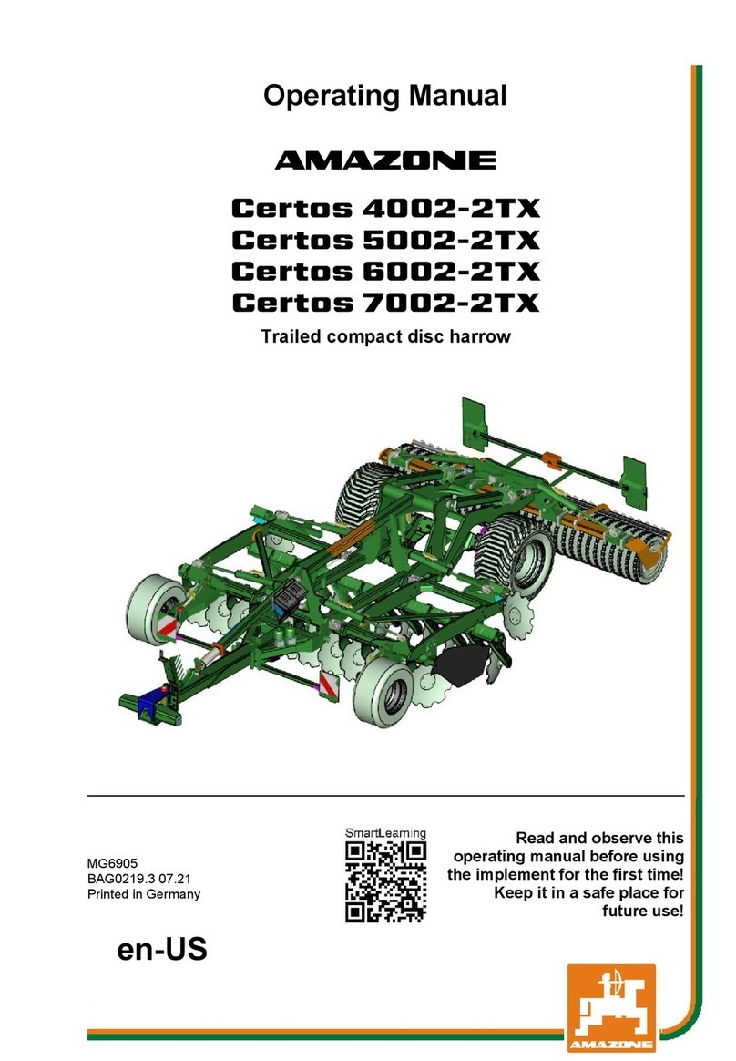
Amazone CatrosXL 4003-2TS User manual

Amazone

Amazone CatrosXL 4003-2TS User manual

Amazone Tyrok 400 Installation instructions

Amazone

Amazone Tyrok 400 Installation instructions

Amazone UX 6201 Super User manual

Amazone

Amazone UX 6201 Super User manual

Amazone Centaur 6001 Installation guide

Amazone

Amazone Centaur 6001 Installation guide

Amazone Cenius 4003-2TX User manual

Amazone

Amazone Cenius 4003-2TX User manual

Amazone Citan 12001-C User manual

Amazone

Amazone Citan 12001-C User manual

Amazone AD-P 03 SPECIAL User manual

Amazone

Amazone AD-P 03 SPECIAL User manual

Amazone AmaSpread 2 User manual

Amazone

Amazone AmaSpread 2 User manual

Amazone CATROS 7501-2T User manual

Amazone

Amazone CATROS 7501-2T User manual

Amazone AD-P 3001 Special 850 User manual

Amazone

Amazone AD-P 3001 Special 850 User manual

Amazone Catros 12003-2TS User manual

Amazone

Amazone Catros 12003-2TS User manual

Amazone UG 2200 Super User manual

Amazone

Amazone UG 2200 Super User manual

Amazone GHD 1500 User manual

Amazone

Amazone GHD 1500 User manual

Amazone Cataya User manual

Amazone

Amazone Cataya User manual

Amazone Cayena 6001 User manual

Amazone

Amazone Cayena 6001 User manual

Amazone ZA-X Perfect 02 User manual

Amazone

Amazone ZA-X Perfect 02 User manual

Amazone AW 6600 User manual

Amazone

Amazone AW 6600 User manual

Amazone Catros 4003-2 Installation instructions

Amazone

Amazone Catros 4003-2 Installation instructions

Amazone KG Special Series User manual

Amazone

Amazone KG Special Series User manual

Popular Farm Equipment manuals by other brands

Yetter 8500 SERIES owner's manual

Yetter

Yetter 8500 SERIES owner's manual

Monosem NG Plus 4 user manual

Monosem

Monosem NG Plus 4 user manual

UNIA MX user guide

UNIA

UNIA MX user guide

AGCO Challenger RoGator 600C Workshop service manual

AGCO

AGCO Challenger RoGator 600C Workshop service manual

Oypla GARDEN 4039 user manual

Oypla GARDEN

Oypla GARDEN 4039 user manual

LAUMETRIS MKL user manual

LAUMETRIS

LAUMETRIS MKL user manual

KIRLOSKAR KMW Univator Operator's and service manual

KIRLOSKAR

KIRLOSKAR KMW Univator Operator's and service manual

Dhollandia DH-RPL 22 installation manual

Dhollandia

Dhollandia DH-RPL 22 installation manual

aivituvin AIR 53 instruction manual

aivituvin

aivituvin AIR 53 instruction manual

Jay-Lor 2425 Operator's manual

Jay-Lor

Jay-Lor 2425 Operator's manual

Dion F63 installation instructions

Dion

Dion F63 installation instructions

GREAT PLAINS Terra Max HT1100-20 FIELD ADJUSTMENT GUIDE

GREAT PLAINS

GREAT PLAINS Terra Max HT1100-20 FIELD ADJUSTMENT GUIDE

Rauch AXIS-M 20.2 EMC instruction manual

Rauch

Rauch AXIS-M 20.2 EMC instruction manual

Fast DP9D owner's manual

Fast

Fast DP9D owner's manual

horsch Pronto 7 DC operating instructions

horsch

horsch Pronto 7 DC operating instructions

Brillion SOIL BUILDER II Operator's manual

Brillion

Brillion SOIL BUILDER II Operator's manual

Chore-Time REVOLUTION Installation and operator's manual

Chore-Time

Chore-Time REVOLUTION Installation and operator's manual

Gaspardo VITTORIA 250 Use and maintenance

Gaspardo

Gaspardo VITTORIA 250 Use and maintenance

manuals.online logo
manuals.online logoBrands
  • About & Mission
  • Contact us
  • Privacy Policy
  • Terms and Conditions

Copyright 2025 Manuals.Online. All Rights Reserved.