Lippert Solera Slider User manual

Rev: 06.16.2016 Page 1 Solera® Slider Install Manual
Solera® Slider
INSTALLATION MANUAL

Rev: 06.16.2016 Page 2 Solera® Slider Install Manual
System and Safety Information
System Information
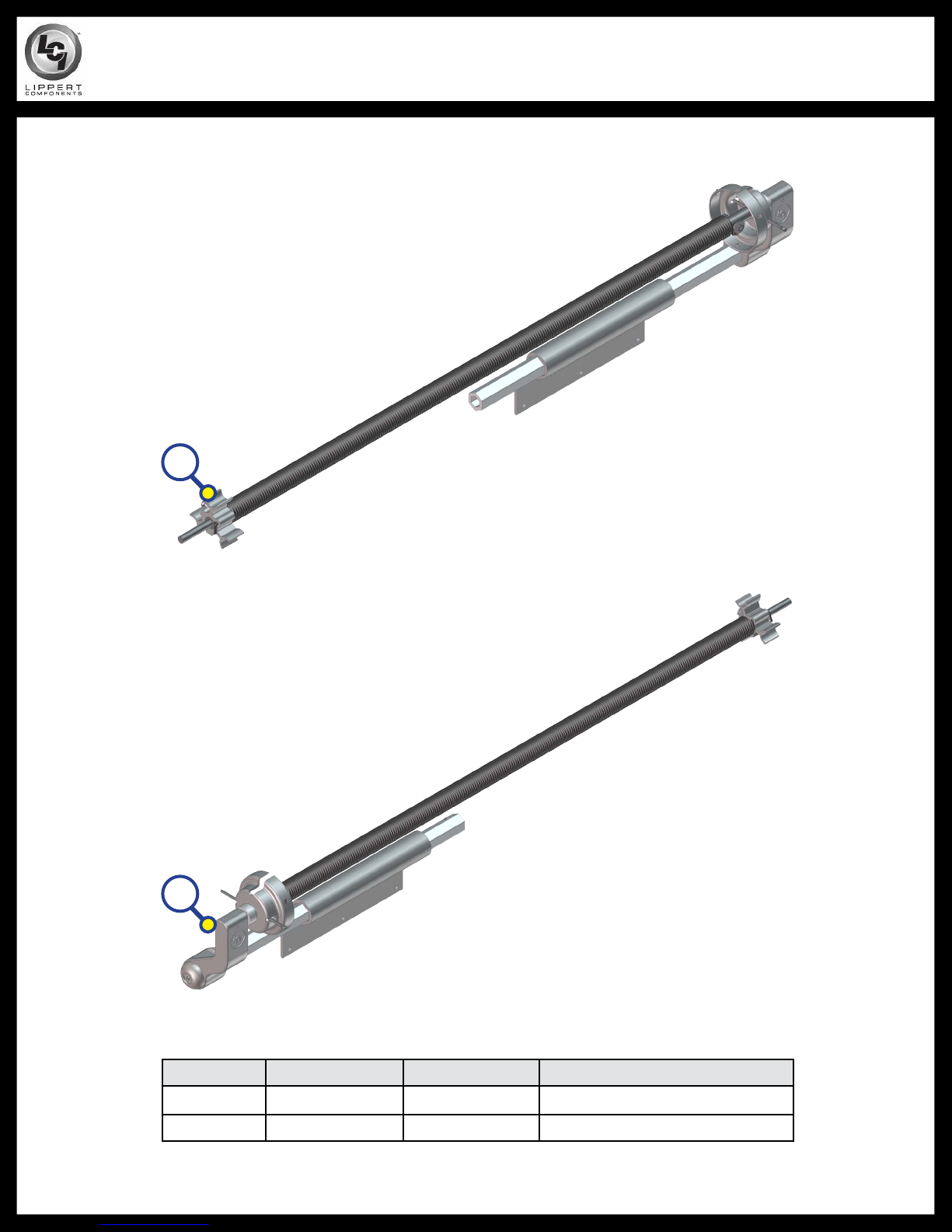
Solera Sliders are a high-quality, cost-effective way to help keep slide-outs free of dirt, leaves and debris. Solera
Sliders permanently attach to the slide-out and retract/extend with the room. The easy-to-install kits are designed
to fit rooms from 56" to 188" in length and extend up to 58”. The hardware hole pattern is universal and will match
most competitive brands, which alleviates the need to patch holes.
NOTES:
• The Solera Slider® kit comes complete with mounting hardware.
• Awning rail not included.
• All fabric is 5” shorter than the overall slider length.
• Box width is measured on the outside front of the box. Do NOT include T-molding.
Safety Information
This manual provides general installation procedures. Many variables can change the circumstances of the
procedure, i.e., the degree of difficulty involved in the service operation and the ability level of the individual
performing the operation. This manual cannot begin to plot out procedures for every possibility, but will provide
the general instructions for effectively installing the system. In the event the skill level required is too advanced
or the procedure too difficult, a certified technician should be consulted before performing the necessary service.
Failure to correctly install the system may result in voiding the warranty, inflicting injury or even death.
TABLE OF CONTENTS
System and Safety Information 2
System Information 2
Safety Information 2
Prior to Installation 3
Tools Required 3
Resources Required 3
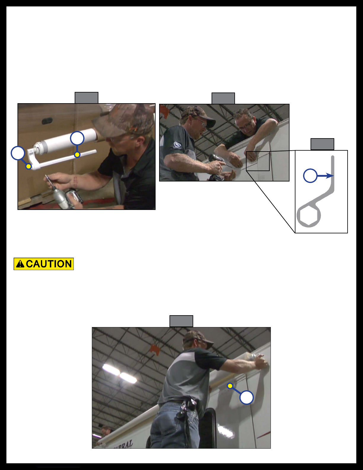
Installation 3
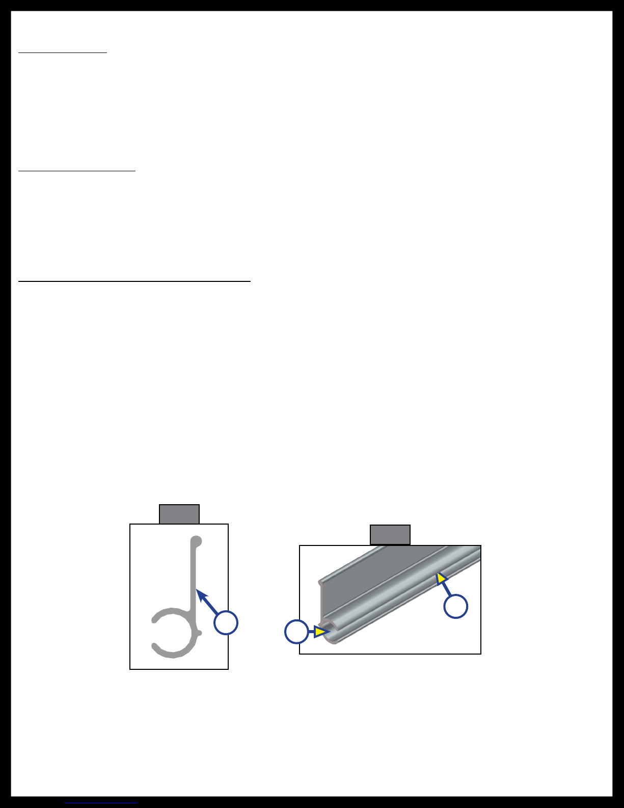
Installing the Awning Rail (If Necessary) 3
Installation 4
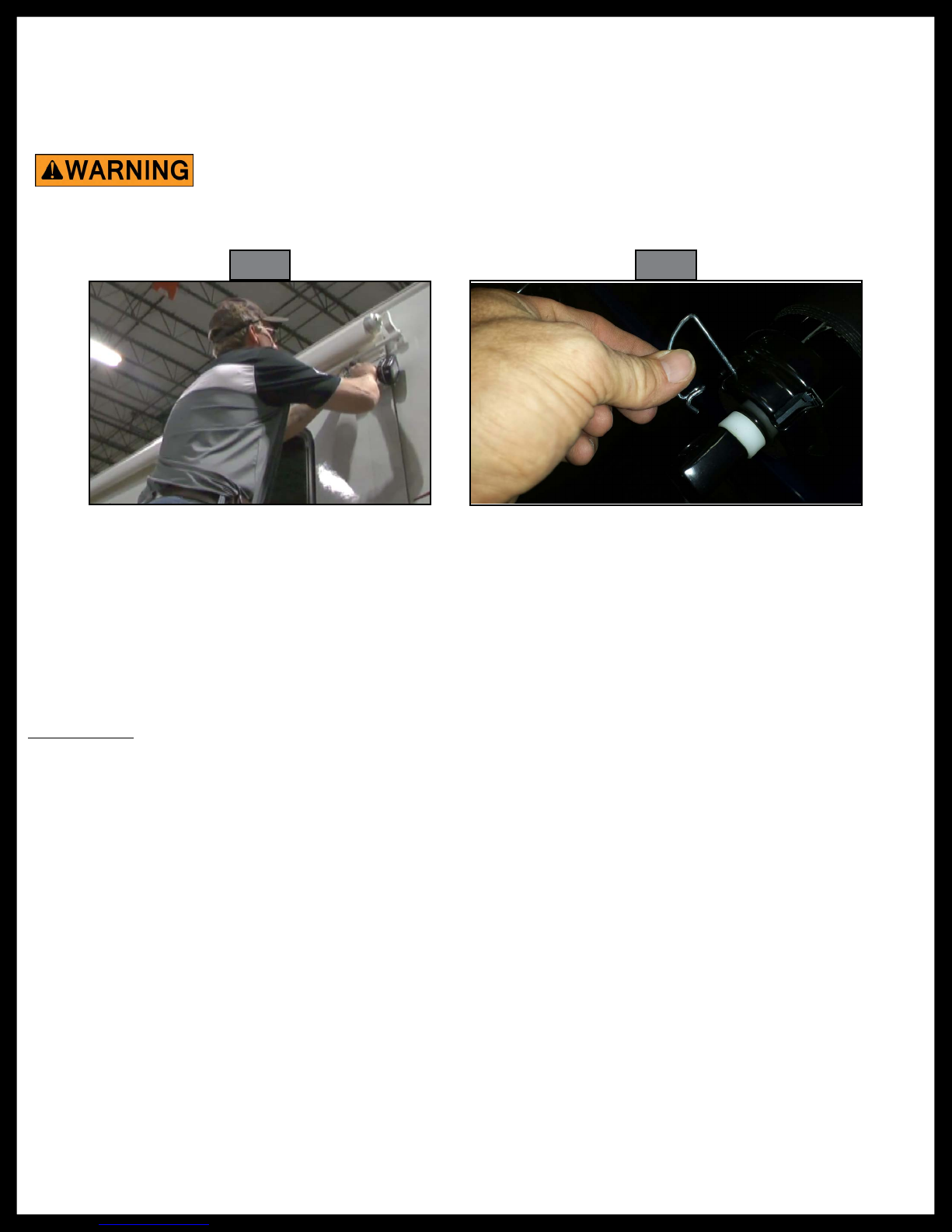
Failure to follow the instructions provided in this manual may result in death,
serious injury, vehicle damage, or voiding of the component warranty.
Always wear eye protection when performing service or maintenance to the
vehicle. Other safety equipment to consider would be hearing protection,
gloves and possibly a full face shield, depending on the nature of the service.
Moving parts can pinch, crush or cut. Keep clear and use caution.

Rev: 06.16.2016 Page 3 Solera® Slider Install Manual
Installation
NOTE: All screws/rivets supporting the awning assembly MUST have a backer within the structure of the
wall of the coach. Refer to coach manufacturer for proper location.
Installing the Awning Rail (If Necessary)
1. Position the awning rail along the line where roof and wall meet or a minimum of 6" above the upper
edge of the slide room the Solera® Slider is covering. Awning rail must be level and parallel with the
floor line of the coach.
2. After determining its proper location, mark its position with a non-permanent method of marking.
3. Seal the back of the awning rail (Fig. 1A) with putty tape or silicone sealant.
4. Align the awning rail on the wall and secure with #10 x ¾” screws, using all fastener holes.
5. Use a screwdriver to spread open either end of the awning rail on the installation side (Fig. 2A).
6. To protect the fabric from damage during installation, file any sharp edges or burrs from the awning
rail.
7. Use silicone lubricant and spray the inside of the awning rail track (Fig. 2B).
NOTE: Awning rail not included.
Prior to Installation
Tools Required
• Cordless or power screw gun
• ⁄" socket
• Square drill bit
• Butyl tape
• Tape measure
Resources Required
• Two People
Fig. 1
Fig. 2
A
B
A

Rev: 06.16.2016 Page 4 Solera® Slider Install Manual
13. Remove paper wrap from roll bar and bring fabric out one roll.
Unrolling fabric more than one roll will make the slider lose tension and create slack
when closing the slide. Make sure to leave the slide room closed or not to extend
more than 6”.
14. Using at least two people, feed the fabric through the awning rail (Fig. 6).
15. Feed one of the hex rods into the bracket. By pulling the hex rod all the way into the bracket, the other
hex rod will slide into the bracket at the opposite end (Fig. 6A).
Fig. 6
A
Fig. 3 Fig. 4
Fig. 5
8. Slide hex rod into roll bar arm and align the screw holes (Fig. 3A).
9. Slide end cap into other end of roll bar arm and align all three screw holes. Fasten using self-tapping
screws (Fig. 3B).
10. Apply butyl tape to bracket screw holes so that the butyl tape is against the coach when mounting
bracket (Fig. 5A).
11. Place bracket against the bottom of the T-molding at the top corner of the slide-out. Make sure to keep
the bracket parallel with the awning rail/T-molding. Fasten using self-tapping screws (Fig. 4).
12. Leave one of the hex bars free floating. Repeat Step 8-11 for other side.
B
A
A

Rev: 06.16.2016 Page 5 Solera® Slider Install Manual
16. Secure the second hex rod to the roller bar assembly.
17. Center the Solera® Slider over the slide room using a tape measure.
18. Fasten the hex rods to the brackets using two ⁄" hex head screws in each bracket (Fig. 7).
19. Grasp the roll bar to relieve tension and remove the spring clip (Fig. 8).
20. Test slider by extending and retracting the slide-out, being sure to watch the fabric.
Fig. 7 Fig. 8
Release the roll bar slowly to avoid damage to the assembly and serious injury.
Maintenance
Fabric Care
If the slider is rolled up while wet, roll it out and let it dry as soon as conditions allow before rolling it up
again. This will help prevent the formation of mildew and add greatly to the life of the slider. Mildew does
not form on the fabric itself, but on the accumulated dust, dirt and grime.
NOTE: Periodically clean vinyl or woven acrylic fabric using a mixture of ¼ cup of dish soap and 5 gallons of
warm water. Liberally apply the mixture on the top of the fabric and roll up the slider for 5 minutes.
This will apply the mixture to the bottom of the fabric as well. Roll the slider back out and hose off
with fresh water. Repeat if necessary. Allow to dry before rolling up.
Securing the Fabric
1. Roll the awning in and out several times to ensure that the fabric is square on the roll tube.
2. Secure the fabric in the awning rail by installing a #6 x 3/8” hex head screw through the fabric cord and
fabric 1” inside the edge of the fabric on both sides.

Rev: 06.16.2016 Page 6 Solera® Slider Install Manual
SOLERA® SLIDER ASSEMBLIES
A. Complete Solera® Sliders include fabric, roll bar, drive head assembly and idler head assembly.
B. Length of Solera® Sliders is measured from center of torsion bar to center of torsion bar and
hardware can be adjusted to fit multiple widths.
C. Label with variant code will be on the fabric in the corner.
Used On Box
Width
Solera®
Slider
Length
White Variant
Code
Black Variant
Code
56" to 61 ¾" 66" V000163273 V000168104
62" to 67 ¾" 72" V000163274 V000231482
68" to 73 ¾" 78" V000163279 V000165063
74" to 79 ¾" 84" V000163285 V000168105
80" to 85 ¾" 90" V000163287 V000165062
86" to 91 ¾" 96" V000163288 V000168106
92" to 97 ¾" 102" V000163289 V000168107
98" to 103 ¾" 108" V000163290 V000168108
104" to 109 ¾" 114" V000163291 V000168325
110" to 115 ¾" 120" V000163292 V000251461
116" to 121 ¾" 126" V000163293 V000182037
128" V000184672
122" to 127 ¾" 132" V000163294 V000168326
128" to 133 ¾" 138" V000163295 V000184673
140" V000168319 V000168327
141" V000177333
134" to 139 ¾" 144" V000139496 V000168328
140" to 145 ¾" 150" V000163298 V000177334
151" V000181971
154" V000168320 V000168329
146" to 151 ¾" 156" V000163299 V000165061
159" V000182454
152" to 157 ¾" 162" V000163300 V000168109
163" V000181970
165" V000168321
158" to 163 ¾" 168" V000163301 V000168110
164" to 169 ¾" 174" V000163302 V000168112
170" to 175 ¾" 180" V000163303 V000251477
176" to 181 ¾" 186" V000163304 V000251478
182" to 187 ¾" 192" V000163307 V000194925
198" V000163308

Rev: 06.16.2016 Page 7 Solera® Slider Install Manual
SOLERA® SLIDERS FABRIC ONLY
A. All Solera® Slider fabric produced prior to August 2014 will have a projection of 58". All fabric
produced after that date will have a projection of 50".
B. All fabric will be 5" shorter than the Solera® Slider length on order.
Used On Box
Width
Solera®
Slider
Length
White Variant
Code
Black Variant
Code
56" to 61 ¾" 66" V000253379 V000253350
62" to 67 ¾" 72" V000253380 V000253352
68" to 73 ¾" 78" V000253381 V000253353
83" V000260051
74" to 79 ¾" 84" V000253382 V000253354
88" V000260049
80" to 85 ¾" 90" V000253383 V000253355
86" to 91 ¾" 96" V000253384 V000253356
92" to 97 ¾" 102" V000253385 V000253357
98" to 103 ¾" 108" V000253386 V000253358
104" to 109 ¾" 114" V000253387 V000253359
110" to 115 ¾" 120" V000253388 V000253360
116" to 121 ¾" 126" V000253389 V000253362
122" to 127 ¾" 132" V000253390 V000253361
128" to 133 ¾" 138" V000253391 V000253367
134" to 139 ¾" 144" V000253392 V000253369
140" to 145 ¾" 150" V000253393 V000253370
154" V000279899
146" to 151 ¾" 156" V000253394 V000253371
160" V000224582
152" to 157 ¾" 162" V000253397 V000253372
158" to 163 ¾" 168" V000253398 V000253373
164" to 169 ¾" 174" V000253399 V000253374
170" to 175 ¾" 180" V000253401 V000253375
176" to 181 ¾" 186" V000253402 V000253376
182" to 187 ¾" 192" V000253403 V000253377

Rev: 06.16.2016 Page 8 Solera® Slider Install Manual
SOLERA® SLIDER HEAD ASSEMBLIES
A
B
Callout White Part # Black Part # Description
A 272455 285149 Drive Head Assembly
B 272454 285148 Idler Head Assembly

Rev: 06.16.2016 Page 9 Solera® Slider Install Manual
SOLERA® SLIDER COMPONENTS
C
D
E
F
G
Variant Code Information
The variant code on Lippert products can assist LCI customers in obtaining additional information about the
product and its components. On the Solera® Slider, the label will be located on the fabric portion of the assembly.
For replacement part information, locate the variant code as outlined below and call LCI customer service at 574-
537-8900.
Variant Code
Callout White Part # Black Part # Description
NOTE: The following are the only parts of the heads that may be ordered separately:
C 2724391 2724392 Extension Rod
D 2724411 2724412 Extension Bracket
E 2724561 2724562 Torsion Arm Cap
F 300247 Screw #10 - 16 x ¾ hwh zn hex
G 300234 Screw #10 - 13 x 1 ¼ csk zn sqd

The contents of this manual are proprietary and copyright protected by Lippert Components, Inc. (“LCI”).
LCI prohibits the copying or dissemination of portions of this manual unless prior written consent from an
authorized LCI representative has been provided. Any unauthorized use shall void any applicable warranty.
The information contained in this manual is subject to change without notice and at the sole discretion of LCI.
Revised editions are available for free download from www.lci1.com.
Please recycle all obsolete materials.
For all concerns or questions, please contact
Lippert Components, Inc.
Rev: 06.16.2016 Page 10 Solera® Slider Install Manual
Table of contents
Other Lippert Accessories manuals

Lippert
Lippert Solera 5000 Series User manual

Lippert
Lippert Solera Classic Awning Use and care manual

Lippert
Lippert Solera Classic Awning Installation instructions

Lippert
Lippert SureShade Power Bimini Instruction Manual

Lippert
Lippert 2021130655 Installation instructions

Lippert
Lippert Solera Power Installation instructions

Lippert
Lippert Solera Power User manual

Lippert
Lippert Solera 5000 Series Installation instructions

Lippert
Lippert Solera 5000 Series User manual

Lippert
Lippert Solera Classic User manual