Lippert Solera Classic Awning Installation instructions

1
lci1.com 574-537-8900 Rev: 07.27.21
Solera®Classic
Awning (AU)
Installation and Owner’s Manual
(For Aftermarket Applications)
CCD-0001254-AU
BY
Table of Contents
Introduction ............................................ 2
Quick Facts ............................................ 2
Safety ................................................... 2
Preparation ............................................. 3
Resources Required ................................... 3
Classic Awnings Pre-Install Turn Chart ................ 3
Installation .............................................. 3
Installing the Awning Rail (If Needed) ................. 3
Assembling the Awning ................................ 4
Installing the Bottom Mounting Brackets ............... 5
Mounting the Awning .................................. 5
Securing the Fabric .................................... 8
Installing the Stop Bolt ................................. 8
Operation ............................................... 9
Extending the Awning ................................. 9
Extending Optional Car Port ......................... 11
Retracting the Awning ............................... 11
Solera®Classic
Awning (AU)
Installation and
Owner’s Manual
(For Aftermarket Applications)
Troubleshooting ...................................... 13
Maintenance .......................................... 15
Resources Required ................................. 15
Fabric Care .......................................... 15
Notes .................................................. 15

2
lci1.com 574-537-8900 Rev: 07.27.21
Solera®Classic
Awning (AU)
Installation and Owner’s Manual
(For Aftermarket Applications)
CCD-0001254-AU
Introduction
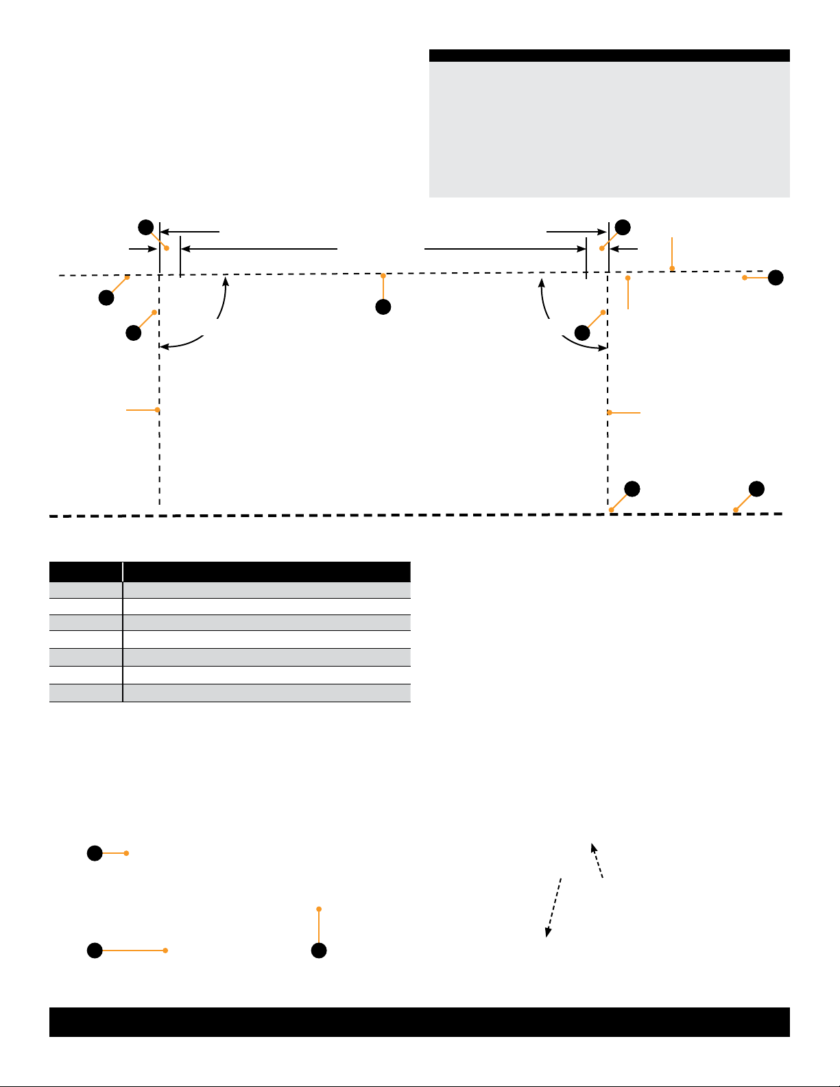
The rugged spring-loaded Solera®Classic extends and
retracts in just a few easy steps. Simply release the travel
locks on each arm, loosen the rafter knobs, use the pull
cane to unlock the roller, then hook the pull strap and walk
it out to unroll the awning. Once extended, set the tension,
tighten rafter knobs and raise the awning arms to whatever
pitch you want for shade and water runoff. You can also
detach the arms from the bottom bracket and rotate them
to a vertical “carport” position. This carport position makes
it easy to attach Solera accessories like the Screen Room
and Solera Family Room™.
Quick Facts
• Standard 8’ projection
• Classic brackets align perfectly with bracket holes of
most brands of manual awnings
• Arms detach from bottom bracket and easily swing to
“carport” position
NOTE: Images used in this document are for reference
only when assembling, installing and/or operating this
product. Actual appearance of provided and/or purchased
parts and assemblies may differ.
Additional information about this product can be obtained
from lci1.com/support or by using the LippertNOW app.
The LippertNOW app is available for free on Apple App
Store®for iPhone®and iPad®and also on Google Play™for
Android™users.
App Store®, iPhone®, and iPad®are registered trademarks
of Apple Inc.
Google Play™and Android™are trademarks of Google Inc.
Information regarding the assembly and components of
this product can be obtained from https://support.lci1.com/
solera-classic-awning .
Safety
Read and fully understand all instructions before installing
or operating this product. Adhere to all safety labels.
This manual provides general instructions. Many variables
can change the circumstances of the instructions, i.e., the
degree of difficulty, operation and ability of the individual
performing the instructions. This manual cannot begin
to plot out instructions for every possibility, but provides
the general instructions, as necessary, for effectively
interfacing with the device, product or system. Failure
to correctly follow the provided instructions may result
in death, serious personal injury, severe product and/
or property damage, including voiding of the LCI limited
warranty.
THE “WARNING” SYMBOL ABOVE IS A SIGN THAT
A SAFETY RISK IS INVOLVED AND MAY CAUSE
DEATH, SERIOUS PERSONAL INJURY AND/OR
SEVERE PRODUCT OR PROPERTY DAMAGE IF
NOT SAFELY ADHERED TO AND WITHIN THE
PARAMETERS SET FORTH IN THIS MANUAL.
FAILURE TO FOLLOW THE INSTRUCTIONS
PROVIDED IN THIS MANUAL MAY RESULT IN DEATH,
SERIOUS INJURY, PROPERTY DAMAGE, OR VOIDING
OF THE COMPONENT WARRANTY.
REMOVING FABRIC TAPE OR SPRING ASSEMBLY
COTTER PINS PREMATURELY COULD CAUSE
SERIOUS INJURY OR PROPERTY DAMAGE.
THE “CAUTION” SYMBOL ABOVE IS A SIGN THAT
A SAFETY RISK IS INVOLVED AND MAY CAUSE
PERSONAL INJURY AND/OR PRODUCT OR
PROPERTY DAMAGE IF NOT SAFELY ADHERED
TO AND WITHIN THE PARAMETERS SET FORTH
IN THIS MANUAL.

3
lci1.com 574-537-8900 Rev: 07.27.21
Solera®Classic
Awning (AU)
Installation and Owner’s Manual
(For Aftermarket Applications)
CCD-0001254-AU
Installation
NOTE: All screws supporting the awning assembly MUST
have a backer within the structure of the wall of the unit.
Refer to the unit manufacturer for proper location.
Installing the Awning Rail (If Needed)
NOTE: Awning rail not included.
1. Installation of awning rail is dependent on sidewall
mounting or pop top mounting.
A. Sidewall Mounting -
Position the awning rail along the
line where roof and wall meet, or a minimum of 4" above
doors or windows (Fig.1).
B. Pop Top Mounting - Position the awning rail above
the line where roof and wall meet (Fig.1).
NOTE: The awning rail must be level and parallel with the
floor line of the unit (Fig.1).
2. After determining the awning rail's proper location, mark
its position with a non-permanent method of marking.
3. Seal the back of the awning rail.
4. Secure the awning rail:
A. Sidewall Mounting - Align the awning rail on the wall
and secure with #10 x ¾” screws, using all fastener holes.
B. Pop Top Mounting - Align the awning rail on the roof
and secure with #10 x ¾” screws, using all fastener holes.
MOVING PARTS CAN PINCH, CRUSH OR CUT. KEEP
CLEAR AND USE CAUTION.
NOTE: Solera®Classic Awning drive and idler heads
are preloaded with tension and secured with cotter pins
from the factory. If the cotter pins have been removed
or otherwise lost, and tension needs to be added to the
heads, use the “Classic Awnings Pre-install Turn Chart” to
add the correct number of turns to the awning heads.
A. Turn the drive head clockwise the correct number of
turns.
B. Turn the idler head counterclockwise the correct
number of turns.
C. For both A and B, insert a cotter pin into the end
cap into the shaft on both the drive and idler side head
assemblies after adding tension.
NOTE: If awning is on a work surface, base the direction of
the turns (clockwise or counterclockwise) on the orientation
of the awning assembly on the unit..
Roll Tube WidthRoll Tube Width Turns
6' to 14' 4
15' 5
16' to 18' 6
19' to 21' 8
• 1 to 3 people
• Cordless or electric drill or
screw gun
• Appropriate drive bits,
including 3/8” and ½”
• Screwdriver
• Ratchet
• 7/16” Socket
• ½” Socket
• ½” Wrench
• 3/16” Drill bit
• Non-permanent method
of marking
• Silicone sealant or
butyl tape
• Silicone lubricant
• #10 x ¾” self-tapping
screws
• ¼” - 20 x ½” Hex head
Screws
• ¼” x 2 ½” Lag screws
• #6 x ½” hex head
self-tapping screws
Preparation
Classic Awnings Pre-Install Turn Chart
Do NOT remove the following items until instructed:
1. Tape securing the fabric
2. Cotter pins in the spring assemblies
Resources Required

4
lci1.com 574-537-8900 Rev: 07.27.21
Solera®Classic
Awning (AU)
Installation and Owner’s Manual
(For Aftermarket Applications)
CCD-0001254-AU
side view
dotted line
= vertical
centerline
dotted line
= vertical
centerline
Awning Rail Assembly Parts
floor line
front facing view
A
B
C
B
DD
E
Fig.1
Callout Description
AAwning Rail
B Support Arm
C Roll Tube Assembly
DLower Mounting Bracket
EUpper Mounting Bracket
F Approximately 5" from Center Line to Fabric
G Approximately 5" from Center Line to Fabric
90°
Assembling the Awning
NOTE: The head assemblies (Fig.2A) and support arm
assemblies (Fig.2B) are no longer numbered.
Fig.2
A
1. On a at surface, carefully lay out the support arm
assemblies and roll tube assembly. The cam lock (Fig.2C)
MUST be on the left end of the roll tube when facing
the unit.
NOTE: Take care not to set the awning on any surface that
may damage the assembly or fabric.
2. Slide the right support arm assembly into the idler head
assembly of the roll tube. Align the holes and secure using
one ¼" - 20 x ½” hex head screw.
3. Repeat step 2 for the left support arm assembly (Fig.3).
B C
Fig.3
90°
awning width = bolthead-to-bolthead in 12" increments
roof/wall
line
fabric width
awning
rail
F G

5
lci1.com 574-537-8900 Rev: 07.27.21
Solera®Classic
Awning (AU)
Installation and Owner’s Manual
(For Aftermarket Applications)
CCD-0001254-AU
Installing the Bottom Mounting Brackets
1. On the awning rail, mark the position of the centerlines
of the support arm assemblies. Make sure that the support
arm assemblies will not interfere with any lights, vents or
the operation of any windows or doors.
2. Using a non-permanent method of marking, mark a
perpendicular line from the mark on the awning rail down
to the oor line. This is the centerline of the support arm
assembly (Fig.1). Do this for both support arm assemblies.
3. Position the bottom bracket with the fastening points
at the oor line (Fig.4A).
A. Center the bracket on the centerline mark of the
support arm assembly (Fig.4B).
B. Mark the hole locations, then using a 3/16” drill bit,
pre-drill both holes.
C. Apply a liberal amount of sealant over the holes.
D. Attach the bracket using the provided ¼” x 2 ½”
lag screws (Fig.4C).
A
Fig.4
Mounting the Awning
1. Measure the distance from the awning rail channel to the
lower mounting bracket fastening point.
2. Compare the distance from the center of the roll tube
and the support arm assembly foot to the measurement in
step 1 and adjust the support arm assembly to make both
distances equal.
A. Open the support arm assembly handle (Fig.5) and
slide the outer arm lower channel #2 (Fig.6) up or down
to desired height.
B. Close the handle and slide the outer arm lower
channel #2 (Fig.6) until the locking pin clicks into the
nearest positioning hole.
Fig.5
support arm
assembly
handle
4. Measure and conrm the width of the awning. The
distance is measured from centerline of support arm
assembly to the opposite centerline of the other support
arm assembly (Fig.1).
NOTE: All screws supporting the awning assembly MUST
have a backer within the structure of the wall of the unit.
Refer to unit’s manufacturer for proper backer location.
4. Repeat step 3 for the other end of the awning.
B
C

6
lci1.com 574-537-8900 Rev: 07.27.21
Solera®Classic
Awning (AU)
Installation and Owner’s Manual
(For Aftermarket Applications)
CCD-0001254-AU
3. Use a screwdriver to spread open either end of the
awning rail on the installation side (Fig.7A).
4. To protect the fabric from damage during installation, le
any sharp edges or burrs from the awning rail channel.
5. Spray the inside of the awning rail channel (Fig.7B) with
silicone lubricant.
6. Remove the packaging from the fabric. Unroll a small
portion of fabric, but not more than one rotation of fabric.
NOTE: The next step will require three people: one to feed
the polycord into the awning rail channel; two to walk the
support arm assemblies along the awning rail while the
fabric slides into position.
7. Slide the polycord into the awning rail channel and walk
the support arm assemblies and fabric down the awning
rail channel until the support arm assemblies are in line
with the centerline marks made previously.
Fig.6
channel #1
channel #2
channel #3
channel #4
locking knob
8. Lift the support arm assembly up and secure the feet
into the previously installed bottom mounting brackets
by pressing the lever and opening the latch (Fig.8).
9. Slide the support arm upper channel #3 (Fig.6)
up or down as needed over the support arm lower
channel #4 (Fig.6).
NOTE: If adjustments need made so the upper mounting
brackets straddle the awning rail, loosen the black locking
knob on the support arm upper channel #3 (Fig.6).
Fig.7
Fig.8
push to open
A
B

7
lci1.com 574-537-8900 Rev: 07.27.21
Solera®Classic
Awning (AU)
Installation and Owner’s Manual
(For Aftermarket Applications)
CCD-0001254-AU
10. Secure the upper mounting bracket.
A. Sidewall - Center the upper mounting brackets on
the support arm assembly centerline marked previously
and arrange the upper mounting brackets to straddle the
awning rail (Fig.9). Tighten the black locking knob on the
mount/rafter arm upper channel (channel #3) (Fig.6).
B. Pop Top - Center the upper mounting brackets on the
support arm assembly centerline marked previously and
arrange the upper mounting brackets on the wall of the
unit below the line where the roof (Pop Top) and wall meet
(Fig.10). Tighten the black locking knob on the mount/rafter
arm upper channel (channel #3) (Fig. 6).
11. Once the upper bracket is situated, mark and
pre-drill two 3/16” holes through the awning rail or unit.
Apply a liberal amount of sealant over the holes and attach
the upper mounting bracket using the ¼” x 3” lag screws or
equivalent (not provided) (Figs.9 and 10).
NOTE: All screws supporting the awning assembly MUST
have a backer within the structure of the wall of the unit.
Refer to the unit manufacturer for proper location. It is
acceptable that the lag screws go through the flat portion
of the awning rail.
Upper Mounting Bracket
Fig.9
Lag Screws Awning Rail
Fig.10
Sidewall Installation Pop Top Installation
12. Repeat steps 8-11 for the other support arm assembly.
13. Place cam lock into the roll-out position. Firmly grasp
the roll tube and remove the safety cotter pin from each
end of the roll tube.
FAILURE TO MAINTAIN CONTROL OF THE ROLL
TUBE, FABRIC AND SUPPORT ARM ASSEMBLIES
MAY RESULT IN SERIOUS PERSONAL INJURY OR
PROPERTY DAMAGE.
USE CARE WHEN REMOVING THE COTTER PINS.
THE COTTER PINS ARE HOLDING THE PRE-WOUND
TENSION OF THE SPRING. FAILURE TO SECURELY
HOLD THE ROLL TUBE MAY ALLOW THE ROLL
TUBE TO RAPIDLY ROLL UP AND CAUSE PERSONAL
INJURY OR PROPERTY DAMAGE.
14. Firmly grasp and hold the pull strap. While maintaining
control of the awning with the pull strap, place cam lock into
the roll-in position and allow the fabric to slowly roll up.

8
lci1.com 574-537-8900 Rev: 07.27.21
Solera®Classic
Awning (AU)
Installation and Owner’s Manual
(For Aftermarket Applications)
CCD-0001254-AU
Fig.11
awning rail 1”
A
Installing the Stop Bolt
1. Make sure the awning is completely retracted.
2. Make sure the roll tube centerline is level with or slightly
higher than the awning rail centerline (Fig.1). The bottom of
the roll tube MUST not be higher than the awning rail.
3. Adjust support arm assemblies if necessary.
A. Open the outer arm handle (Fig.12) and slide the
outer arm upper channel #1 (Fig.6) up or down to the
desired height.
support arm
assembly
handle
Fig.12
B. Close the handle and slide the outer arm upper
channel #1 (Fig.6) upward on the outer arm lower channel
#2 (Fig.6) until the locking pin clicks into the nearest
positioning hole.
4. With a non-permanent method of marking, mark the
position of the stop hole that is directly below the outer
arm upper channel #1 (Fig.6).
5. From the inside of the outer arm lower channel #2 (Fig.6),
insert a 5/16” bolt through the hole. Secure with a
star washer and a 5/16” acorn nut using ½” socket and
wrench (Fig.13).
NOTE: It may be necessary to lift the outer arm upper
channel #1 (Fig.6) to tighten the acorn nut.
6. Repeat steps 3-5 for the other support arm.
Fig.13
star
washer
acorn nut
bolt
Securing the Fabric
1. Roll the awning in and out several times to ensure that
the fabric is square on the roll tube.
2. Secure the fabric in the awning rail no more than 1”
inside the edge of the fabric on both ends using a #6 x
½” hex head self-tapping screw. Install the screw into the
awning rail into the fabric and the polycord (Fig.11).

9
lci1.com 574-537-8900 Rev: 07.27.21
Solera®Classic
Awning (AU)
Installation and Owner’s Manual
(For Aftermarket Applications)
CCD-0001254-AU
Fig.14
Operation
A
B
C
D
C
DA
Fig.15
Extending the Awning
1. Release the travel locks accordingly as they appear on
the unit.
A. Current Travel Lock - Press slightly upward on the tab
(Fig.14A) on the travel lock base latch (Fig.14B) to release
the travel lock body (Fig.14C). Swing the travel lock body
arm (Fig.14D) from behind the support bracket (Fig.15A) to
release the outer arm (Fig.15D).
Fig.16
A
B
C
E
D
PRIOR TO RAISING THE POP TOP ON A POP UP
TRAILER, THE CAM LOCK MUST BE IN THE ROLL
OUT POSITION. FAILURE TO DO SO CAN RESULT IN
DAMAGE TO THE TRAILER.
B
B. Original Travel Lock - Release the travel locks
(Fig.16B) on the support arm brackets by reaching behind
the support bracket (Fig.16A) and squeezing the travel lock
sides inward, releasing the outer arm (Fig.16E).

10
lci1.com 574-537-8900 Rev: 07.27.21
Solera®Classic
Awning (AU)
Installation and Owner’s Manual
(For Aftermarket Applications)
CCD-0001254-AU
4. Using the pull rod, start pulling the awning outward until
full extension is complete.
2. Loosen the black locking knobs (Fig.17A) on the support
arms.
3. Flip the cam lock (Fig.18B) down to the roll out position.
Fig.17
B
Fig.18
C
A
A
B
Fig.19
A
5. Slide the bottom of the support arms (Fig.17B) all the way
to the top of the outer arm (Fig.17C) and make sure they lock
into place at the top of the outer arm (Fig.18A).
6. Pull on the outer arms to ensure the fabric is taut and
tighten the black locking knob (Fig.17A) to lock it into place.
B
C
7. Raise the outer arms to the desired height by releasing
the support arm assembly handle (Fig.19A) and allow the
outer arm upper channel (Fig. 19B) to slide on the outer arm
lower channel (Fig. 19C). After reaching the desired height
let go of the support arm assembly handle to lock the arm
at this position.
8. Slide the pull strap to one end or the other and wrap it
around the arm to get it out of the way.

11
lci1.com 574-537-8900 Rev: 07.27.21
Solera®Classic
Awning (AU)
Installation and Owner’s Manual
(For Aftermarket Applications)
CCD-0001254-AU
Extending Optional Car Port
1. After steps 1-8 in the Extending the Awning section
are complete, remove the outer arm (Fig.20A) from the
side of the unit by releasing the lever (Fig.20B) on the
lower mounting bracket (Fig.20C).
2. Walk the awning out until the outer arm is straight up
and down and let it set on the ground.
3. Make sure to secure the foot of the outer arm (Fig.20D)
to the ground with the provided stakes.
Retracting the Awning
NOTE: Do NOT retract the awning while in carport mode.
1. If the awning is in car port mode, remove the stakes
from the foot of the outer arm (Fig.20D). Walk the outer
arm back to the unit and secure it into the lower mounting
bracket on the sidewall by pushing the lever (Fig.20B) on
the lower mounting bracket (Fig.20C) and inserting the outer
arm pin (Fig.20E) into the lower mounting bracket of the unit.
Repeat procedure on other end.
2. Unwrap the awning pull strap and return it to the center
of the awning roll tube.
3. Lower the outer arms by releasing the outer arm
assembly handle (Fig.19A) and allow the outer arm upper
channel (Fig.19B) to slide down the outer arm lower
channel (Fig.19C) until it rests on the acorn nut. Repeat the
procedure for the other end.
A
B
C
D
Fig.20
4. Loosen the black locking knob (Fig.17A) and unlock the
support arm by releasing the spring clip (Fig.21A) at the top
of the outer arm head assembly. Allow the support arm to
slide all the way down toward the bottom of the outer arm.
Repeat this for both ends.
5. Take a rm hold on the awning strap and release the
tension on the springs by ipping the cam lock (Fig.22A) up
to the roll in position.
Fig.21
E
A
6. Walk the awning in toward the unit. Hook the pull rod
into the pull strap before the strap gets too high. Using
the pull rod, walk the awning to the fully-closed position.
Remove the hook from the pull strap and store in a secure
location.
A
Fig.22

12
lci1.com 574-537-8900 Rev: 07.27.21
Solera®Classic
Awning (AU)
Installation and Owner’s Manual
(For Aftermarket Applications)
CCD-0001254-AU
Fig.23
A
DC
B
7. Secure travel locks accordingly as they appear on the unit.
A. Current Travel Lock - Compress the outer arm and
support arm together. Swing the travel lock body (Fig.23A)
down onto the travel lock base latch (Fig.23B). The travel
lock body will catch the tab (Fig.23C) to close. The travel
lock body's arm (Fig.23D) will wrap behind the arms.
Tighten the black locking knob (Fig.24C).
Fig.24
A
B
C
E
D
A
B
C
D
Fig.25
B. Original Travel Lock - Lock the arms for travel mode
by compressing the outer arm and support arm together
until the outer arm (Fig.25E) clicks into the travel locks
(Fig.25B) on the support arm (Fig.25A). Tighten the black
locking knob (Fig.25C).

13
lci1.com 574-537-8900 Rev: 07.27.21
Solera®Classic
Awning (AU)
Installation and Owner’s Manual
(For Aftermarket Applications)
CCD-0001254-AU
What is happening?What is happening? Why?Why? What should be done?What should be done?
Awning will not extend.
Cam lock engaged. Check position of the cam lock (roll out).
Travel locks engaged. Make sure that the travel locks have been
released from the outer arm.
Rafter arm(s) locking knob(s) engaged. Make sure the locking knob for the rafters
has been loosened.
Outer arm(s) is not aligned properly.
Check to see if the outer arm is resting
on the mount/rafter arm. If so, the outer
arm height adjustment is not set properly.
Readjust outer arm height.
Awning will not retract or only
retracts part way.
Rafter arm(s) locking knob(s) is engaged.
Make sure the mount/rafter arms have been
put in the stored position and the locking
knob has not been tightened.
Cam lock not engaged. Check position of cam lock (roll in).
Outer arm(s) stored properly. Make sure the outer arms have been placed
in the closed/stored position.
Spring tension not engaged. Make sure the awning has the proper
tension on it.
Outer arm(s) is in secured position. Make sure that the mount/rafter arm is not
secured to the head of the outer arm.
Fabric is loose or sags on the
edges and middle.
Rafter arm(s) locking knob not engaged.
Make sure that the mount/rafter arm has
been pulled tight and the locking knob is
secured.
Fabric out of alignment. Check that the fabric is square on the unit
and with the roll tube.
Fabric is loose on awning rail. Make sure the fabric is properly secured to
the awning rail on the unit.
Roll tube has been damaged. Make sure roll tube is not bent.
Locking knob will not tighten. Locking knob assembly has been damaged.
The lock knob screws into the channel nut
and tightens the arms together. Open the
awning, check when turning the knob that
the nut is not stripped out. If it is stripped, it
will require replacing both parts.
Mount/rafter arm will not extend.
Rafter arm(s) locking knob(s) is engaged. Make sure the locking knob has been loosened.
Debris is lodged in track arm(s). Make sure there is no debris in the track the
arm slides in.
Arm(s) is damaged. Make sure arm is not bent.
Awning will not stay in the rolled
out position. Cam lock wear may be present.
Check the cam lock. Signs of a faulty cam
lock include:
• The absence of a clicking noise when
the awning is rolled out.
• The awning rolling back up after it is
placed in the stop position.
Troubleshooting
*Troubleshooting chart continued on next page.

14
lci1.com 574-537-8900 Rev: 07.27.21
Solera®Classic
Awning (AU)
Installation and Owner’s Manual
(For Aftermarket Applications)
CCD-0001254-AU
What is happening?What is happening? Why?Why? What should be done?What should be done?
Awning will not roll up straight.
Fabric out of alignment.
Check to make sure fabric is centered on
roll tube and also centered between the
arms attached to the unit.
Fabric has shifted within awning rail.
If the fabric is not centered, move the
screws on both ends of the awning and
shift the fabric accordingly.
Anchoring screws within awning rail are
missing.
Make sure there are screws at both ends
of the fabric securing it to the roll tube
and at the awning rail. If there is only one
screw at one end and not the other, the
awning may not roll up correctly. Install
missing second screw.
Arm(s) is damaged. Make sure the arms are square and straight.
Troubleshooting (continued)

15
lci1.com 574-537-8900 Rev: 07.27.21
Solera®Classic
Awning (AU)
Installation and Owner’s Manual
(For Aftermarket Applications)
CCD-0001254-AU
If the awning is retracted while wet, extend the awning
and let it dry as soon as conditions allow before retracting.
This will help prevent the formation of mildew and add
greatly to the life of the awning.
NOTE: Mildew does not form on the fabric itself, but on
the accumulated dust, dirt and grime.
Periodically clean vinyl or woven acrylic fabric using
a mixture of ¼cup of dish soap and five gallons of
warm water.
1. Liberally apply the mixture on the top of the fabric
and retract the awning for ve minutes. This will apply
the mixture to the bottom of the fabric as well.
2. Extend the awning and hose o with fresh water.
3. Repeat if necessary.
4. Allow awning to dry before retracting.
OVER-SPRAY OF CLEANING SOLUTION CAN CAUSE
EYE AND SENSITIVE SKIN IRRITATION. FLUSH
AFFECTED AREA WITH CLEAN WATER AND SEEK
MEDICAL ATTENTION, IF NECESSARY. WEAR EYE
PROTECTION AND APPROPRIATE PROTECTIVE
CLOTHING TO AVOID PERSONAL INJURY
MOVING PARTS CAN PINCH, CRUSH OR CUT. KEEP
CLEAR AND USE CAUTION.
Fabric Care
Maintenance
Resources Required
• 5 gallon bucket
• Clean water
• ¼cup of dish soap
• Bristle brush with
sufficient reach
Notes

16
lci1.com 574-537-8900 Rev: 07.27.21
Solera®Classic
Awning (AU)
Installation and Owner’s Manual
(For Aftermarket Applications)
CCD-0001254-AU
Manual information may be distributed as a complete
document only, unless Lippert Components provides
explicit consent to distribute individual parts.
All manual information is subject to change without
notice. Revised editions will be available for free
download at lci1.com. Manual information is considered
factual until made obsolete by a revised version.
Please recycle all obsolete materials and contact
Lippert Components with concerns or questions.
Notes
Other manuals for Solera Classic Awning
1
Table of contents
Other Lippert Accessories manuals

Lippert
Lippert Solera 5000 Series User manual

Lippert
Lippert Solera Slider User manual

Lippert
Lippert Solera Power User manual

Lippert
Lippert SureShade Power Bimini Instruction Manual

Lippert
Lippert Solera Classic Awning Use and care manual

Lippert
Lippert Solera Classic User manual

Lippert
Lippert Solera 5000 Series Installation instructions

Lippert
Lippert Solera Power Installation instructions

Lippert
Lippert 2021130655 Installation instructions

Lippert
Lippert Solera 5000 Series User manual