Mode
Hy1
Addr
Mode
Bitrate
001
Hy1
8
H8s
001
044
DMX Hz 044
Edit
Smooth
Bitrate
Curve
ON
8
STD
CCT
2600k 0%
Mstr
Smooth
Bitrate
Curve
ON
8
STD
Next
Smooth
Bitrate
Curve
ON
8
STD
Next
Smooth
Bitrate
Curve
ON
8
STD
Next
Edit
Mode
Hy1
Addr
Mode
Bitrate
001
Hy1
8
H8s
001
044
DMX Hz 044
Edit
Smooth
Bitrate
Curve
ON
8
STD
CCT
2600k 0%
Mstr
Smooth
Bitrate
Curve
ON
8
STD
Next
Smooth
Bitrate
Curve
ON
8
STD
Next
Smooth
Bitrate
Curve
ON
8
STD
Next
Edit
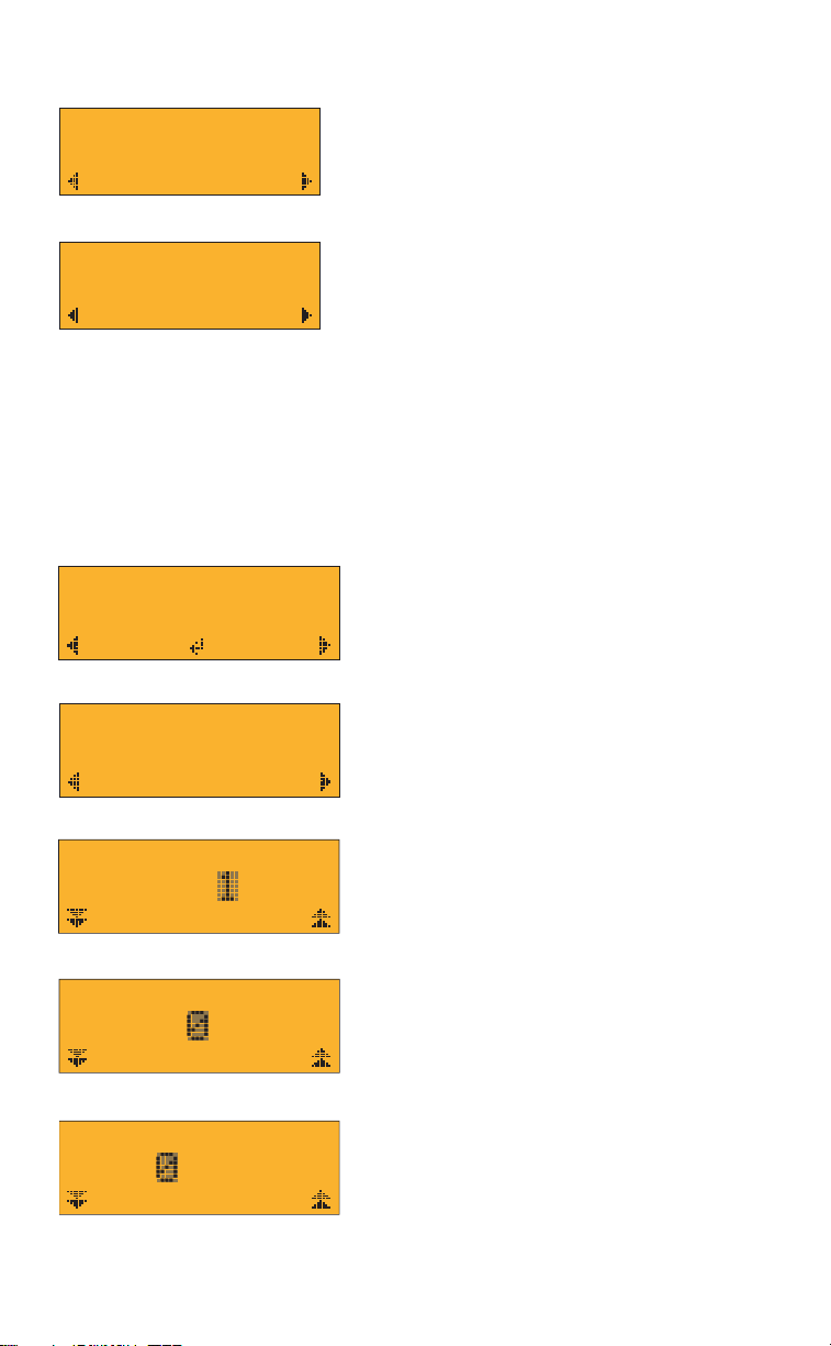
DMX Settings Screen
Smooth = Smoothing (s = ON, <blank> = OFF)
DMX = DMX Bit Rate (8b = 8-bit, 16b = 16 bit)
Curve = Dimmer Response (Std = Standard; EXP = Exponential)
DMX Mode Screen
H= Hybrid (Single Circuit*)
8= DMX Bit Rate (8 = 8-bit, 16 = 16-bit)
s = Smoothing (s = ON, <blank> = OFF)
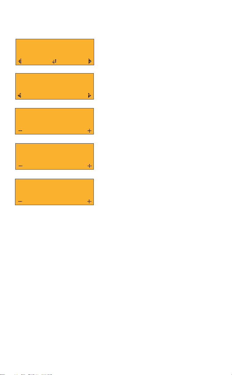
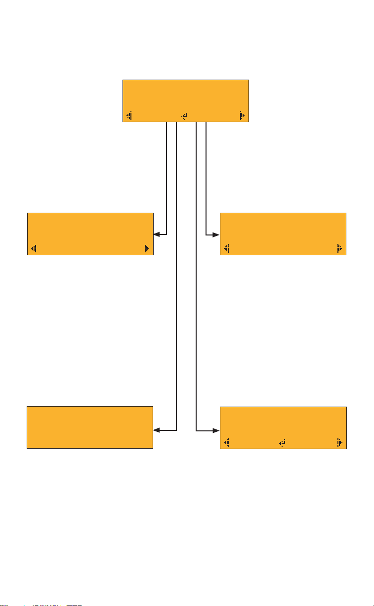
UNDERSTANDING YOUR DMX MODE SCREENS
DMX Mode Screen
Settings Screen
1) Navigate to the DMX Address Screen from
the Home Screen by pressing the right
button ( ▶).
2) Press the center button (Edit) from the DMX
Address Screen to begin editing the DMX
start address. A cursor will begin ashing over
the lowest digit of the DMX start address.
3) Use the right button ( ) to increase and the
left button ( ) to decrease the right digit.
When the desired value is displayed, press
the center button (Next) to advance to the
center digit.
4) Repeat Step #3 for the remaining digits.
5) When satised with the value of the nal
digit, press the center button (OK) to conrm
the DMX start address.
Note: The AC400 DMX 4x8 operates with
Hybrid functionality, which means the DMX
start address corresponds to the intensity
control while the next consecutive address
corresponds to the CCT control. For example,
if the DMX start address is 357, then DMX
channel 357 is intensity and channel 358 is CCT.
SETTING DMX START ADDRESS
To set the DMX start address for the AC400 DMX 4x8, complete the following steps:
DMX Addr
001
Edit
Addr
Mode
Bitrate
001
Hy1
8
New Addr
001
Next
New Addr
001
Next
New Addr
001
OK
CCT
2600k 0%
Mstr
DMX Addr
001
Edit
Addr
Mode
Bitrate
001
Hy1
8
New Addr
001
Next
New Addr
001
Next
New Addr
001
OK
CCT
2600k 0%
Mstr
DMX Hz 044
▶▶
▶▶
DMX Addr
001
Edit
Addr
Mode
Bitrate
001
Hy1
8
New Addr
001
Next
New Addr
001
Next
New Addr
001
OK
CCT
2600k 0%
Mstr
DMX Hz 044
DMX Addr
001
Edit
Addr
Mode
Bitrate
001
Hy1
8
New Addr
001
Next
New Addr
001
Next
New Addr
001
OK
CCT
2600k 0%
Mstr
DMX Hz 044
DMX Addr
001
Edit
Addr
Mode
Bitrate
001
Hy1
8
New Addr
001
Next
New Addr
001
Next
New Addr
001
OK
CCT
2600k 0%
Mstr
DMX Hz 044
Home Screen (Step 1)
DMX Address Screen (Step 2)
DMX Address Screen (Step 3)
DMX Address Screen (Step 4)
DMX Address Screen (Step 5)
* ”Single Circuit” means that the entire unit functions as a single unit. For example; you cannot control
one half of the luminaire separately from the other half.