manuals.online logo
Brands
  1. Home
  2. •
  3. Brands
  4. •
  5. Little Giant
  6. •
  7. Water Pump
  8. •
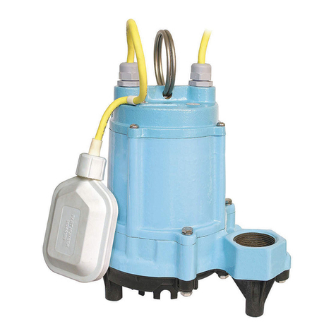
  9. Little Giant 5-ASP-FS User manual

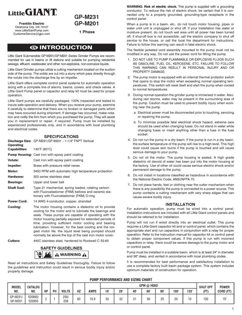
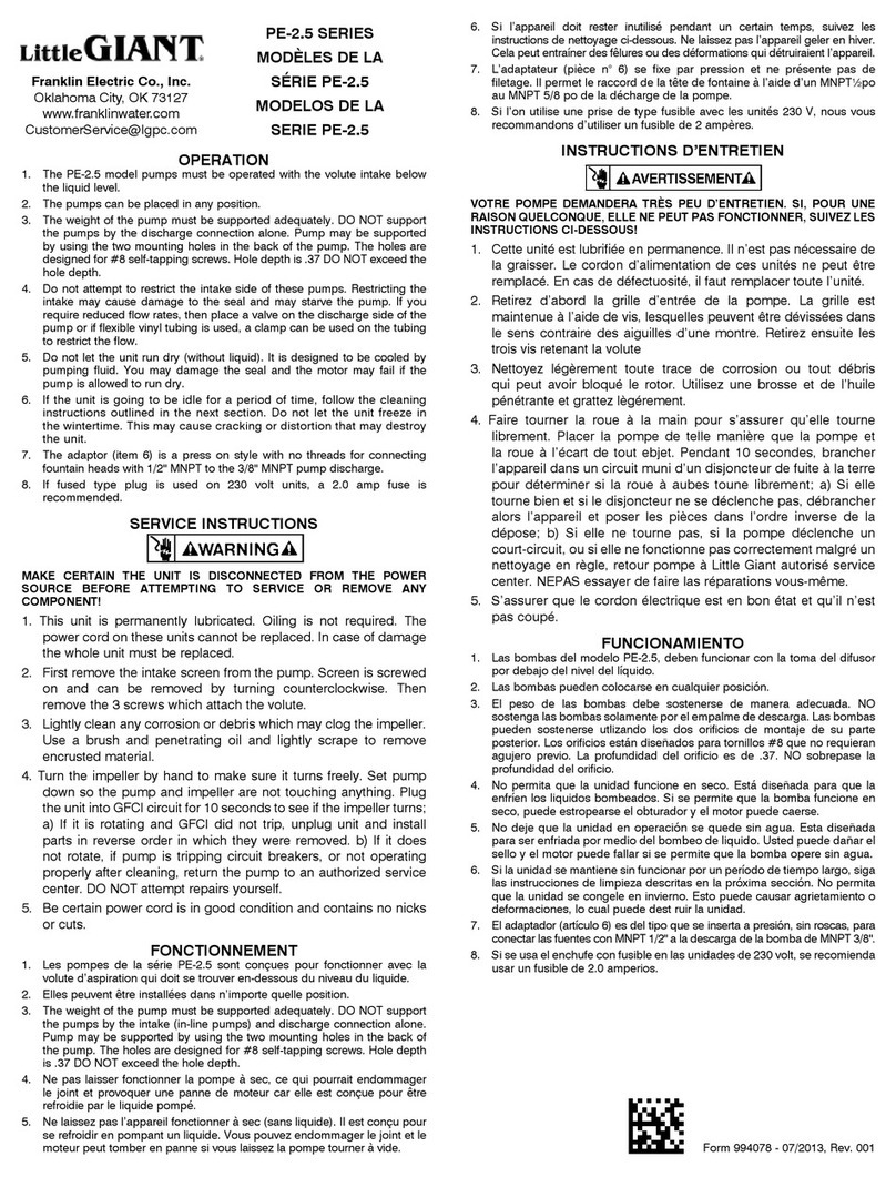
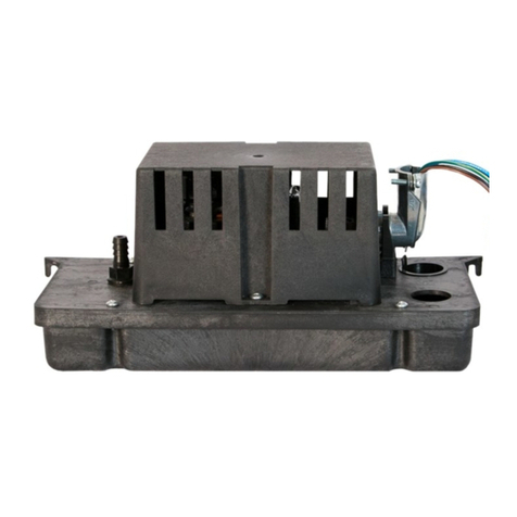
Little Giant 5-ASP-FS User manual

1
INTRODUCTION
This instruction sheet provides you with the information required
to safely own and operate your Little Giant pump. Retain these
instructions for future reference.
The Little Giant pump you have purchased is of the highest quality
workmanship and material, and has been engineered to give you
long and reliable service. Little Giant pumps are carefully tested,
inspected, and packaged to ensure safe delivery and operation.
Please examine your pump carefully to ensure that no damage
occurred during shipment. If damage has occurred, please
contact the place of purchase. They will assist you in replacement
or repair, if required.
READ THESE INSTRUCTIONS CAREFULLY BEFORE
ATTEMPTING TO INSTALL, OPERATE, OR SERVICE YOUR
LITTLE GIANT PUMP. KNOW THE PUMP’S APPLICATION,
LIMITATIONS, AND POTENTIAL HAZARDS. PROTECT
YOURSELF AND OTHERS BY OBSERVING ALL SAFETY
INFORMATION. FAILURE TO COMPLY WITH THESE
INSTRUCTIONS COULD RESULT IN PERSONAL INJURY AND/
OR PROPERTY DAMAGE!
SAFETY GUIDELINES
1. CAUTION: To reduce risk of electric shock, pull plug before
servicing this pump.
2. This pump is designed to pump water. DO NOT PUMP strong
chemicals, solvents, brines, or thick liquids such as oils or
grease.
3. Do not pump flammable liquids such as gasoline or fuel oil.
4. During operation the area around the pump may be covered
with water. Take care when handling the pump. Do not pull
pump out of water when running by the power cord.
5. Do not stand in water when changing fuse.
6. Make sure outlet is grounded.
7. The National Electric Code requires a Ground Fault Circuit
Interrupter (GFCI) be installed in the branch circuit supplying
fountain equipment, ponds, etc. See your local electrical
supply dealer for various brands of GFCI devices.
8. This pump’s motor housing is filled with a dielectric lubricant
at the factory for optimum motor heat transfer and lifetime
lubrication of the bearings. Use of any other lubricant could
cause damage and void the warranty. This lubricant is non-
toxic; however, if it escapes the motor housing, it should be
removed from the surface quickly by placing newspapers or
other absorbent material on the water surface to soak it up, so
aquatic life is undisturbed.
ELECTRICAL CONNECTIONS
Your pump is supplied with a 3-prong electrical plug. The third
prong is to ground the pump to prevent possible electrical shock
hazard. Do not remove the third prong from the plug.
A separate branch circuit is recommended. Do not use an
extension cord.
INSTALLATION
1. Clean any debris from the sump pit and set the pump in the
center of the pit. A solid bottom will prevent sand and dirt from
clogging the pump.
2. Connect the discharge piping and run it to the nearest sewer
or surface outlet. Use pipe joint compound at all connections.
Sump pumps can be piped to discharge into the house
drainage system, to a dry well, splash block, or to a a storm
drain, depending on local plumbing codes. The discharge pipe
should be as short as possible and contain as few elbows as
possible. The discharge pipe should be the same diameter as
the discharge size to reduce pipe friction losses. Smaller pipe
will restrict capacity and reduce pump performance. The sump
pump comes with 1” female pipe thread discharge.
3. Always install a union in the discharge line, just above the sump
pit, to allow for easy removal of the pump for cleaning or repair.
4. In situations where the piping is long, the vertical discharge is
above 7 or 8 feet, or a small pit has been provided, use of a
check valve is recommended to prevent backflow of water into
the sump. When a check valve is used, drill a relief hole (1/8”
or 3/16” diameter) in the discharge pipe. This hole should be
located below the floor line between the pump discharge and
the check valve. Unless such a relief hole is provided, the pump
could air lock and will not pump water even though it will run.
5. Tape the switch cord and pump cord to the discharge line with
electrician’s tape. This will protect the cords from damage and
will prevent them from interfering with the float.
6. TEST THE PUMP AFTER ALL CONNECTIONS HAVE BEEN
MADE. Run water into sump. Do not attempt to operate the
pump without water; this will damage the seals and bearings
and could result in permanent damage to the pump. Fill sump
WATER WIZARD
AUTOMATIC
SUMP PUMP
5-ASP-FS
Little Giant
P. O. Box 12010
Oklahoma City, OK 73157-2010
405.947.2511 • Fax: 405.947.8720
www.LittleGiantPump.com
[email protected]
2
to normal “on” level and allow pump to remove water to the
normal “off” level (Figure 1).
7. Place the cover over the sump. This cover will prevent solid
debris from filling the pit, reduce odors, and guard against
accidental injury.
MAINTENANCE
The motor housing of the pump is completely sealed and requires
no service. Disassembly of the motor housing or alteration of the
power cord voids all warranty.
The motor is continuous duty type sealed in oil with an automatic
thermal overload protector device.
The pump can run against a restricted discharge (such as a
fountain) without damage to the pump.
1. If the pump becomes clogged, snap the screen off and clean
out the area.
2. If necessary, remove the six screws holding the volute base to
the motor housing and clean the volute.
3. If the impeller is removed, make sure that a spacing of
.050” with shaft pushed toward housing is maintained when
reassembling (Figure 2).
4. When reassembling, ensure that you install the seal ring
between the volute base and the motor housing.
PERFORMANCE DATA
Maximum pumping height = 26.3’
Maximum PSI = 11.4 PSIG
Discharge height
above pumping level
1’ 3’ 5’ 10’ 15’ 20
Gallons per minute
(water)
20.4 20 19 16 13 8
Note: Ratings based on 1” pipe with friction loss neglected.
Using 3/4” garden hose adaptor performance will be reduced
approximately 15%. This pump does not deliver enough pressure
to operate lawn sprinklers properly.
FIGURE 1
TYPICAL INSTALLATION
FIGURE 2
3
REPLACEMENT PARTS LIST
Item
No.
Part
No.
Description Catalog No.
505400 505401
1 902441 Screw, #8 x 1-5/8” 2 2
2 105918 Handle 1 1
3 599030 Adaptor 1 1
4 105310 Impeller 1 1
5 928024 Seal ring 1 1
6 105375 Volute base 1 1
7 902434 Screw, #8-18 x 3/4” 6 6
8 105376 Screen 1 1
9 902431 Screw, #8-18 x 1/2” 1 1
10 927030 Loop clamp 1 1
4
3. Cord cut off to a length less than three feet.
4. Pump allowed to operate dry (fluid supply cut off).
5. Pump used to circulate anything other than fresh water at
approximately room temperature.
6. Product abuse by customer.
Any oral statements about the product made by the seller, the
manufacturer, the representatives or any other parties, do not
constitute warranties, shall not be relied upon by the user and are
not part of the contract for sale. Seller’s and manufacturer’s only
obligation, and buyer’s only remedy, shall be the replacement and/
or repair by the manufacturer of the product as described above.
NEITHER SELLER NOR THE MANUFACTURER SHALL BE LIABLE
FOR ANY INJURY, LOSS OR DAMAGE, DIRECT, INCIDENTAL OR
CONSEQUENTIAL (INCLUDING, BUT NOT LIMITED TO INCIDENTAL
OR CONSEQUENTIAL DAMAGES FOR LOST PROFITS, LOST SALES,
INJURY TO PERSON OR PROPERTY, OR ANY OTHER INCIDENTAL
OR CONSEQUENTIAL LOSS), ARISING OUT OF THE USE OR THE
INABILITY TO USE THE PRODUCT AND THE USER AGREES THAT
NO OTHER REMEDY SHALL BE AVAILABLE TO IT. Before using,
the user shall determine the suitability of the product for the intended
use, and user assumes all risk and liability whatsoever in connection
therewith.
Some states and countries do not allow limitations on how long
an implied warranty lasts or the exclusion or limitation of incidental
or consequential damages, so the above limitations or exclusions
may not apply to you. This warranty gives you specific legal rights,
and you may also have other rights which vary from state to state
and country to country.
The National Electric Code (in the USA) and similar codes in other
countries require a Ground Fault Circuit Interrupter (GFCI) to be
installed in the branch circuit supplying fountain equipment rated
above 15 volts. 115 volt GFCI’s (with various cord lengths) are in
stock, and we recommend each pump be used with a GFCI.
Your Little Giant product is guaranteed to be in perfect condition
when it leaves our Factory. It is warranted against defective
materials and workmanship for a period of 12 months (90 day
warranty on Models: 1-AA-OM, GKPK-SC, PP Series, PPS Series,
and Cooler King) from date of purchase by the user. No warranty
on brush wear in Model 35-OM and impeller or cam in PP Series
and PPS Series.
Any product that should fail for either of the above two reasons
and is still within the warranty period will be repaired or replaced
at the option of Little Giant as the sole remedy of buyer. For our
customers in the CONTINENTAL UNITED STATES: Please return
the defective unit, postage paid, to the factory at 301 N. MacArthur,
Oklahoma City, OK 73127-6616. All defective product returned
under warranty will be fully inspected to determine the cause of
failure before warranty is approved.
For our customers located elsewhere; it is not economical, due to
duties and freight, to return the pump to the factory for inspection.
Please return the defective unit to any authorized distributor or
dealer with a brief written explanation of the problem. If there
are no apparent signs of customer abuse, unit will be repaired
or replaced. If dispute arises over replacement of the pump,
the distributor or dealer is to segregate such items and hold for
inspection by a representative of Little Giant Pump Company or
notify factory with details of the problem for factory disposition and
settlement of warranty claim.
DISCLAIMER: THE FOREGOING WARRANTY IS AN EXCLUSIVE
WARRANTY IN LIEU OF ANY OTHER EXPRESS WARRANTIES.
ANY IMPLIED WARRANTIES (INCLUDING, BUT NOT LIMITED TO
ANY IMPLIED WARRANTY OF MERCHANTABILITY OR FITNESS
FOR A PARTICULAR PURPOSE) TO THE EXTENT EITHER
APPLIES TO A PUMP SHALL BE LIMITED IN DURATION TO THE
PERIODS OF THE EXPRESS WARRANTIES GIVEN ABOVE.
Warranty will be VOID if any of the following conditions are found:
1. Sealed motor housing opened.
2. Product connected to voltage other than indicated on nameplate.
Form 993157 - 07/2007
© 2007 Franklin Electric Co., Inc.
Little Giant® is a registered trademark of Franklin Electric Co., Inc.
For parts or repair, please contact . . . . . . . . . . . . . . . . . . . . 1.888.572.9933
For technical assistance, please contact . . . . . . . . . . . . . . . 1.888.956.0000
www.LittleGiantPump.com
[email protected]
LIMITED WARRANTY

Other Little Giant Water Pump manuals

Little Giant PWM Series User manual

Little Giant

Little Giant PWM Series User manual

Little Giant 16EH-CIM Reference manual

Little Giant

Little Giant 16EH-CIM Reference manual

Little Giant PE-1 User manual

Little Giant

Little Giant PE-1 User manual

Little Giant Pit+Plus JR User manual

Little Giant

Little Giant Pit+Plus JR User manual

Little Giant CS-SS User manual

Little Giant

Little Giant CS-SS User manual

Little Giant 15SC-CIA-RF User manual

Little Giant

Little Giant 15SC-CIA-RF User manual

Little Giant CONDENCATE Series User manual

Little Giant

Little Giant CONDENCATE Series User manual

Little Giant VCMX-20 User manual

Little Giant

Little Giant VCMX-20 User manual

Little Giant PCS-10 User manual

Little Giant

Little Giant PCS-10 User manual

Little Giant CMD-100-3B User manual

Little Giant

Little Giant CMD-100-3B User manual

Little Giant JBAK User manual

Little Giant

Little Giant JBAK User manual

Little Giant 1-AA-18 User manual

Little Giant

Little Giant 1-AA-18 User manual

Little Giant 2E-NDVR User manual

Little Giant

Little Giant 2E-NDVR User manual

Little Giant 5 Series User manual

Little Giant

Little Giant 5 Series User manual

Little Giant VCMX-20 User manual

Little Giant

Little Giant VCMX-20 User manual

Little Giant CP1 Series User manual

Little Giant

Little Giant CP1 Series User manual

Little Giant WRS-5 User manual

Little Giant

Little Giant WRS-5 User manual

Little Giant WRS-5 User manual

Little Giant

Little Giant WRS-5 User manual

Little Giant 10S-CIA-RFS User manual

Little Giant

Little Giant 10S-CIA-RFS User manual

Little Giant OPWG SERIES User manual

Little Giant

Little Giant OPWG SERIES User manual

Little Giant Simply Falls User manual

Little Giant

Little Giant Simply Falls User manual

Little Giant 1-YS User manual

Little Giant

Little Giant 1-YS User manual

Little Giant 5-ASP-FS User manual

Little Giant

Little Giant 5-ASP-FS User manual

Little Giant VCMA Series User manual

Little Giant

Little Giant VCMA Series User manual

Popular Water Pump manuals by other brands

GORMAN-RUPP PUMPS PA6C60-4045T FT4 Installation, operation, and maintenance manual with parts list

GORMAN-RUPP PUMPS

GORMAN-RUPP PUMPS PA6C60-4045T FT4 Installation, operation, and maintenance manual with parts list

vacuubrand RC 6 Instructions for use

vacuubrand

vacuubrand RC 6 Instructions for use

MULTIQUIP MAYCO LS300P Operation manual

MULTIQUIP

MULTIQUIP MAYCO LS300P Operation manual

Ruris MP 200XR manual

Ruris

Ruris MP 200XR manual

EBARA 3D Operating and maintenance manual

EBARA

EBARA 3D Operating and maintenance manual

Simer 2700 owner's manual

Simer

Simer 2700 owner's manual

Goulds IM105R06 instruction manual

Goulds

Goulds IM105R06 instruction manual

Allfett LUBMATIC MINI Series INTRODUCTION AND USER MANUAL

Allfett

Allfett LUBMATIC MINI Series INTRODUCTION AND USER MANUAL

Wilden HX400S manual

Wilden

Wilden HX400S manual

Graco 29:1 Lube Pro instructions

Graco

Graco 29:1 Lube Pro instructions

Graco Dura-Flo Instructions-parts list

Graco

Graco Dura-Flo Instructions-parts list

YATO YT-85300 Original instructions

YATO

YATO YT-85300 Original instructions

Marina 75 instruction manual

Marina

Marina 75 instruction manual

Flotec 1100X Series quick start guide

Flotec

Flotec 1100X Series quick start guide

Grundfos alpha2 l Installation and operating instructions

Grundfos

Grundfos alpha2 l Installation and operating instructions

Grundfos DMX 221 Installation and operating instructions

Grundfos

Grundfos DMX 221 Installation and operating instructions

Becker VX 4.10 operating instructions

Becker

Becker VX 4.10 operating instructions

Oase AquaMax Eco Premium 6000/12 V manual
Oase

Oase AquaMax Eco Premium 6000/12 V manual

manuals.online logo
manuals.online logoBrands
  • About & Mission
  • Contact us
  • Privacy Policy
  • Terms and Conditions

Copyright 2025 Manuals.Online. All Rights Reserved.