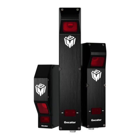
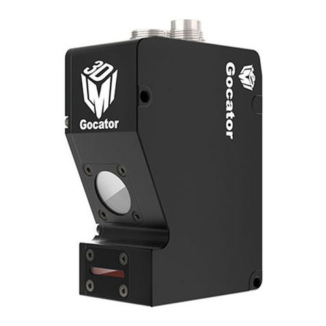
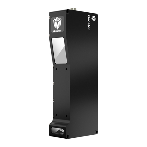
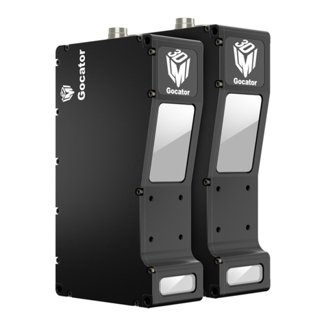
LMI Technologies Gocator 3210 User manual

USER MANUAL
Gocator Snapshot Sensors
Gocator 3210 &3506
Firmware version:4.7.x.xx
Document revision:C

Gocator Snapshot Sensors: User Manual 2
Copyright
Copyright © 2017 by LMI Technologies, Inc. All rights reserved.
Proprietary
This document, submitted in confidence, contains proprietary information which shall not be
reproduced or transferred to other documents or disclosed to others or used for manufacturing or any
other purpose without prior written permission of LMI Technologies Inc.
No part of this publication may be copied, photocopied, reproduced, transmitted, transcribed, or
reduced to any electronic medium or machine readable form without prior written consent of LMI
Technologies, Inc.
Trademarks and Restrictions
Gocator™ is a registered trademark of LMI Technologies, Inc. Any other company or product names
mentioned herein may be trademarks of their respective owners.
Information contained within this manual is subject to change.
This product is designated for use solely as a component and as such it does not comply with the
standards relating to laser products specified in U.S. FDA CFR Title 21 Part 1040.
Contact Information
LMI Technologies, Inc.
9200 Glenlyon Parkway
Burnaby BCV5J 5J8
Canada
Telephone: +1 604-636-1011
Fax: +1 604-516-8368
www.lmi3D.com

Gocator Snapshot Sensors: User Manual 3
Table of Contents
Copyright 2
Table of Contents 3
Introduction 11
Gocator Overview 12
Safety and Maintenance 13
Electrical Safety 13
Handling, Cleaning, and Maintenance 13
Environment and Lighting 14
Getting Started 15
Hardware Overview 16
Gocator Sensor 16
Gocator 3x00 Cordsets 16
Master 100 17
Master 400 / 800 / 1200 / 2400 18
Master 810 / 2410 19
System Overview 21
Standalone System 21
Multi-Sensor System 21
Installation 23
Mounting 23
Grounding 23
Gocator 24
Recommended Practices for Cordsets 24
Master Network Controllers 25
Grounding When Using a DIN Rail (Master
810/2410) 25
Installing DIN Rail Clips: Master 810 or 2410 26
Configuring Master 810 27
Setting the Divider 27
Encoder Quadrature Frequency 28
Setting the Debounce Period 28
Network Setup 30
Client Setup 30
Gocator Setup 32
Running a Standalone Sensor System 32
Running a Multi-Sensor System 33
Next Steps 35
How Gocator Works 36
3D Acquisition 36
Clearance Distance, Field of Viewand 38
Measurement Range
Stereo Correlation vs. Independent
Triangulation 38
3DData Output 40
Coordinate Systems 40
Sensor Coordinates 40
System Coordinates 41
Resampling 42
Data Generation and Processing 42
Part Detection 43
Sectioning 43
Part Matching 43
Measurement and Anchoring 43
Output and Digital Tracking 44
Gocator Web Interface 45
Unblocking Flash 45
Google Chrome 45
Internet Explorer 46
Firefox 47
Microsoft Edge 48
User Interface Overview 50
Toolbar 51
Creating, Saving and Loading Jobs (Settings) 52
Recording, Playback, and Measurement
Simulation 53
Recording Filtering 55
Downloading, Uploading, and Exporting
Replay Data 56
Metrics Area 59
Data Viewer 59
Status Bar 59
Log 60
Frame Information 60
Interface Language 61
Quick Edit Mode 61
Management and Maintenance 62
Manage Page Overview 62
Sensor System 63
Sensor Autostart 63
Networking and Power 63
Motion and Alignment 64
Alignment Reference 65
Jobs 65

Gocator Snapshot Sensors: User Manual 4
Security 67
Maintenance 68
Sensor Backups and Factory Reset 69
Firmware Upgrade 70
Support 71
Support Files 71
Manual Access 72
Software Development Kit 72
Scan Setup and Alignment 74
Scan Page Overview 74
Scan Modes 75
Triggers 75
Trigger Examples 77
Trigger Settings 78
Maximum Input Trigger Rate 79
Maximum Encoder Rate 79
Sensor 79
Reduce Occlusion 79
Active Area 80
Transformations 82
Exposure 83
Single Exposure 84
Multiple Exposure 87
Spacing 90
Spacing Interval 90
Advanced 90
Material 91
Camera Gain 92
Alignment 92
Alignment States 93
Alignment Types 93
Aligning Sensors 93
Clearing Alignment 94
Filters 95
Gap Filling 95
Median 96
Smoothing 97
Decimation 97
Part Detection 98
Edge Filtering 100
Data Viewer 102
Data Viewer Controls 102
Video Mode 103
Exposure Information 103
Exposures 103
Overexposure and Underexposure 104
Surface Mode 106
Height Map Color Scale 108
Sections 109
Region Definition 111
Intensity Output 111
Models 112
Model Page Overview 112
Part Matching 113
Using Edge Detection 114
Creating a Model 117
Modifying a Model's Edge Points 119
Adjusting Target Sensitivity 122
Setting the Match Acceptance Criteria 123
Running Part Matching 123
Using Bounding Box and Ellipse 123
Configuring a Bounding Box or an Ellipse125
Running Part Matching 126
Using Part Matching to Accept or Reject a
Part 127
Sections 127
Creating a Section 130
Deleting a Section 132
Measurement 133
Measure Page Overview 133
Data Viewer 134
Tools Panel 134
Adding and Configuring a Measurement
Tool 134
Source 135
Streams (Sections) 135
Regions 136
Feature Points 138
Fit Lines 140
Geometric Features 141
Decisions 142
Filters 143
Measurement Anchoring 145
Enabling and Disabling Measurements 150
Editing a Tool or Measurement Name 151

Gocator Snapshot Sensors: User Manual 5
Changing a Measurement ID 151
Duplicating a Tool 152
Removing a Tool 152
Reordering Tools 153
Profile Measurement 153
Area 153
Measurements, Features, and Settings 155
Bounding Box 157
Measurements, Features, and Settings 158
Circle 159
Measurements, Features, and Settings 160
Dimension 161
Groove 164
Intersect 168
Measurements, Features, and Settings 168
Line 170
Measurements, Features, and Settings 171
Panel 174
Position 177
Measurements, Features, and Settings 178
Round Corner 180
Strip 183
Script 187
Surface Measurement 189
Bounding Box 189
Measurements, Features, and Settings 191
Countersunk Hole 193
Measurements, Features, and Settings 196
Dimension 202
Edge 206
Paths and Path Profiles 209
Measurements, Features, and Settings 210
Ellipse 220
Measurements, Features, and Settings 221
Hole 223
Measurements, Features, and Settings 225
Measurement Region 227
Opening 228
Measurements, Features, and Settings 231
Measurement Region 235
Plane 235
Measurements, Features, and Settingss 238
Position 239
Measurements, Features, and Settingss 240
Stud 242
Measurements, Features, and Settings 244
Measurement Region 246
Volume 246
Script 248
Feature Measurement 249
Dimension 249
Intersect 252
Scripts 256
Built-in Functions 257
Output 262
Output Page Overview 262
Ethernet Output 263
Digital Output 267
Analog Output 270
Serial Output 271
Dashboard 274
Dashboard Page Overview 274
State and Health Information 274
Statistics 276
Measurements 276
Performance 276
Gocator Emulator 278
System Requirements 278
Limitations 279
Downloading a Support File 279
Running the Emulator 280
Adding a Scenario to the Emulator 281
Running a Scenario 281
Removing a Scenario from the Emulator 282
Using Replay Protection 283
Stopping and Restarting the Emulator 283
Running the Emulator in Default Browser 283
Working with Jobs and Data 284
Creating, Saving, and Loading Jobs 284
Playback and Measurement Simulation 285
Downloading, Uploading, and Exporting
Replay Data 286
Downloading and Uploading Jobs 288
Scan, Model, and Measurement Settings 290

Gocator Snapshot Sensors: User Manual 6
Calculating Potential Maximum Frame Rate 290
Protocol Output 291
Remote Operation 291
Gocator Accelerator 293
System Requirements 294
Benefits 294
Installation 294
Gocator Accelerator Utility 294
Dashboard and Health Indicators 297
SDK Application Integration 297
Gocator Device Files 299
Live Files 299
Log File 299
Job File Structure 300
Job File Components 300
Accessing Files and Components 301
Configuration 301
Setup 302
Filters 303
XSmoothing 303
YSmoothing 303
XGapFilling 304
YGapFilling 304
XMedian 304
YMedian 304
XDecimation 305
YDecimation 305
XSlope 305
YSlope 305
Trigger 306
Layout 307
Alignment 308
Disk 309
Bar 309
Plate 310
Devices / Device 310
Tracking 312
Material 313
IndependentExposures 315
SurfaceGeneration 315
FixedLength 316
VariableLength 316
Rotational 316
SurfaceSections 317
ProfileGeneration 317
FixedLength 318
VariableLength 318
Rotational 318
PartDetection 318
EdgeFiltering 320
PartMatching 320
Edge 320
BoundingBox 320
Ellipse 321
Replay 322
RecordingFiltering 322
Conditions/AnyMeasurement 322
Conditions/AnyData 323
Conditions/Measurement 323
Streams/Stream (Read-only) 323
ToolOptions 324
MeasurementOptions 325
FeatureOptions 325
StreamOptions 326
Tools 326
Profile Types 326
ProfileFeature 326
ProfileLine 327
ProfileRegion2d 327
SurfaceTypes 327
Region3D 327
SurfaceFeature 327
SurfaceRegion2d 328
Geometric Feature Types 328
Parameter Types 328
ProfileArea 330
ProfileBoundingBox 332
ProfileCircle 333
ProfileDimension 335
ProfileGroove 336
ProfileIntersect 338
ProfileLine 340
ProfilePanel 342
ProfilePosition 344

Gocator Snapshot Sensors: User Manual 7
ProfileRoundCorner 345
ProfileStrip 347
Script 349
SurfaceBoundingBox 350
SurfaceCsHole 352
SurfaceDimension 355
Tool 356
SurfaceEllipse 359
SurfaceHole 361
SurfaceOpening 363
SurfacePlane 365
SurfacePosition 367
SurfaceStud 369
SurfaceVolume 371
Tool 373
Tool 374
Custom 376
Output 376
Ethernet 377
Ascii 379
EIP 380
Modbus 380
Digital0 and Digital1 380
Analog 381
Serial 382
Selcom 382
Ascii 383
Transform 383
Device 384
Part Models 384
Edge Points 385
Configuration 386
Protocols 387
Gocator Protocol 387
Data Types 388
Commands 388
Discovery Commands 389
Get Address 389
Set Address 390
Get Info 391
Control Commands 392
Protocol Version 393
Get Address 393
Set Address 393
Get System Info V2 394
Get System Info 396
Get States 397
Log In/Out 398
Change Password 399
Set Buddy 399
List Files 400
Copy File 400
Read File 401
Write File 401
Delete File 402
User Storage Used 402
User Storage Free 403
Get Default Job 403
Set Default Job 403
Get Loaded Job 404
Get Alignment Reference 404
Set Alignment Reference 405
Clear Alignment 405
Get Timestamp 406
Get Encoder 406
Reset Encoder 406
Start 407
Scheduled Start 407
Stop 408
Get Auto Start Enabled 408
Set Auto Start Enabled 408
Get Voltage Settings 409
Set Voltage Settings 409
Get Quick Edit Enabled 409
Set Quick Edit Enabled 410
Start Alignment 410
Start Exposure Auto-set 411
Software Trigger 411
Schedule Digital Output 412
Schedule Analog Output 412
Ping 413
Reset 413
Backup 414
Restore 414

Gocator Snapshot Sensors: User Manual 8
Restore Factory 414
Get Recording Enabled 415
Set Recording Enabled 415
Clear Replay Data 416
Get Playback Source 416
Set Playback Source 416
Simulate 417
Seek Playback 417
Step Playback 418
Playback Position 418
Clear Measurement Stats 419
Read Live Log 419
Clear Log 420
Simulate Unaligned 420
Acquire 420
Acquire Unaligned 421
Create Model 421
Detect Edges 421
Add Tool 422
Add Measurement 422
Read File (Progressive) 423
Export CSV (Progressive) 423
Export Bitmap (Progressive) 424
Get Runtime Variable Count 425
Set Runtime Variables 425
GetRuntimeVariables 426
Upgrade Commands 426
Start Upgrade 427
Start Upgrade Extended 427
Get Upgrade Status 427
Get Upgrade Log 428
Results 428
Data Results 428
Stamp 429
Video 430
Surface 430
Surface Intensity 431
Surface Section 432
Surface Section Intensity 433
Measurement 433
Operation Result 434
Exposure Calibration Result 434
Edge Match Result 435
Bounding Box Match Result 435
Ellipse Match Result 436
Event 436
Feature Point 436
Feature Line 437
Health Results 437
Modbus Protocol 443
Concepts 443
Messages 443
Registers 444
Control Registers 445
Output Registers 446
State 446
Stamp 447
Measurement Registers 448
EtherNet/IP Protocol 450
Concepts 450
Basic Object 451
Identity Object (Class 0x01) 451
TCP/IP Object (Class 0xF5) 451
Ethernet Link Object (Class 0xF6) 451
Assembly Object (Class 0x04) 452
Command Assembly 452
Runtime Variable Configuration Assembly 453
Sensor State Assembly 454
Sample State Assembly 455
Implicit Messaging Command Assembly 456
Implicit Messaging Output Assembly 457
ASCIIProtocol 459
Connection Settings 459
Ethernet Communication 459
Serial Communication 460
Polling Operation Commands (Ethernet Only) 460
Command and Reply Format 461
Special Characters 461
Command Channel 461
Start 461
Stop 462
Trigger 462
LoadJob 463
Stamp 463

Gocator Snapshot Sensors: User Manual 9
Clear Alignment 463
Stationary Alignment 464
Set Runtime Variables 464
Get Runtime Variables 464
Data Channel 465
Result 465
Value 466
Decision 466
Health Channel 467
Health 467
Standard Result Format 467
Custom Result Format 468
Development Kits 470
GoSDK 470
Setup and Locations 471
Class Reference 471
Examples 471
Sample Project Environment Variable 471
Header Files 471
Class Hierarchy 471
GoSystem 472
GoSensor 472
GoSetup 472
GoLayout 472
GoTools 473
GoTransform 473
GoOutput 473
Data Types 473
Value Types 473
Output Types 473
GoDataSet Type 474
MeasurementValues and Decisions 475
Operation Workflow 475
Initialize GoSdk APIObject 476
Discover Sensors 477
Connect Sensors 477
Configure Sensors 477
Enable Data Channels 477
Perform Operations 477
Limiting Flash Memory Write Operations 479
GDK 480
Benefits 480
Supported Sensors 480
Typical Workflow 481
Installation and Class Reference 481
Required Tools 481
Getting Started with the Example Code 482
Building the Sample Code 482
Tool Registration 482
Tool Definitions 483
Entry Functions 483
Parameter Configurations 484
Graphics Visualization 485
Debugging Your Measurement Tools 487
Debugging Entry Functions 488
Tips 488
Backward Compatibility with Older Versions
of Tools 488
Define new parameters as optional 488
Configuration Versioning 488
Version 490
Common Programming Operations 490
Input Data Objects 490
Setup and Region Info during Tool
Initialization 491
Computing Region Based on the Offset
from an Anchor Source 491
Part Matching 492
Accessing Sensor Local Storage 492
Print Output 492
Tools and Native Drivers 493
Sensor Discovery Tool 493
GenTL Driver 494
16-bit RGB Image 498
16-bit Grey Scale Image 499
Registers 501
XMLSettings File 502
Interfacing with Halcon 502
Setting Up Halcon 503
Halcon Procedures 506
Generating Halcon Acquisition Code 510
CSV Converter Tool 511
MountainsMap Transfer Tool 513
Configuring Gocator to Work with the Transfer
Tool 514

Gocator Snapshot Sensors: User Manual 10
Using the Mountains Map Transfer Tool 514
Troubleshooting 517
Specifications 519
Sensors 519
Gocator 3210 Sensor 520
Gocator 3210 522
Gocator 3506 Sensor 525
Gocator 3506 526
Estimated Scan Rates 528
Sensor Connectors 530
Gocator Power/LAN Connector 530
Grounding Shield 530
Power 531
Safety Input 531
Gocator I/O Connector 532
Grounding Shield 532
Digital Outputs 532
Inverting Outputs 533
Digital Input 533
Encoder Input 534
Serial Output 535
Analog Output 535
Master Network Controllers 536
Master 100 536
Master 100 Dimensions 537
Master 400/800 538
Master 400/800 Electrical Specifications 539
Master 400/800 Dimensions 540
Master 810/2410 541
Electrical Specifications 543
Encoder 544
Input 546
Master 810 Dimensions 548
Master 2410 Dimensions 549
Master 1200/2400 550
Master 1200/2400 Electrical Specifications 551
Master 1200/2400 Dimensions 552
Accessories 553
Return Policy 555
Software Licenses 556
Support 562
Contact 563

Gocator Snapshot Sensors: User Manual 11
Introduction
This documentation describes how to connect, configure, and use a Gocator. It also contains reference
information on the device's protocols and job files, as well as an overview of the development kits you
can use with Gocator. Finally, the documentation describes the Gocator emulator and accelerator
applications.
The documentation applies to the following sensors:
lGocator 3210
lGocator 3506
Notational Conventions
This documentation uses the following notational conventions:
Follow these safety guidelines to avoid potential injury or property damage.
Consider this information in order to make best use of the product.

Gocator Snapshot Sensors: User Manual 12
Gocator Overview
Gocator snapshot LED projection sensors are designed for 3D measurement and control applications.
Gocator sensors are configured using a web browser and can be connected to a variety of input and
output devices. Gocator sensors can also be configured using the provided development kits.

Gocator Snapshot Sensors: User Manual 13
Safety and Maintenance
The following sections describe the safe use and maintenance of Gocator sensors.
Electrical Safety
Failure to follow the guidelines described in this section may result in electrical shock or equipment
damage.
Sensors should be connected to earth ground
All sensors should be connected to earth ground through their housing. All sensors should be mounted
on an earth grounded frame using electrically conductive hardware to ensure the housing of the sensor
is connected to earth ground. Use a multi-meter to check the continuity between the sensor connector
and earth ground to ensure a proper connection.
Minimize voltage potential between system ground and sensor ground
Care should be taken to minimize the voltage potential between system ground (ground reference for
I/O signals) and sensor ground. This voltage potential can be determined by measuring the voltage
between Analog_out- and system ground. The maximum permissible voltage potential is 12 V but should
be kept below 10 V to avoid damage to the serial and encoder connections.
For a description of the connector pins, see Gocator I/O Connector on page 532.
Use a suitable power supply
The +24 to +48 VDC power supply used with Gocator sensors should be an isolated supply with inrush
current protection or be able to handle a high capacitive load.
Use care when handling powered devices
Wires connecting to the sensor should not be handled while the sensor is powered. Doing so may cause
electrical shock to the user or damage to the equipment.
Handling, Cleaning, and Maintenance
Dirty or damaged sensor windows (emitter or camera) can affect accuracy. Use caution when
handling the sensor or cleaning the sensor's windows.
Keep sensor windows clean
Use dry, clean air to remove dust or other dirt particles. If dirt remains, clean the windows carefully with
a soft, lint-free cloth and non-streaking glass cleaner or isopropyl alcohol. Ensure that no residue is left
on the windows after cleaning.
Avoid excessive modifications to files stored on the sensor
Settings for Gocator sensors are stored in flash memory inside the sensor. Flash memory has an
expected lifetime of 100,000 writes. To maximize lifetime, avoid frequent or unnecessary file save

Gocator Snapshot Sensors: User Manual Safety and Maintenance • 14
operations.
Environment and Lighting
Avoid strong ambient light sources
The imager used in this product is highly sensitive to ambient light hence stray light may have adverse
effects on measurement. Do not operate this device near windows or lighting fixtures that could
influence measurement. If the unit must be installed in an environment with high ambient light levels, a
lighting shield or similar device may need to be installed to prevent light from affecting measurement.
Avoid installing sensors in hazardous environments
To ensure reliable operation and to prevent damage to Gocator sensors, avoid installing the sensor in
locations
lthat are humid, dusty, or poorly ventilated;
lwith a high temperature, such as places exposed to direct sunlight;
lwhere there are flammable or corrosive gases;
lwhere the unit may be directly subjected to harsh vibration or impact;
lwhere water, oil, or chemicals may splash onto the unit;
lwhere static electricity is easily generated.
Ensure that ambient conditions are within specifications
Gocator sensors are suitable for operation between 0–50° C and 25–85% relative humidity (non-
condensing). The storage temperature is -30–70° C.
The Master network controllers are similarly rated for operation between 0–50° C.
The sensor must be heat-sunk through the frame it is mounted to. When a sensor is properly heat
sunk, the difference between ambient temperature and the temperature reported in the sensor's
health channel is less
than 15° C.
Gocator sensors are high-accuracy devices, and the temperature of all of its components must
therefore be in equilibrium. When the sensor is powered up, a warm-up time of at least one hour is
required to reach a consistent spread of temperature in the sensor.

Gocator Snapshot Sensors: User Manual 15
Getting Started
The following sections provide system and hardware overviews, in addition to installation and setup
procedures.

Gocator Snapshot Sensors: User Manual Getting Started • 16
Hardware Overview
The following sections describe Gocator and its associated hardware.
Gocator Sensor
Gocator 3110
Item Description
Camera Observes light reflected from target surfaces.
Light Emitter Emits structured light for 3Ddata acquisition.
I/O Connector Accepts input/output signals.
Power/LAN Connector Connects to 1000 Mbit/s Ethernet network.
Power Indicator Illuminates when power is applied (blue).
Safety Indicator Illuminates when laser safety input is active (amber).
Serial Number Unique sensor serial number.
Gocator 3x00 Cordsets
G3 sensors use two types of cordsets.
The Power & Ethernet cordset provides power and safety interlock to the sensor. It is also used for
sensor communication via 1000 Mbit/s Ethernet with a standard RJ45 connector. The Master version of
the Power & Ethernet cordset provides direct connection between the sensor and a Master network
controller (excluding Master 100).
The G3 I/O cordset provides digital I/O connections, an encoder interface, RS-485 serial connection, and
an analog output.
If you use a Master 100 with a G3 sensor, you must use the latest version of the Master 100 with a metal-
shielded Master Power Port and a Power & Ethernet cordset with a metal-shielded Power/Sync RJ45 plug.

Gocator Snapshot Sensors: User Manual Getting Started • 17
The maximum cordset length is 60 m. For pinout details, Gocator I/O Connector on page 532 and Gocator
Power/LAN Connector on page 530.
See Accessories on page 553 for cordset lengths and part numbers. Contact LMI for information on
creating cordsets with customized lengths and connector orientations.
Master 100
Item Description
Master Ethernet Port Connects to the RJ45 connector labeled Ethernet on the Power/LAN to Master cordset.
Master Power Port Connects to the RJ45 connector labeled Power/Sync on the Power/LAN to Master
cordset. Provides power and laser safety to the Gocator.
Sensor I/O Port Connects to the Gocator I/O cordset.
Master Host Port Connects to the host PC's Ethernet port.
Power Accepts power (+48 V).
Power Switch Toggles sensor power.
Laser Safety Switch Toggles laser safety signal provided to the sensors [O= laser off, I= laser on].
Trigger Signals a digital input trigger to the Gocator.
Encoder Accepts encoder A, B and Z signals.
Digital Output Provides digital output.
See Master 100 on page 536 for pinout details.

Gocator Snapshot Sensors: User Manual Getting Started • 18
Master 400 / 800 / 1200 / 2400
The Master 400, 800, 1200, and 2400 network controllers let you connect more than two sensors:
lMaster 400: accepts four sensors
lMaster 800 accepts eight sensors
lMaster 1200:accepts twelve sensors
lMaster 2400:accepts twenty-four sensors
Master 400 and 800

Gocator Snapshot Sensors: User Manual Getting Started • 19
Master 1200 and 2400
Item Description
Sensor Ports Master connection for Gocator sensors (no specific order required).
Ground Connection Earth ground connection point.
Power and Safety Power and laser safety connection.
Encoder Accepts encoder signal.
Input Accepts digital input.
For pinout details for Master 400 or 800, see Master 400/800 on page 538.
For pinout details for Master 1200 or 2400, see Master 1200/2400 on page 550.
Master 810 / 2410
The Master 810 and 2410 network controllers let you connect multiple sensors to create a multi-sensor
system:
lMaster 810 accepts up to eight sensors
lMaster 2410 accepts up to twenty-four sensors
Both models let you divide the quadrature frequency of a connected encoder to make the frequency
compatible with the Master, and also set the debounce period to accommodate faster encoders. For
more information, see Configuring Master 810 on page 27. (Earlier revisions of these models lack the
DIPswitches.)

Gocator Snapshot Sensors: User Manual Getting Started • 20
Master 810
Master 2410
Item Description
Sensor Ports Master connection for Gocator sensors (no specific order required).
Power and Safety Power and laser safety connection.
Encoder Accepts encoder signal.
Input Accepts digital input.
DIPSwitches Configures the Master (for example, allowing the device to work with faster encoders).
For information on configuring Master 810 and 2410 using the DIPswitches, see
Configuring Master 810 on page 27.
For pinout details, see Master 810/2410 on page 541.
This manual suits for next models
1
Table of contents
Other LMI Technologies Accessories manuals

LMI Technologies
LMI Technologies DynaVision S Series User manual

LMI Technologies
LMI Technologies Gocator 2540 User manual

LMI Technologies
LMI Technologies Dynavision SPR-04 User manual

LMI Technologies
LMI Technologies Gocator 2300 Series User manual

LMI Technologies
LMI Technologies Dynavision L1 User manual

LMI Technologies
LMI Technologies LCI401 User manual

LMI Technologies
LMI Technologies Gocator 2130 User manual

LMI Technologies
LMI Technologies Gocator 2100 Series User manual

LMI Technologies
LMI Technologies Gocator 2100 Series User manual

LMI Technologies
LMI Technologies Gocator 2500 Series User manual