manuals.online logo
Brands
  1. Home
  2. •
  3. Brands
  4. •
  5. LMI Technologies
  6. •
  7. Accessories
  8. •
  9. LMI Technologies Gocator 2600 User manual

LMI Technologies Gocator 2600 User manual

2600
3. STARTING GOCATOR
NOTE: Gocator must be connected to a host computer in order to launch the user interface and set up the sensor.
Gocator sensors are configured by connecting with a web browser. For details on browser compatibility, see the user manual.
An example of the user interface in use
Americas LMI Technologies (Head Oce)
Vancouver, Canada
+1 604 636 1011
EMEAR LMI Technologies GmbH
Berlin, Germany
+49 (0)3328 9360 0
Asia Pacific LMI (Shanghai) Trading Co., Ltd.
Shanghai, China
+86 21 5441 0711
LMI Technologies has sales oces and distributors
worldwide. All contact information is listed at lmi3D.com/
contact/.
Quick Start Guide
For the user manual, CAD drawings, firmware release notes, SDK,
and more, go to lmi3D.com/product-downloads.
15263-01.01_Manual_Quickstart_Gocator_2600_Series
©2021 LMI Technologies Inc. All rights reserved.
B. RUNNING GOCATORA. LAUNCHING THE INTERFACE
Step 1
Select the Manage page.
Step 2
Ensure that Replay mode is o (slider set to left) and that the
Laser Safety switch is enabled or the Laser Safety input is
high. Press the Start button in the toolbar to start the sensor
(a laser line should now be visible).
Step 3
Move target into the laser plane and measure!
RECORD SNAPSHOT STAR T
REPLAY (off)
Gocator sensors can also interface directly with HexSight.
Refer to the HexSight Quick Start Guide for more information.
NOTE
In Windows 10
a. From the Start menu, launch the Settings app and click Network &
Internet, and then click Change adapter options under Advanced
network settings..
b. Right-click desired network connection, and then click Properties.
c. On the Networking tab, click Internet Protocol Version 4 (TCP/IPv4),
and then click Properties.
d. Select “Use the following IP address” option.
e. Enter IP Address “192.168.1.5” and Subnet Mask “255.255.255.0”, then
click OK.
In Mac OS 11
a. Click Apple menu > System Preferences, and then click Network.
b. In the list to the left, select Ethernet.
c. Click Advanced, click Hardware, click the Configure pop-up menu,
and set it to “Manually”.
d. Enter IP Address “192.168.1.5” and Subnet Mask “255.255.255.0”, and
then click Apply.
Step 1
Change network setting on the host computer.
Gocator is shipped with the following default network
configuration:
Setting Default
DCHP Disabled
IP Address 192.168.1.10
Subnet Mask 255.255.255.0
Gateway 0.0.0.0
Open a web browser and enter the sensor address.
Step 2
The Gocator interface loads.
TROUBLESHOOTING
PROBLEM SUGGESTED RESOLUTION
Mechanical / Environmental
The sensor is warm. • It is normal for a sensor to be warm when powered on.
Connection
When connecting with a web
browser, the sensor is not found
(page does not load).
• Verify the sensor power is on. This will be indicated by an illuminated POWER LED.
• Verify the Power & Ethernet cordset is connected to the Power/LAN connector and the Ethernet RJ45 plug is connected to the Ethernet switch.
• Verify that the client computer’s network settings are properly configured.
See Getting Started > Network and Sensor Setup in the Gocator user manual or your computer’s documentation on configuring a network adapter.
• Download 14405-x.x.xx.x_SOFTWARE_GO_Utilities.zip from the downloads area of LMI’s website at www.lmi3D.com.
Unzip and run the Sensor Discovery Tool [Tools\Discovery\kDiscovery.exe] to verify that the sensor has the correct network settings.
When attempting to log in, the
password is not accepted.
• Download 14405-x.x.xx.x_SOFTWARE_GO_Utilities.zip from from the downloads area of LMI’s website at www.lmi3D.com.
Unzip and run the Sensor Discovery Tool [Tools\Discovery\kDiscovery.exe] to find the sensor on the network and click Factory Restore.
WARNING: Performing a factory restore resets your configuration settings to their original values. These settings can be recovered from backup files if you
have previously saved them.
Laser Profiling
When the Play button is pressed,
the sensor does not emit laser light.
• Ensure that the decal covering the laser emitter window, normally axed to new sensors, has been removed.
• Verify that the LASER indicator LED on the Gocator is illuminated. If not, the laser safety input signal is o.
To determine the correct solution for your application, see Specifications > Sensor Connectors > Gocator Power/LAN Connector > Laser Safety Input in the
user manual.
• The exposure setting may be too low. For more information, see Gocator Web Interface > Scan Setup > Sensor > Exposure in the user manual.
The sensor emits laser light, but the
Range indicator does not illuminate
and/or points are not displayed in
the data viewer.
• Verify that the measurement target is within the sensor’s field of view and measurement range.
The RANGE indicator LED on the Gocator will illuminate when the target is in range.
• Check that the exposure time is set to a reasonable level.
For more information, see Gocator Web Interface > Scan Setup > Sensor > Exposure in the user manual.
The sensor CPU level is near 100%.
• Review the active measurements and remove any that are unnecessary.
• Consider reducing the trigger speed.
• Consider reducing the laser profiling resolution.
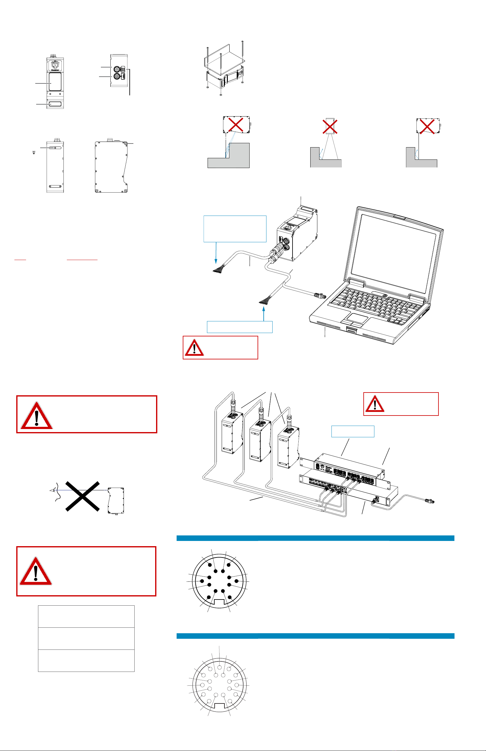
Side mount (shown): Use three 5 mm bolts of appropriate length.
Top mount: Use three or five M4 screws of suitable length (model-
dependant). Recommended thread engagement into the housing is 4.7 mm.
Do not occlude camera’s view of the laser
Do not install near surfaces that might
create unexpected laser reflections
2. CONNECTING GOCATOR TO A HOST COMPUTER
1. MOUNTING
USER PC
(can be disconnected after setup)
GOCATOR POWER AND
ETHERNET CORDSET
Power: 24-48VDC @ 15W
Laser Safety: +24-48VDC to enable
Wire rich I/O
as required by application
ex. Serial / Trigger Input /
Encoder / Photocell / etc.
GOCATOR I/O
CORDSET
GOCATOR
Standalone System
GOCATORS
POWER, LASER SAFETY,
TRIGGER INPUTS, ENCODER
MASTER 810/2410
GIGABIT ETHERNET SWITCH
TO PC
(can be disconnected
after setup)
GOCATOR
POWER AND
ETHERNET CORDSETS
Dual / Multi-Sensor System
GOCATOR OVERVIEW
Each sensor model in the Gocator 2600 series is designed with a
unique Clearance Distance (CD), Measurement Range (MR) and
Field of View (FOV). Models have dierent numbers of mounting
holes. Refer to the user manual for more information about your
model.
GROUNDING GOCATOR
Gocator housings should be grounded to the earth and the
grounding shield of the Gocator I/O cordsets. Gocator
sensors are designed to provide adequate grounding through
the M4 screws. Always check grounding with a multi-meter to
ensure electrical continuity between the mounting frame and
the Gocator connectors.
The frame or electrical cabinet that the Gocator is mounted to
must be connected to earth ground.
NOTE: Mounting the Gocator is recommended before applying power. Ensure that a proper earth ground is es-
tablished and that a heat sink is properly installed before applying power.
Camera
Laser
Emitter
Side
Mounting
Holes
3x Ø 5
Power/LAN
I/O
LED Indicators
When starting the Gocator,
the Power indicator and the
Laser indicator (if safety is en-
abled) should light. If not, refer to
the troubleshooting table below
or the user manual.
Always power down sensor
before removing cables
from the sensor
Leave protective caps on any
connectors that are not used.
ELECTRICAL SAFETY
Minimize voltage potential between system ground (ground
reference for I/O signals) and sensor ground
Use shielded cables with shield grounded at both ends. Sen-
sor housing should be connected to earth ground.
Use a suitable power supply
The +24-48V power supply used with Gocator 2600 sensors
should be an isolated supply with inrush current protection.
Use care when handling powered devices
Wires connecting to the sensor should not be handled while
the sensor is powered. Doing so may cause electrical shock to
the user or damage to the equipment.
Laser Sensor
WARNING: DO NOT LOOK DIRECTLY
INTO THE LASER BEAM
GROUNDING CORDSET (RECOMMENDED)
To minimize interference with other equipment, the Power &
Ethernet or the Power & Ethernet to Master cordset (depend-
ing on cordset used in system) can be grounded by termi-
nating the cordset shield before the split. The most eective
grounding method is to use a 360-degree clamp. For instruc-
tions, see the user manual.
LASER SAFETY
The full laser safety details including precautions,
responsibilities and requirements are stated in the Gocator
user manual. Use of controls or adjustments or performing
procedures other than those specified in the user manual may
result in hazardous radiation exposure.
The light emitted from these devices has been set in ac-
cordance with IEC60825. However, staring into the beam,
whether directly or indirectly, must be avoided. IEC60825
classifies laser products into three dierent categories de-
pending on light emitted, wavelength and eye safety.
This product is designated for use solely as a component
and as such it does not fully comply with the standards relat-
ing to laser products specified in U.S. FDA CFR Title 21 part
1040 and IEC 60825-1.
Failure to adhere to the guidelines described
in this section may result in electrical shock
or equipment damage.
Top Mounting
Holes
3x M4 4.7
Connector Pin Details
C
J
TN
L
M
A
U
P
R
S
G
O
E
Power/LAN Pin Function Conductor Color (Standard) Conductor Color (High Flex)
LGND_24-48V White/Orange & Black Orange/Red
LGND_24-48V Orange/Black Orange/Black
ADC_24-48V White/Green & Black Green/Red
ADC_24-48V Green/Black Green/Black
GSafety- White/Blue & Black Blue/Black
JSafety+ Blue/Black Blue/Red
ESync+* White/Brown & Black Brown/Red
C Sync-* Brown/Black Brown/Black
M Ethernet MX1+ White/Orange White/Orange
N Ethernet MX1- Orange Orange
O Ethernet MX2+ White/Green White/Green
P Ethernet MX2- Green Green
S Ethernet MX3- White/Blue White/Blue
REthernet MX3+ Blue Blue
T Ethernet MX4+ White/Brown White/Brown
U Ethernet MX4- Brown Brown
* The Sync leads are not connected in the open wire versions of the Power/LAN cordsets.
View: Looking into the
connector on the sensor.
I C
B
N
M
A
K
U
L
T
RP
O
D
E
F
S
G
H
I/O Pin Function Conductor Color (Standard) Conductor Color (High Flex)
D Trigger_in+ Grey Blue/Red
H Trigger_in- Pink Blue/Black
N Out_1+ (Digital Output 0) Red Brown/Red
O Out_1- (Digital Output 0) Blue Brown/Black
S Out_2+ (Digital Output 1) Ta n Green/Red
T Out_2- (Digital Output 1) Orange Green/Black
M Encoder_A+ White/Brown & Black Pink/Red
U Encoder_A- Brown/Black Pink/Black
I Encoder_B+ Black Yellow/Red
K Encoder_B- Violet Yellow/Black
A Encoder_Z+ White/Green & Black White/Red
L Encoder_Z- Green/Black White/Black
B Serial_out+ White Purple/Red
C Serial_out- Brown Purple/Black
E Reserved Blue/Black Red
G Reserved White/Blue & Black Black
P Reserved Green Gray/Red
F Reserved Yellow & Maroon/White Gray/Black & Orange/Black
R Reserved Maroon (not connected) Orange/Red (not connected)
View: Looking into the
connector on the sensor.
CLASS 2 LASER PRODUCT
LASER RADIATION
DO NOT STARE INTO THE BEAM
CLASS 3R LASER PRODUCT
LASER RADIATION
AVOID DIRECT EYE EXPOSURE
CLASS 3B LASER PRODUCT
LASER RADIATION
AVOID EXPOSURE TO THE BEAM

Other LMI Technologies Accessories manuals

LMI Technologies Gocator 2300 Series User manual

LMI Technologies

LMI Technologies Gocator 2300 Series User manual

LMI Technologies DynaVision S Series User manual

LMI Technologies

LMI Technologies DynaVision S Series User manual

LMI Technologies Gocator 2320 User manual

LMI Technologies

LMI Technologies Gocator 2320 User manual

LMI Technologies LCI401 User manual

LMI Technologies

LMI Technologies LCI401 User manual

LMI Technologies Gocator 2000 User manual

LMI Technologies

LMI Technologies Gocator 2000 User manual

LMI Technologies Gocator 2130 User manual

LMI Technologies

LMI Technologies Gocator 2130 User manual

LMI Technologies Gocator 2540 User manual

LMI Technologies

LMI Technologies Gocator 2540 User manual

LMI Technologies Dynavision SPR-04 User manual

LMI Technologies

LMI Technologies Dynavision SPR-04 User manual

LMI Technologies 2020 User manual

LMI Technologies

LMI Technologies 2020 User manual

LMI Technologies Gocator 2100 Series User manual

LMI Technologies

LMI Technologies Gocator 2100 Series User manual

LMI Technologies Dynavision L1 User manual

LMI Technologies

LMI Technologies Dynavision L1 User manual

LMI Technologies Gocator 2500 Series User manual

LMI Technologies

LMI Technologies Gocator 2500 Series User manual

LMI Technologies Gocator 2100 Series User manual

LMI Technologies

LMI Technologies Gocator 2100 Series User manual

LMI Technologies Gocator 3210 User manual

LMI Technologies

LMI Technologies Gocator 3210 User manual

LMI Technologies LCI1220 User manual

LMI Technologies

LMI Technologies LCI1220 User manual

Popular Accessories manuals by other brands

YUNEEC E- GO quick start guide

YUNEEC

YUNEEC E- GO quick start guide

Retractable Awnings KONYA installation instructions

Retractable Awnings

Retractable Awnings KONYA installation instructions

Datalogic S80-MH-5-YL09 instruction manual

Datalogic

Datalogic S80-MH-5-YL09 instruction manual

Aroma Outfitters RA-25 Operating and user guide

Aroma Outfitters

Aroma Outfitters RA-25 Operating and user guide

Wenglor P1NK Series operating instructions

Wenglor

Wenglor P1NK Series operating instructions

Brinsea Ovation 56 ECO operating manual

Brinsea

Brinsea Ovation 56 ECO operating manual

Insignia NS-MB4000B-C quick start guide

Insignia

Insignia NS-MB4000B-C quick start guide

Parker Pneumatic MPS-1 Series Installation & service instructions

Parker Pneumatic

Parker Pneumatic MPS-1 Series Installation & service instructions

Petasense Vibration mote 3 user manual

Petasense

Petasense Vibration mote 3 user manual

Simrad PI DEPTH - MANUAL 2 instruction manual

Simrad

Simrad PI DEPTH - MANUAL 2 instruction manual

Panasonic MAZWxxxH Series Specification sheet

Panasonic

Panasonic MAZWxxxH Series Specification sheet

SICK SureSense HTB18L Series operating instructions

SICK

SICK SureSense HTB18L Series operating instructions

Euroscreen Thor manual

Euroscreen

Euroscreen Thor manual

Waeco CoolFun CK40D Hybrid instruction manual

Waeco

Waeco CoolFun CK40D Hybrid instruction manual

Automation Technology C5 Series user manual

Automation Technology

Automation Technology C5 Series user manual

Aotoro ED45 Series instruction manual

Aotoro

Aotoro ED45 Series instruction manual

Air Creation IXess 13 Maintenance manual

Air Creation

Air Creation IXess 13 Maintenance manual

LEGRAND neat PIR II user manual

LEGRAND

LEGRAND neat PIR II user manual

manuals.online logo
manuals.online logoBrands
  • About & Mission
  • Contact us
  • Privacy Policy
  • Terms and Conditions

Copyright 2025 Manuals.Online. All Rights Reserved.