LMI Technologies Dynavision SPR-04 User manual

Copyright LMI Technologies Inc.
Version B 1
SPR-04
Intelligent
Single Point Sensor
USER MANUAL
by LMI Technologies Inc.

Copyright LMI Technologies Inc.
Version B
2
LMI Technologies Inc.
1673 Cliveden Ave.
Delta, BC V3M 6V5
Telephone: (604) 636-1011
Fax: (604) 516-8368
www.lmint.com
Trademarks and Restrictions
DynaVisionis a registered trademark of LMI Technologies Inc.
This product is designated for use solely as a component and as such it does not comply with the standards
relating to laser products specified in U.S. FDA CFR Title 21 Part 1040.
Windows 98, and Windows NT, Windows XP®are registered trademarks of Microsoft Corporation.
No part of this publication may be copied, photocopied, reproduced, transmitted, transcribed, or reduced to any
electronic medium or machine readable form without prior written consent of LMI Technologies Inc.
This product is covered under one or more of the following patents:
USA: 5,096.922 4375,921 4,305.661 4,373.804 4,875.776
5,114.230 5,164.579 5,362.970 5,510.625 5,670.787
5,684.292 5,691.545 5,734.172 4,667.231 4,576.482
4,394.683 5,811.827 Australia 616.731
Canada 1,307.051 1,116.750 New Zealand 228.128
Germany 30 16 361 31 23 703 Finland 94551
Printed in Canada
Version B

TABLE OF CONTENTS
Copyright LMI Technologies Inc.
Version B iii
1. SPECIFICATIONS 5
1.1 WELCOME TO THE SPR-04 5
1.1.2HOW DO LASER TRIANGULATION SENSORS WORK BEST? 5
1.1.3MECHANICAL SPECIFICATIONS 5
ELECTRICAL SPECIFICATIONS 7
1.1.4.1. ENVIRONMENTAL SPECIFICATIONS 7
1.1.4.2. LASER SPECIFICATIONS 7
1.1.4.3. PERFORMANCE SPECIFICATIONS 7
1. LASER SAFETY 8
2.1 OEM SAFETY RESPONSIBILITIES 8
2.1.1 LASER WARNING SIGN FORMAT 8
2.1.2 LASER EMISSION WARNING INDICATORS 9
2.1.3 BEAM ATTENUATORS 9
2.1.4 ADDITIONAL REQUIREMENTS FOR CLASS IIIB SENSORS 9
2.1.5 POWER-ON DELAYS 9
2.1.6 KEY LOCK SWITCH 9
2.1.7 REMOTE INTERLOCK CONNECTOR 9
3. INTRODUCTION 10
3.1 HOW CAN THE SPR-04 BE USED? 10
3.1.1 DO INEED A COMPUTER TO USE THE SPR-04? 10
3.2 UNPACKING 10
3.3 GETTING STARTED 10
3.3.1 NECESSARY EQUIPMENT 10
3.3.2 CONNECTOR PIN OUT (AS VIEWED FROM THE SENSOR) 11
3.3.3 OPERATING YOUR SPR-04 SENSOR IS QUITE SIMPLE. 11
3.4. MECHANICAL MOUNTING 12
3.5. SENSOR ORIENTATION 14
4. SERIAL COMMUNICATIONS 15
4.1 GENERAL OVERVIEW 15
4.2 COMMUNICATIONS SPECIFICATIONS 15
4.3 SERIAL SPECIFICATION 15
4.4 SERIAL CONNECTIONS MULTI-DROP CONFIGURATIONS 16
4.5 USING SP SETUP UTILITY 17
4.5.1. CONNECTING TO THE SENSOR 17
4.5.2. CONNECTING SUCCESSFULLY TO THE SPR-04 SENSOR 18
4.5.3. CHANGING SENSOR PARAMETERS 19
4.5.4. SENSOR SETTINGS/DIAGNOSTIC 21
5. COMMUNICATIONS PROTOCOL 25
5.1 GENERAL PACKET PROTOCOL 25
5.2 PACKET DESCRIPTION 25
NUMERIC FORMATS 26

TABLE OF CONTENTS
Copyright LMI Technologies Inc.
Version B
iv
5.6 COMMUNICATIONS ERROR HANDLING 38
5.6.1 HOW DO IPROCESS A RECEIVED DATA PACKET? 38
5.6.3 WHAT IF THE SENSOR DETECTS AN ERROR? 38
5.7 PACKET TIMING 38
5.7.1 WHAT IF TRANSMISSION TIME BETWEEN 2BYTES EXCEEDS 50 MS? 38
5.7.3 HOW DO IMAKE SURE THE HOST AND SENSOR ARE SYNCHRONIZED? 38
6. APPLICATION PROGRAM DEVELOPMENT 39
6.1 PSEUDO CODE 39
7. ANALOG OUTPUT 42
8. TROUBLESHOOTING 45
8.1 LASER IS OFF 45
8.3 NO DATA COMES FROM SENSOR’S ANALOG OUTPUT. 45
8.4 IN A MULTI-DROP CONFIGURATION, 46
8.5 DATA APPEARS ERRATIC OR JUMPY 46
8.6 DATA IS NOT AS ACCURATE AS EXPECTED 46
9.0 MAINTENANCE 46
10. GETTING FURTHER HELP 47
10.1 LIST OF AGENTS 47
10.1.1 CANADA AND THE UNITED STATES 47

SPECIFICATIONS
Copyright LMI Technologies Inc.
Version B 5
1. Specifications
1.1 Welcome to the SPR-04
The SPR-04 is a member of the DynaVisionfamily of laser-based ranging sensors from LMI Technologies Inc. These
sensors employ a laser and the triangulation principle to make precise measurements of range.
Object at Position ‘A’
Object at Position ‘B’
Laser Beam
LASER
As the distance from the
sensor to the object changes,
the light from the object is
detected at a different pixel
on the CCD array.
CCD Array
Lens
Object ‘B’Detected hereObject ‘A’Detected here
SPR04
Sensor
Triangulation Principle
The distance from the face of the sensor to the sensor's zero point is the Standoff range. The sensor cannot make any
measurements closer than the Standoff range. If a target is placed closer than the zero point, the analog output reads zero
volts and the digital output will return “Out of Range”indicating out of range.
The distance from the sensor's zero point to the sensor's maximum point (for which it has been calibrated) is the Range.
In between these two points the sensor will return a valid reading indicating how far the measurement surface is away
from the standoff, or zero point.
1.1.1 What is the maximum distance an object can be placed from the sensor's reference point?
The Standoff distance plus the Range distance is the maximum distance an object can be placed away from the face of
the sensor.
Standoff distance + Range distance = Object’s Maximum Distance
If the distance to an object is greater than the Standoff distance plus the Range distance, the sensors analog output will
read zero volts and the digital output will return “Out of Range”indicating out of range.
Object Distance > (Standoff + Range) => Out of Range
1.1.2 How do laser triangulation sensors work best?
Laser triangulation sensors work best when the measurement surface is a diffuse reflector such as the surface of a piece of
paper, wood, or non-shiny metal and plastic.
1.1.3 Mechanical Specifications
Dimensions 6.00" x 3.06" x 1.64"

SPECIFICATIONS
Copyright LMI Technologies Inc.
Version B
6
2.307"
5.000"
0.957"
1.638"
1.530"
3.060"
2.780"
0.500"
5.500"
5.750"
6.000"
0.250"
0.691"
3.400"
0.125"
4.250"
0.280"

SPECIFICATIONS
Copyright LMI Technologies Inc.
Version B 7
Electrical Specifications
Power Supply
Voltage
15 VDC - 30 VDC (300mA minimum @
15VDC)
Analog Output
0 VDC –10 VDC, 4 - 20mA
Maximum
Analog Output
Load
5k
1.1.4.1. Environmental Specifications
Ambient Temperature Operating min 0° C ( 32° F)
max +50° C (122° F)
Storage
min -30° C (-22° F)
max +70° C (158° F)
Relative Humidity 95% Maximum Non-Condensing at 40° C (104° F)
Housing Gasket aluminum enclosure
1.1.4.2. Laser Specifications
Class IIIb
Laser Visible
Wave Length 655 nm
Laser Power < 7 mW
1.1.4.3. Performance Specifications
Accuracy +/- 0.005inches (+/- 0.127mm)
Resolution (Digital): 0.001 inches (0.025mm)
Resolution (Analog): 0.003 inches (0.075mm)
Standoff 2" (50mm for metric)
Max Range 8" (200mm for metric)

LASER SAFETY
Copyright LMI Technologies Inc.
Version B
8
1. Laser Safety
Caution! Use of controls or adjustments, or performance of procedures other than those specified herein may result in
hazardous radiation exposure.
DynaVisionscanners use lasers to illuminate the measurement surface. This requires that specific safety precautions be
taken when working near, or servicing the sensors.
Under the Code of Federal Regulations (CFR) 21, Part 1040, the U.S. Food and Drug Administration (FDA), classifies
the SPR-04 sensor as a Class IIIb device. This classification is clearly marked on the SPR-04 sensor.
Laser
Laser
Sensor
WARNING: DO NOT look directly
into the laser beam
Warning! The SPR-04 is a Class IIIb laser device. Regardless of the power rating, or whether or not the laser is
visible, the laser should not be viewed directly, or through a mirror, as it may result in damage to the
eyes
2.1 OEM Safety Responsibilities
LMI Technologies Inc. has filed a report with the US Food and Drug Administration (FDA) to assist OEM's in achieving
certification of their own applications by referencing the report accession number. The following paragraphs outline
areas that are not covered by LMI Technologies Inc. submission and need to be specifically addressed by the OEM.
2.1.1 Laser Warning Sign Format
Laser warning signs must be located in the vicinity of the sensors such that they will be readily observed. Refer to the
following diagram for an example of the laser warning sign. Different warning signs are required for different laser
classifications. These are specified in the CFR Title 21, Section 1040. An example is shown below for a Class IIIb
sensor.
DANGER
INVISIBLE AND/OR VISIBLE LASER RADIATION
AVOID DIRECT EXPOSURE TO BEAM
PEAK POWER 50mW
WAVELENGTH 600-780nm
CLASS IIIB LASER PRODUCT

LASER SAFETY
Copyright LMI Technologies Inc.
Version B 9
2.1.2 Laser Emission Warning Indicators
As specified by the US Food and Drug Administration, Department of Health and Human Services, Code of
Federal Regulations 21 Section 1040 (CFR 21-1040), the controls which operate the single point sensors must
incorporate a visible or audible signal when the lasers of the sensors are active. Typically this consists of a
warning lamp which is illuminated when power is supplied to the sensor.
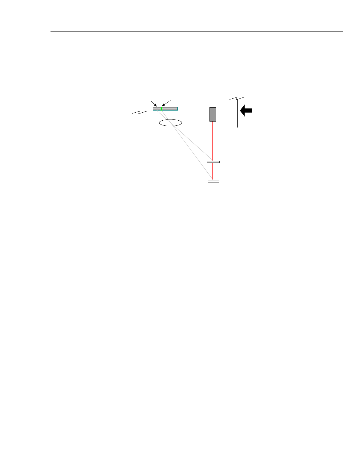
If the sensors are mounted more than 2 meters from each other, or the controls, it is required that warning
indicators be placed at each location. When mounting the warning indicator it is important not to mount it in a
location that would require exposure to the laser emissions in order to see it.
Additionally, CFR21-1040 standards require that he indicator be clearly visible through protective eyewear
designed specifically for the wavelengths of the emitted laser radiation.
2.1.3 Beam Attenuators
CFR 21-1040 standards specify that a permanently attached method of preventing human access to the laser
radiation other than switches, power connectors, or key control must be employed.
2.1.4 Additional Requirements for Class
IIIb sensors
All Class III laser sensors must adhere to the items mentioned in the preceding paragraphs. For any systems
which incorporate Class IIIb sensors (5mW or non-visible lasers) the following paragraphs describe additional
requirements that must be met.
2.1.5 Power-On Delays
A delay circuit is required for Class IIIb laser systems which illuminates the warning indicators, or sounds the
audible alarms for a short period of time prior to supplying power to the lasers. The length of the delay should
provide enough time to for personnel to take the appropriate action to avoid exposure to the lasers.
2.1.6 Key Lock Switch
The controls must have a key lock switch, which when in the OFF position prevents any power from being
supplied to the lasers. Additionally, the switch must not allow the key to be removed from the lock while in the
ON position.
2.1.7 Remote Interlock Connector
A remote interlock connection that allows remote switches to be attached "in series" with the key lock switch on
the controls must be present. The deactivation of any remote switches must prevent power from being supplied
to the lasers.
None of the items mentioned above are supplied with the SPR-04 and are the
responsibility of the OEM to supply when incorporating the SPR-04 into their system or product.

INTRODUCTION &INSTALLATION
Copyright LMI Technologies Inc.
Version B
10
3. Introduction
3.1 How can the SPR-04 be used?
The SPR-04 can be used in a wide variety of measurement applications, including:
Object profiling
Thickness measurement
Parts inspection
Object alignment
Range measurement
The SPR-04 is a ‘smart’sensor incorporating an internal processor to handle calibration, scaling and data
conversion. The SPR-04 provides two analog output (0-10 VDC and 4-20mA) and digital serial output (RS-485).
3.1.1 Do I need a computer to use the
SPR-04?
An SPR-04 with the digital interface can be used with or without a computer control system.
Without a computer The SPR-04 can be employed as an analog sensor and does not require
connection to an external computer. Connect the cable to:
A suitable power supply
A voltage measurement device
With a computer The SPR-04 can be used in a computer-based data acquisition or control system.
Commands requesting data are sent to the sensor and the sensor responds by
providing range values. Commands and data are exchanged with the SPR-04
using a simple serial protocol (see Communications Protocol). To operate the
sensor:
3.2 UNPACKING
Upon receipt, unpack and visually inspect the sensor. The sensor is a single metal enclosure with a connector on
one side, and with laser and sensor viewing window on the opposite side. Ensure there is no damage to the
enclosure, connector or view windows.
The enclosed diskette contains:
SPR-04 Utility Program (SPUTIL.EXE)
3.3 GETTING STARTED
3.3.1 Necessary Equipment
You will need:
a DC power supply
an instrument capable of measuring zero (0) to ten (10) volts DC
a flat surface
Windows 98 or Windows XP (if you are using the sensor with a computer)
an RS-232 to RS-485 converter

INTRODUCTION &INSTALLATION
Copyright LMI Technologies Inc.
Version B 11
3.3.2 Connector Pin out (As viewed from the sensor)
1
6
15
Pin #1, 15 Power In (15 –30VDC)
Pin #2 Receive (-)
Pin #3 Transmit (-)
Pin #4 Analog Out 0 –10VDC
Pin #5 Out of Range Indicator
Pin #6 NC
Pin #7 NC
Pin #8 Analog Common
Pin #9 Receive (+)
Pin #10 Transmit (+)
Pin #11 Power Common
Pin #12 Analog out 4-20mA
Pin #13 OUT2B
Pin #14 NC
3.3.3 Operating your SPR-04 sensor is
quite simple.
You can use it in two ways
As a stand-alone device requiring only a DC power supply and an instrument capable of measuring zero (0) to
ten (10) volts DC.
Sensors with the optional digital serial interface can be connected to a personal computer through the serial
communication port.
1. Place the sensor onto a table or flat surface. Be sure that the pathway between the laser window (the round hole)
and the camera (the elongated window) is not obstructed.
2. Connect the enclosed cable to:
a suitable power supply
a voltage measurement device (e.g. a DVM)
Be sure that the power is OFF on the supply powering the SPR-04,
then connect the cable to the back of the SPR-04
3. Turn on your voltage measurement device.
4. If you are using a computer connect the enclosed cable to the serial port of the computer
The SPR-04 can be connected to both a computer and a voltage-measuring device at the same time.
5. Do not look directly into the laser output window nor point it in the direction of another person (see Laser
Safety).
6. Place a suitable target (e.g. a cardboard box or wood block) within the measurement range of the SPR-04

INTRODUCTION &INSTALLATION
Copyright LMI Technologies Inc.
Version B
12
7. Turn on the power supply to the SPR-04. The SPR-04 does not have a power switch so turning on the power
supply will activate the SPR-04.
8. If you are using a computer start the SPUtil.EXE application.
Set the software to use the correct communication port (See SPR-04 setup utility). Click on "View " to open the
range and spot information dialog. Click on "Start."
9. You should now see a voltage reading on the voltage measurement device, and/or a display of the range readings
on the computer screen.
You are now ready to employ the SPR-04 in a wide variety of applications.
3.4. Mechanical Mounting
The accuracy of the sensor is dependent on a secure mechanical mounting. Any movement or vibration of the
sensor relative to the object being measured will result in measurement errors. The sensor enclosure contains a
mounting plate with three pre-drilled mounting holes (See Figure Below).
Calibration of the SPR-04 is relative to the reference face of the sensor. The minimum distance the target can be
from the reference face of the sensor is the standoff distance.

INTRODUCTION &INSTALLATION
Copyright LMI Technologies Inc.
Version B 13
The surface the sensor is mounted to must be flat within 0.030”(0.76mm) between the three mounting points.
This can be accomplished with 0.125”(3.16mm) standoff washers between the mounting surface and the sensor.
To ensure that the sensor does not report a false reading, it is recommended that a baffle plate be used.
A baffle plate is a solid plate located outside the sensor's measurement range, directly in the sensor's field of
view. There needs to be a 3/8" hole drilled in the plate to allow the laser light to pass through. When there is no
target in the measurement range of the sensor the baffle plate will block the sensor's camera from seeing the laser
light. Therefore guaranteeing a fast response to the target coming into range and going out of range.

INTRODUCTION &INSTALLATION
Copyright LMI Technologies Inc.
Version B
14
3.5. Sensor Orientation
The sensor should be mounted so the beam is projected perpendicular to the surface.
The surface directly below the sensor should be non-reflective. If material is to move past the sensor, the sensor
should be mounted so that the movement of the material intersects the line between the laser and the camera.
CORRECT
AVOID EXPOSURE
from this aperture
Laser radiation is emitted
INCORRECT
Material Flow
CLASS IIIb LASER PRODUCT
DANGER
PEAK POWER 50m W
WAVELENGTH 600-780nM
INVISIBLE AND/OR VISIBLE LASER RADIATION
AVOIDDIRECT EXPOSURE TO BEAM
Material Flow

SERIAL COMMUNICATION COMMANDS
Copyright LMI Technologies Inc.
Version B 15
4. Serial Communications
4.1 General Overview
All communication between the host computer and the sensor is via an RS-485 serial interface.
All commands are initiated from the host computer to the sensor, with the sensor responding to the commands.
4.2 Communications Specifications
The SPR-04 uses the RS-422/485 standard for its serial communication. This is a differential driver/receiver
pair. It is capable of transmitting up to 4000 feet.
The serial ports of most personal computers are based on the two-wire RS-232 standard. To use a personal
computer as the host for a multi-drop configuration, you will need an RS-232 to RS-485 converter box.
The RS-485 option allows the sensor to be used in multi-drop configurations. This means that up to 32 units can
be connected to the same serial line. Each device must have a different address so that you are able to
distinguish which unit you are talking to. The utility SPUtil.EXE is supplied to allow you to set the address of
each SPR-04 unit. This program only works in Microsoft Windows® environments.
4.3 Serial Specification
Transmit and Receive lines are connected to the serial I/O port of a host computer. This serial I/O port must be
configured as follows:
Asynchronous
9600 - 57600 baud.
8 Data Bits
One Stop Bit
No Parity

SERIAL COMMUNICATION COMMANDS
Copyright LMI Technologies Inc.
Version B
16
4.4 Serial Connections Multi-Drop Configurations
SPR-04 sensors can be wired in a multi-drop configuration. The serial communication must be wired as full duplex;
meaning four wires are required to complete the hardware connection as illustrated in the figure below:
120 ohm
120 ohm
TX-
TX
-
TX
+
RX+
RX
+
RX-
RX
-
Host
Computer
RS-485 to
RS-232
Adapter
TX+
1ST Sensor 2ND Sensor X Sensor
RS-232 port
TX
-
TX
+
RX
+RX
-TX
-
TX
+
RX
+RX
-
Up to 32 SPR-04 sensors can
be
multi-dropped as shown.
Tx+ of all the SPR-04 sensors are connected to the Rx+ of the Host
Tx- of all the SPR-04 sensors are connected to the Rx- of the Host
Rx+ of all the SPR-04 sensors are connected to the Tx+ of the Host
Rx- of all the SPR-04 sensors are connected to the Tx- of the Host
A 120 ohm termination resistor must be connected across the Tx+ and Tx- at the end farthest away from the host
computer, and the Rx+ and Rx- nearest the host computer.

SERIAL COMMUNICATION COMMANDS
Copyright LMI Technologies Inc.
Version B 17
4.5 Using SP Setup Utility
4.5.1. Connecting to the Sensor
Start the SPUtil.exe software: click on the “New”button or select the File”Connect”option.
Select the proper COM Port, Baud Rate (57600 - Factory Default Rate), the unit address and click on “OK”button. If the
unit address is not known, check the”Use global address”option.
NOTE : Do not use ”Use global address”option in multi-drop configuration. All sensors have default address of 1. In
case of multi-drop configuration, ensure that each sensor has been assigned a unique address before being placed on
single communication line.

SERIAL COMMUNICATION COMMANDS
Copyright LMI Technologies Inc.
Version B
18
4.5.2. Connecting Successfully to the SPR-04 Sensor
Serial #. The number shown here is the sensor’s serial number which is labeled on the side
of the sensor enclosure (Factory Programmed).
Firmware This is the firmware version of the sensor (Factory Programmed).
Model # This is the sensor’s model number (Factory Programmed).
FPGA This is the sensor’s FPGA version of the sensor (Factory Programmed).

SERIAL COMMUNICATION COMMANDS
Copyright LMI Technologies Inc.
Version B 19
4.5.3. Changing Sensor Parameters
Address The sensor address may range from 1 to 255, the maximum number of sensors that can be
placed on a multi-drop line. Each sensor must have a different address.
To change the address of the sensor, enter new address and click on “Address”button.
Note: When changing the address, only one sensor must be communicating with the host.
Baud Rate This is the sensor’s Baud Rate that it uses to communicate to the Host. To change Baud Rate
select the Baud Rate from the list and click on “Baud Rate”button. The Baud rate is preset at
the factory to 57600 Baud.
Error Checking Error checking method used by sensor to communicate with the Host:
Checksum (Default) or CRC.
To change select the method from the list and click on “Error Checking”button.
Set to Defaults Sets all sensor parameters to factory defaults.

SERIAL COMMUNICATION COMMANDS
Copyright LMI Technologies Inc.
Version B
20
Sensor Address The sensor address may range from 1 to 255, the maximum number of sensors that can be
placed on a single multi drop line. Each sensor must have a different address. To change the
address of the sensor, double click on the current address. New window will appeared, enter
new address and click on “OK”button.
Note: When changing the address, only one sensor must be communicating with the host.
Baud Rate This is the sensor’s Baud Rate that it uses to communicate to the Host. To change Baud Rate
of the sensor, double click on the current Baud Rate. New window will appeared select the
Baud Rate from the list and click on “OK”button. The available rates are 9600, 19200, 39400,
and 57600.
The factory default Baud Rate is 57600.
Table of contents
Other LMI Technologies Accessories manuals

LMI Technologies
LMI Technologies 2020 User manual

LMI Technologies
LMI Technologies Gocator 2100 Series User manual

LMI Technologies
LMI Technologies Gocator 3210 User manual

LMI Technologies
LMI Technologies Dynavision L1 User manual

LMI Technologies
LMI Technologies Gocator 2100 Series User manual

LMI Technologies
LMI Technologies LCI1220 User manual

LMI Technologies
LMI Technologies Gocator 2300 Series User manual

LMI Technologies
LMI Technologies Gocator 2130 User manual

LMI Technologies
LMI Technologies Gocator 2540 User manual

LMI Technologies
LMI Technologies Gocator 2000 User manual