manuals.online logo
Brands
  1. Home
  2. •
  3. Brands
  4. •
  5. Loewe
  6. •
  7. TV Accessories
  8. •
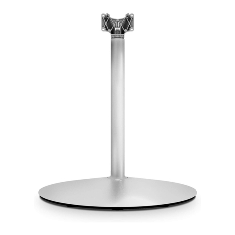
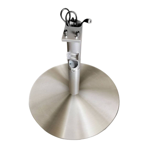
  9. Loewe Floor Stand Connect ID 32-46 User manual

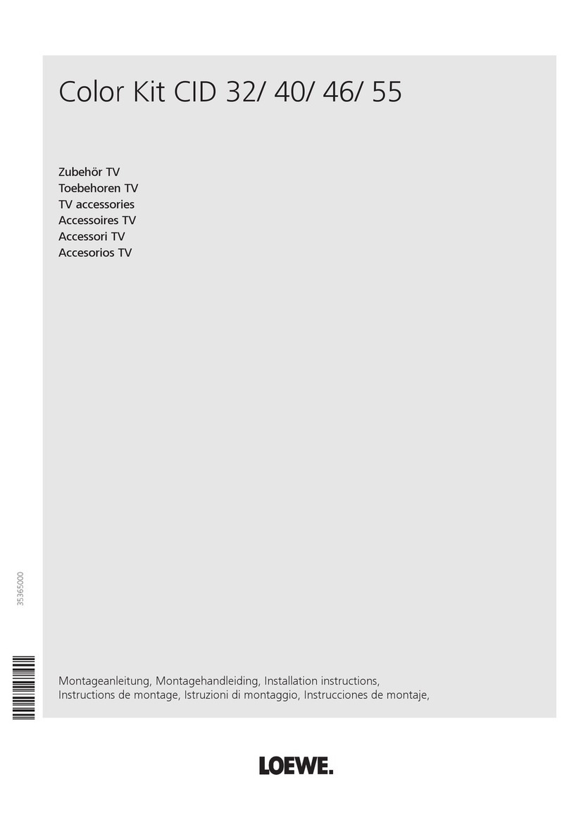
Loewe Floor Stand Connect ID 32-46 User manual

240–35185 000
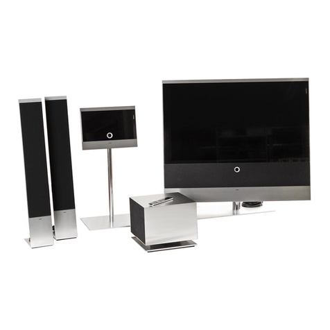
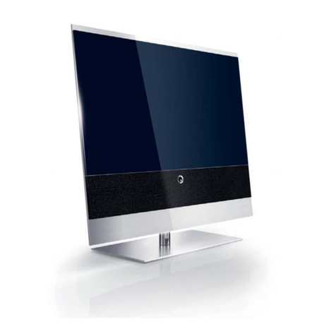
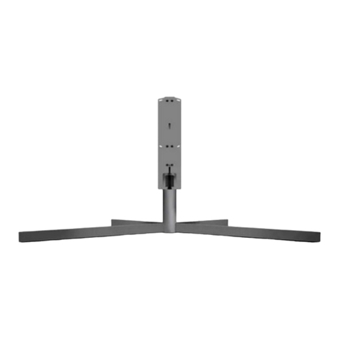
Floor Stand Connect ID 32-46
Equipment Board
Zubehör TV
Toebehoren TV
Accessories TV
Accessoires TV
Accessori TV
Accesorios TV
Montageanleitung, Montage-instructies, Installation instructions,
Instructions de montage, Istruzioni di montaggio, Instrucciones de montaje
35185_FloorStand_CID_20120306_Abgabeversion.indd 135185_FloorStand_CID_20120306_Abgabeversion.indd 1 20.03.2012 16:28:1220.03.2012 16:28:12
Floor Stand Connect ID 32-46
Art. Nr. 71333B00
Equipment Board Floor Stand Connect ID
Art. Nr. 71365T00
Edition 1, 02/12 CH
Printed in Germany
Änderungen vorbehalten
Wijzigingen voorbehouden
Subject to modifications
Modifications reservée
Con riserva di modifiche
Reservado el drecho a modificaciones
Deutschland
Loewe Opta GmbH
Customer Care Center
Industriestraße 11
D-96305 Kronach
D-96317 Kronach
Telefon 01801/22256393
Telefax (09261) 99500
35185_FloorStand_CID_20120306_Abgabeversion.indd 235185_FloorStand_CID_20120306_Abgabeversion.indd 2 20.03.2012 16:28:1320.03.2012 16:28:13
Volumen de suministro Floor Stand e
A Placa cobertora
B Placa base
C Tapa del cable (parte superior)
D Tapa del cable (parte posterior)
E 10 x tiras adhesivas
F 2x bridas de velcro (1 x premontada)
G Columnas
H Tapa Equipment Board
I 6x tornillos alomados M6x20, hexágono interior SW4
J 4x tornillos avellanados M4x6, Torx T20
K Llave Allen SW5 80x80
Advertencias de seguridad e
Respete las instrucciones del manual. Manipule
las herramientas con las precauciones necesarias.
Instale la combinación de aparatos de manera
que no presente riesgo de lesiones, p. ej., para
niños que estén jugando cerca, y de manera que
no pueda sufrir daños.
Por lo demás, las advertencias de seguridad de
nuestros televisores también tienen validez en
este caso.
Fornitura Floor Stand i
A Piastra di copertura
B Piastra a pavimento
C Copertura cavi (in alto)
D Copertura cavi (dietro)
E 10 x pezzi di nastro adesivo
F 2x fascette per cavi (1 x premontata)
G Colonnina
H Rivestimento consolle attrezzature
I 6x viti a testa bombata M6x20, esagono incassato SW4
J 4x viti a testa flangiata M4x6, testa torx T20
K Chiave esagonale SW5 80x80
Indicazioni di sicurezza i
Osservare le informazioni riportate nelle istruzioni.
Utilizzare gli attrezzi con la dovuta cautela.
Installare la combinazione di apparecchi in modo
tale che non possa essere danneggiata e che non
rappresenti un pericolo, ad esempio per i bambini
che giocano.
Anche in questo caso valgono le norme di sicu-
rezza relative ai nostri apparecchi TV.
Contenu de la livraison Floor Stand f
A Plaque de couverture
B Embase
C Cache du câble (supérieur)
D Cache du câble (arrière)
E 10 bandes adhésives
F 2 attache-câbles autoagrippants (1 prémonté)
G Pied
H Cache de l’Equipmentboard
I 6 vis à tête lentiforme M6x20, à six pans creux SW4
J 4 vis à tête bridée M4x6, Torx T20
K Clé à fourche SW5 80x80
Instructions de sécurité f
Veuillez observer les informations du mode d’em-
ploi. Soyez prudent lors de l’utilisation d’outils.
Positionnez votre combinaison d’appareils de telle
sorte qu’elle ne représente p. ex. aucun danger
pour des enfants en train de jouer et qu’elle ne
puisse pas être renversée.
Par ailleurs, les instructions de sécurité relatives à
nos téléviseurs sont également valables ici.
Scope of delivery of the floor stand g
A Cover plate
B Base plate
C Cable cover (above)
D Cable cover (behind)
E 10 x adhesive strips
F 2 x Velcro cable ties (1 x pre-attached)
G Column
H Cover for equipment board
I 6 x M6x20 pan head screws, SW4 hexagon socket
J 4 x M4x6 flange head screws, Torx T20
K SW5 hexagon socket Allen key 80 x 80
Safety instructions g
Observe the information in the instructions.
Handle tools with the necessary care and attention.
Install your combination of equipment in such a
way that it presents no danger to playing children
for example and also can not be damaged.
The safety instructions for our TV sets also apply
here.
Leveringsomvang Floor Stand l
A Afdekplaat
B Bodemplaat
C Kabelafdekking (boven)
D Kabelafdekking (achter)
E 10 x plakstroken
F 2x klittenband-kabelbinder (1 x voorgemonteerd)
G Zuil
H Afdekking equipmentboard
I 6x lenskopschroef M6x20, inbus SW4
J4xflenskopschroef M4x6, Torx T20
K Steeksleutel SW5 80x80
Veiligheidsvoorschriften l
Neem de aanwijzingen in de handleiding in acht.
Wees voorzichtig bij het werken met gereed-
schap. Stel de apparatuur zo op dat ze geen
gevaar vormt voor spelende kinderen en ook niet
kan worden beschadigd.
Verder gelden hier ook de veiligheidsvoorschriften
voor onze tv-toestellen.
Lieferumfang Floor Stand d
A Abdeckplatte
B Bodenplatte
C Kabelabdeckung (oben)
D Kabelabdeckung (hinten)
E 10 x Klebestreifen
F 2x Klett-Kabelbinder (1 x vormontiert)
G Säule
H Abdeckung Equipmentboard
I 6x Linsenkopfschraube M6x20, Innensechskant SW4
J 4x Flanschkopfschraube M4x6, Torx T20
K Sechskantschlüssel SW5 80x80
Sicherheitshinweise d
Beachten Sie die Informationen der Anleitung.
Lassen Sie im Umgang mit Werkzeug die nötige
Vorsicht walten. Stellen Sie Ihre Gerätekombinati-
on so auf, dass sie, z.B. für spielende Kinder keine
Gefährdung darstellt und auch nicht beschädigt
werden kann.
Des weiteren haben die Sicherheitshinweise für
unsere TV-Geräte auch hier Gültigkeit.
Floor Stand CID 32-46 / Equipment Board FS CID - 3 -
Montageanleitung Instructions de montage
Montage-instructies Istruzioni di montaggio
Installation instructions Instrucciones de montaje
A
B
E
F
I
J
K
D
C
H
G
35185_FloorStand_CID_20120306_Abgabeversion.indd 335185_FloorStand_CID_20120306_Abgabeversion.indd 3 20.03.2012 16:28:1320.03.2012 16:28:13
Montaje del Floor Stand e
e
Durante el montaje coloque una base protectora sobre
la placa cobertora (A). De esta forma evitará arañazos
en la superficie de aluminio.
1
Retirar la placa cobertora de la placa base
2
Pegar 10 tiras adhesivas (E) en la placa base.
Retirar la lámina de la cinta adhesiva.
3
Colocar la placa cobertora en la placa base con
cuidado, de forma que las perforaciones de las
placas coincidan.
¡No es posible realizar una corrección posterior!
4
Colocar la placa base en el borde de una mesa,
a continuación atornillar a mano la columna con
tornillos alomados (I)
Montaggio Floor Stand i
i
Durante l’intero montaggio, posizionare una base pro-
tettiva sulla piastra di copertura (A). In questo modo si
evita di graffiare la superficie in alluminio.
1
Rimuovere la piastra di copertura dalla piastra a
pavimento
2
Applicare 10 pezzi di nastro adesivo (E) sulla piastra
a pavimento.
Rimuovere la pellicola di supporto sulle strisce
adesive.
3
Posizionare con cautela la piastra di copertura sulla
piastra a pavimento in modo che i fori delle piastre
coincidano.
Non è possibile apportare delle modifiche in un
secondo tempo!
4
Collocare la piastra a pavimento all’angolo del
tavolo, poi avvitare saldamente la colonna con
Montage du Floor Stand f
f
Pendant toute l’opération de montage, placer un
support de protection sur la plaque de couverture (A).
Vous éviterez ainsi de rayer la surface en aluminium.
1
Retirer la plaque de couverture de l’embase
2
Coller 10 bandes adhésives (E) sur l’embase.
Enlever le film de la bande adhésive.
3
Placer méthodiquement la plaque de couverture sur
l’embase en faisant coïncider les trous de perçage
des plaques.
Un réajustement postérieur est impossible !
4
Poser l’embase sur le bord d’une table puis fixer
la colonne à la main, au moyen de vis à tête
lentiforme (I)
Installing the floor stand g
g
During the entire installation lay a protective underlay
on the cover plate (A). In this way you will avoid
scratching the aluminium surface.
1
Remove the cover plate from the base plate
2
Stick 10 adhesive strips (E) on the base plate.
Remove backing film on the adhesive tape.
3
Carefully place the cover plate on the base plate in such
a way that the holes of the plates lie over each other.
It is not possible to correct the position afterwards!
4
Lay the base plate on one edge of the table, then screw
the column hand tight with the pan head screws (I)
Floor Stand monteren l
l
Plaats tijdens de montage een bescherming op de af-
dekplaat (A). Zo voorkomt u krassen op het aluminium
oppervlak.
1
Afdekplaat van de bodemplaat afnemen
2
10 plakstroken (E) op de bodemplaat plakken.
Beschermfolie van de plakstrook verwijderen.
3
Afdekplaat zorgvuldig op de bodemplaat plaatsen,
zodat de gaten van de platen over elkaar vallen.
Correctie naderhand is niet mogelijk!
4
Bodemplaat op een tafelrand leggen, dan de zuil
met de lenskopschroeven (I) handvast vastschroeven
Floor Stand montieren d
d
Legen Sie während der gesamten Montage eine
schützende Unterlage auf die Abdeckplatte (A). So ver-
hindern Sie ein Verkratzen der Aluminumoberfläche.
1
Abdeckplatte (A) von Bodenplatte (B) abnehmen
2
10 Klebestreifen (E) auf Bodenplatte aufkleben.
Trägerfolie auf den Klebestreifen entfernen.
3
Abdeckplatte auf Bodenplatte sorgfältig aufsetzen,
dass die Bohrungen der Platten übereinander sind.
Eine nachträgliche Korrektur ist nicht möglich!
4
Bodenplatte an eine Tischkante legen, dann Säule
mit Linsenkopfschrauben (I) handfest anschrauben
Floor Stand CID 32-46 / Equipment Board FS CID - 4 -
Montageanleitung Instructions de montage
Montage-instructies Istruzioni di montaggio
Installation instructions Instrucciones de montaje
A
B
1
E
23
I
4
35185_FloorStand_CID_20120306_Abgabeversion.indd 435185_FloorStand_CID_20120306_Abgabeversion.indd 4 20.03.2012 16:28:1320.03.2012 16:28:13
Volumen de suministro del
Equipment Board opcional e
L Equipment Board (capacidad de carga: máx. 10 kg)
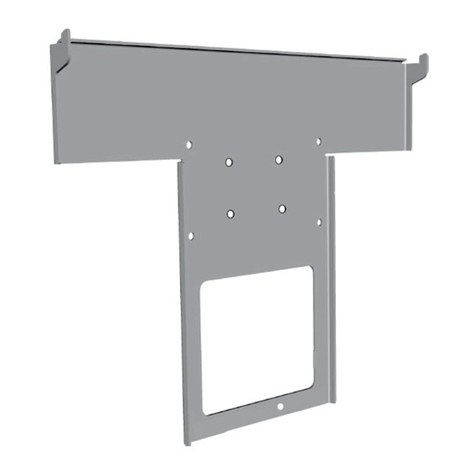
M Soporte
N 2x tornillos avellanados M5x16, hexágono interior SW3
O 2x tornillos alomados M6x18, hexágono interior SW4
P 2x arandelas de contacto
Fornitura dell‘accessorio opzionale
Equipment Board i
L Equipment Board (portata: max.10 kg)
M Supporto
N 2x viti a testa svasata M5x16, esagono incassato SW3
O 2x viti a testa bombata M6x18, esagono incassato SW4
P 2x rondelle di contatto
Contenu de la livraison de
l‘Equipment Board en option f
L Equipment Board (capacité de charge max. 10 kg)
M Support
N 2 vis noyées M5x16, à six pans creux SW3
O 2 vis à tête lentiforme M6x18, à six pans creux SW4
P 2 rondelles de contact
Scope of delivery of the optional
equipment board g
L Equipment board (load bearing capacity: max 10 kg)
M Holder
N 2 x M5x16 countersunk screws, SW3 hexagon socket
O 2 x M6x18 pan head screws, SW4 hexagon socket
P 2 x contact washers
Leveringsomvang van de optionele
Equipment Board l
L Equipment Board (draagkracht: max.10 kg)
M Houder
N 2x parkerschroef M5x16, inbus SW3
O 2x lenskopschroef M6x18, inbus SW4
P 2x contactplaatjes
Lieferumfang des optionalen
Equipment Board d
L Equipment Board (Tragfähigkeit: max.10 kg)
M Halter
N 2x Senkkopfschraube M5x16, Innensechskant SW3
O 2x Linsenkopfschraube M6x18, Innensechskant SW4
P 2x Kontaktscheiben
Floor Stand CID 32-46 / Equipment Board FS CID - 5 -
Montageanleitung Instructions de montage
Montage-instructies Istruzioni di montaggio
Installation instructions Instrucciones de montaje
L M N
O
P
35185_FloorStand_CID_20120306_Abgabeversion.indd 535185_FloorStand_CID_20120306_Abgabeversion.indd 5 20.03.2012 16:28:1420.03.2012 16:28:14
Fijación del Equipment Board e
e
Descripción del montaje del Equipment Board opcio-
nal. ¡Para reequipar el Floor Stand con un Equipment
Board se deben retirar antes del montaje los cables
instalados en la columna!
Durante el montaje coloque una base protectora
sobre la placa cobertora. De esta forma evitará
arañazos en la superficie de aluminio.
1
Enroscar el soporte (M) con tornillos avellanados (N)
al Equipment Board (L).
2
Presionar y extraer la cubierta de los cables en la
columna del Floor Stand por el lado posterior hacia
delante
Fissaggio di Equipment Board i
i
Viene descritto il montaggio dell'accessorio opzio-
nale Equipment Board. In caso di una successiva
dotazione di Floor Stand con Equipment Board,
prima del montaggio è necessario rimuovere i cavi
collocati nella colonna!
Durante l'intero montaggio, posizionare una base
protettiva sulla piastra di copertura. In questo modo
si evita di graffiare la superficie in alluminio.
1
Avvitare il supporto (M) a Equipment Board (L) con
viti a testa svasata (N)
2
Estrarre il coperchio del vano cavi esercitando una pres-
sione dal lato posteriore dalla colonna di Floor Stand
Fixation de l‘Equipment Board f
f
Description du montage de l'Equipment Board en
option. En cas d'équipement postérieur du Floor
Stand avec un Equipment Board, les câbles posés sur
la colonne doivent être retirés avant le montage !
Pendant toute l'opération de montage, placer un
support de protection sur la plaque de couverture.
Vous éviterez ainsi de rayer la surface en aluminium.
1
Fixer le support (M) au moyen de vis noyées (N) sur
l'Equipement Board
2
Retirer le cache-câbles sur la partie avant de la colonne
du Floor Stand en le poussant de l'arrière vers l'avant
Fastening the equipment board g
g
The description is of the installation of the optional
equipment board. If the equipment board is retrofit-
ted to the floor stand, the cables laid on the column
must be removed before the board is installed.
During the entire installation lay a protective un-
derlay on the cover plate. In this way you will avoid
scratching the aluminium surface.
1
Screw the holder (M) to the equipment board (L)
with the countersunk screws (N)
2
Press the cable cover on the front of the floor stand
column out forwards from the rear
Equipment Board bevestigen l
l
Beschreven wordt de montage van de optionele Equip-
ment Board. Bij naderhand uitrusten van de Floor Stand
met een Equipment Board moeten voor de montage daar-
van, de in de zuil geïnstalleerde kabels worden verwijderd!
Plaats tijdens de montage een bescherming op de
afdekplaat. Zo voorkomt u krassen op het alumi-
nium oppervlak.
1
Houder (M) met schroeven (N) op het Equipment
Board (L) schroeven
2
Kabelafdekking voor op de zuil van de Floor Stand
vanaf de achterkant naar voren toe uitdrukken
Equipment Board befestigen d
d
Beschrieben wird die Montage des optionalen Equip-
ment Board. Bei Nachrüstung des Floor Stand mit
einem Equipment Board müssen vor dessen Montage
die an der Säule verlegten Kabel entfernt werden!
Legen Sie während der gesamten Montage eine
schützende Unterlage auf die Abdeckplatte. So ver-
hindern Sie ein Verkratzen der Aluminumoberfläche.
1
Halter (M) mit Senkkopfschrauben (N) am Equiment
Board (L) anschrauben
2
Kabelabdeckung vorne an der Säule des Floor Stand
von der Rückseite her nach vorne herausdrücken
Floor Stand CID 32-46 / Equipment Board FS CID - 6 -
Montageanleitung Instructions de montage
Montage-instructies Istruzioni di montaggio
Installation instructions Instrucciones de montaje
N
M
L
1
2
35185_FloorStand_CID_20120306_Abgabeversion.indd 635185_FloorStand_CID_20120306_Abgabeversion.indd 6 20.03.2012 16:28:1420.03.2012 16:28:14
e
3
Inclinar el Equipment Board hacia delante, hasta
que se pueda introducir el soporte a través de la
abertura rectangular. A continuación orientar el
Equipment Board horizontalmente y posicionar
hacia atrás hasta el tope.
4
Atornillar de soporte desde detrás a la columna
con las arandelas de contacto (P) y los tornillos
alomados (O).
5
Apretar los tornillos ligeramente, nivelar el Equip-
ment Board horizontalmente, apretar a continua-
ción los tornillos con la mano.
6
Instale los cables de conexión de los aparatos en
el Equipment Board desde el lado posterior de la
columna.
i
3
Inclinare in avanti Equipment Board, fino a quando
il supporto viene inserito tramite l'apertura rettan-
golare. Poi portare Equipment Board in posizione
orizzontale e posizionarla all'indietro fino all'arresto.
4
Avvitare con rondelle di contatto (P) e viti a testa
bombata (O) il supporto da dietro alla colonna.
5
Serrare leggermente le viti, orientare in posizione
orizzontale Equipment Board, poi serrare le viti
saldamente.
6
Collocare il cavo di collegamento dell'apparecchio su
Equipment Board dal lato posteriore della colonna.
f
3
Incliner Equipment Board vers l'avant jusqu'à ce
que le support rentre dans l'ouverture rectangulaire.
Puis placer Equipment Board horizontalement et le
positionner vers l'arrière jusqu'en butée.
4
Fixer l'arrière du support sur la colonne au moyen de
rondelles de contact (P) et de vis à tête lentiforme (O).
5
Serrer légèrement les vis, positionner Equipment
Board horizontalement, puis serrer les vis à la main.
6
Placer les câbles de raccordement de l'appareil sur
Equipment Board par l'arrière la colonne.
g
3
Tilt the equipment board forwards at an angle until the
holder can be fed through the right angled opening.
Then move the equipment board into the horizontal
position and push it backwards as far as it will go.
4
Screw the holder from behind to the column with the
contact washers (P) and the pan head screws (O).
5
Turn the screws in lightly, align the equipment board
horizontally and then tighten the screws hand tight.
6
Lay the connection cables of the appliances on the
equipment board from the rear of the column.
l
3
Equipment Board schuin naar voren neigen, tot de
houder door de rechthoekige opening kan worden
ingevoerd. Dan de Equipment Board horizontaal zet-
ten en tot aan de aanslag naar achteren positioneren.
4
Houder van achteren aan de kolom met contactrin-
gen (P) en lenskopschroeven (O) vastschroeven.
5
Schroeven iets aandraaien, Equipment Board horizon-
taal uitrichten, dan schroeven handvast aandraaien.
6
Installeer de aansluitkabels van de apparatuur op de
Equipment Board aan de achterzijde van de zuil.
d
3
Equipment Board schräg nach vorne neigen, bis sich
der Halter durch die rechteckige Öffnung einführen
lässt. Dann Equipment Board in die Waagrechte brin-
gen und bis zum Anschlag nach hinten positionieren.
4
Halter von hinten an der Säule mit Kontaktscheiben
(P) und Linsenkopfschrauben (O) anschrauben.
5
Schrauben leicht anziehen, Equipment Board waag-
recht ausrichten, dann Schrauben handfest anziehen.
6
Verlegen Sie die Anschlusskabel der Geräte auf dem
Equipment Board von der Rückseite der Säule her.
Floor Stand CID 32-46 / Equipment Board FS CID - 7 -
Montageanleitung Instructions de montage
Montage-instructies Istruzioni di montaggio
Installation instructions Instrucciones de montaje
10 kg
O
P
5
4
6
3
35185_FloorStand_CID_20120306_Abgabeversion.indd 735185_FloorStand_CID_20120306_Abgabeversion.indd 7 20.03.2012 16:28:1420.03.2012 16:28:14
Montaje del televisor e
e
¡Atención! ¡No soltar el tornillo de seguridad (Y)
bajo ninguna circunstancia!
¡Atención! ¡El televisor debe ser sostenido durante
el montaje por 2 personas!
1
Colocar el televisor sobre una base blanda y
retirar la cubierta del compartimento de cables
2
Colocar el televisor en el soporte (se mantiene
sujeto sin tornillos)
3
Enroscar los tornillos avellanados (J) hasta el tope,
¡pero no apretar!
Montaggio dell‘apparecchio TV i
i
Attenzione! Non allentare in nessun caso la vite di
sicurezza (Y)!
Attenzione! Durante il montaggio l'apparecchio TV
deve essere sostenuto da 2 persone!
1
Posare l'apparecchio TV su una base morbida e
rimuovere lo sportello copricavi
2
Posizionare l'apparecchio TV sul supporto TV (sor-
reggerlo senza le viti)
3
Avvitare le viti a testa flangiata (J) fino all'arresto -
non strongere!
Montage du téléviseur f
f
Attention Ne jamais desserrer les vis de blocage
(Y) !
Attention Pendant le montage, le téléviseur doit
être tenu par 2 personnes !
1
Poser le téléviseur sur un support souple et
retirer le couvercle du compartiment de câbles
2
Positionner le téléviseur sur le support prévu à cet
effet (ne requiert pas de vis)
3
Insérer les vis à tête bridée (J) jusqu'en butée – ne
pas les serrer à fond !
Installing the TV set g
g
Warning! Under no circumstances release the
retaining screw (Y)!
Warning! The TV set must be held by 2 persons
when being installed!
1
Place the TV set on a soft underlayer and
remove the cable compartment cover
2
Place the TV set on the TV holder (it holds without
screws)
3
Screw in the flange head screws (J) as far as they
will go - do not tighten!
TV-toestel monteren l
l
Let op Borgschroef (Y) in geen geval losmaken!
Let op TV-toestel moet bij de montage door 2
personen worden vastgehouden!
1
TV-toestel op zachte ondergrond leggen en afdek-
king van het kabelvak demonteren
2
TV-toestel op TV-houder plaatsen (houdt zonder
schroeven)
3
Flenskopschroeven (J) tot aan de aanslag indraaien
- niet aantrekken!
TV-Gerät montieren d
d
Achtung! Sicherungsschraube (Y) auf keinen Fall
lösen!
Achtung! TV-Gerät muss bei der Montage von 2
Personen gehalten werden!
1
TV-Gerät auf weiche Unterlage legen und
Kabelfachabdeckung abnehmen
2
TV-Gerät auf TV-Halter aufsetzen (hält ohne
Schrauben)
3
Flanschkopfschrauben (J) bis zum Anschlag
eindrehen – nicht festziehen!
Floor Stand CID 32-46 / Equipment Board FS CID - 8 -
Montageanleitung Instructions de montage
Montage-instructies Istruzioni di montaggio
Installation instructions Instrucciones de montaje
Y
1
J
3
2
35185_FloorStand_CID_20120306_Abgabeversion.indd 835185_FloorStand_CID_20120306_Abgabeversion.indd 8 20.03.2012 16:28:1520.03.2012 16:28:15
e
4
Nivelar el televisor horizontalmente con un nivel de
burbuja de aire
¡Atención! Proteger el televisor contra los arañazos.
5
Apretar (a mano) los tornillos avellanados (J)
6
Para ajustar el ángulo de inclinación, aflojar un
poco el tornillo (X) con una llave Allen (K)
7
Ajustar el ángulo de inclinación deseado
8
Apretar con la mano el tornillo (X) utilizando una
llave Allen (K)
i
4
Allineare in orizzontale il televisore con l'ausilio di
una livella
Attenzione! Proteggere la TV da graffi.
5
Stringere saldamente le viti a testa flangiata (J)
6
Per impostare l'angolo di deviazione, allentare un
po' la vite (X) con una chiave esagonale (K)
7
Regolare l'angolo di deviazione desiderato
8
Stringere saldamente la vite (X) con una chiave
esagonale (K)
f
4
Positionner le téléviseur horizontalement à l'aide d'un
niveau à bulles
Attention Attention protéger le téléviseur des
éraflures.
5
Serrer les vis à tête bridée (J) (à la main)
6
Afin de régler l'angle de déviation, desserrer légère-
ment la vis (X) à l'aide d'une clé à fourche (K)
7
Régler l'angle de déviation souhaité
8
Serrer la vis (X) à l'aide d'une clé à fourche (K) (à
la main)
g
4
Align the TV set horizontally with a spirit level
Warning! Protect TV set from damage caused by
scratches
5
Tighten the flange head screws (G) hand tight
6
To set the tilt angle release the screw (X) slightly
with a hexagon socket Allen key (K)
7
Set the required tilt angle
8
Tighten the screw (X) hand tight with the hexagon
socket Allen key (K)
l
4
TV-toestel met behulp van een waterpas horizon-
taal uitrichten
5
Flenskopschroeven (J) aantrekken (handvast)
Let op! TV-toestel beschermen tegen krassen.
6
Voor het instellen van de hellingshoek de schroef
(X) met een inbussleutel (K) iets losmaken
7
Gewenste hellingshoek instellen
8
Schroef (X) met inbusbout (K) vastdraaien (hand-
vast)
d
4
TV-Gerät mit Wasserwaage horizontal ausrichten
Achtung! TV-Geräte vor Kratzschäden schützen.
5
Flanschkopfschrauben (J) festziehen (handfest)
6
Zum Einstellen des Neigungswinkels, Schraube (X)
mit Sechskantschlüssel (K) etwas lösen
7
Gewünschten Neigungswinkel einstellen
8
Schraube (X) mit Sechskantschlüssel (K) festziehen
(handfest)
Floor Stand CID 32-46 / Equipment Board FS CID - 9 -
Montageanleitung Instructions de montage
Montage-instructies Istruzioni di montaggio
Installation instructions Instrucciones de montaje
K
X
7
6
8
J
5
4
35185_FloorStand_CID_20120306_Abgabeversion.indd 935185_FloorStand_CID_20120306_Abgabeversion.indd 9 20.03.2012 16:28:1520.03.2012 16:28:15
e
9
Insertar la brida de velcro (F) en el soporte del
televisor
I0
I0 Conectar el cable al televisor y colocarlo en el com-
partimento de cables
II
II Fijar el cable y ev. el tubo textil (nota; página
siguiente) con una brida de velcro al soporte del
televisor y a la brida de velcro inferior premontada.
¡Los cables salientes del Floor Stand deben ser lo
suficientemente largos como para poder girar el
Floor Stand!
i
9
Infilare la fascetta per cavi (F) al supporto della TV
I0
I0 Collegare il cavo al televisore e inserirlo nel vano cavi
II
II Fissare con la fascetta per cavi il cavo ed eventual-
mente il tubo flessibile in tessuto (indicazioni nella
prossima pagina) al supporto TV e alla fascetta
inferiore per cavi premontata.
I cavi che si diramano da Floor Stand devono essere
sufficientemente lunghi in modo tale da consentire di
girare il televisore.
f
9
Enfiler l'attache-câbles autoagrippant (F) au niveau
du support de téléviseur
I0
I0 Raccorder le câble au téléviseur et le placer dans le
compartiment à câbles
II
II Fixer les câbles et un éventuel tuyau en tissu (voir
re-marque page suivante) avec l'attache-câbles
autoagrippant (F) au support de téléviseur et à
l'attache-câbles autoagrippant inférieur préinstallé.
Les câbles sortant du Floor Stand doivent être
suffisamment longs pour permettre au Floor Stand
de tourner !
g
9
Thread the Velcro cable ties (F) onto the TV holder
I0
I0 Connect the cables to the TV set and insert them
into the cable duct.
II
II Attach the cables and the fabric sleeve if present (note:
next page) with Velcro cable ties to the TV holder and
to the pre-attached bottom Velcro cable tie.
The cables leading away from the floor stand must
be long enough that it is possible to rotate the floor
stand!
l
9
Klittenband-kabelbinder (F) aan de TV-houder inrijgen
I0
I0 Kabel op het TV-toestel aansluiten en in de kabel-
schacht plaatsen
II
II Kabel en evt. textielslang (opmerking: volgende pagina)
met klittenband-kabelbinder op TV-houder en voorge-
monteerde onderste klittenband-kabelbinder vastzetten.
De van de Floor Stand weglopende kabels moeten
lang genoeg zijn, zodat het nog mogelijk is de Floor
Stand te draaien!
d
9
Klett-Kabelbinder (F) am TV-Halter einfädeln
I0
I0 Kabel am TV-Gerät anschließen und in Kabelschacht
einlegen
II
II Kabel und ggf. Gewebeschlauch (Hinweis: nächste
Seite) mit Klett-Kabelbinder am TV-Halter und am
vormontierten unteren Klett-Kabelbinder fixieren.
Die vom Floor Stand wegführenden Kabel müssen
so lang sein, dass es möglich ist, den Floor Stand zu
drehen!
Floor Stand CID 32-46 / Equipment Board FS CID - 10 -
Montageanleitung Instructions de montage
Montage-instructies Istruzioni di montaggio
Installation instructions Instrucciones de montaje
F
9
10
10
11
11
35185_FloorStand_CID_20120306_Abgabeversion.indd 1035185_FloorStand_CID_20120306_Abgabeversion.indd 10 20.03.2012 16:28:1620.03.2012 16:28:16
Nota: e
Los cables del aparato de televisión se pueden guiar a
través de un tubo textil. Dicho tubo no se incluye en
el volumen de suministro. Los tubos textiles se pueden
adquirir en diversos colores y tamaños en su comercio
especializado.
Número de pedido del tubo textil: 31947 004
e
I2
I2 Colocar nuevamente las cubiertas del comparti-
mento de cables en la parte posterior y superior de
la columna
I3
I3 Volver a colocar la cubierta del compartimento de
cables
Avvertenza: i
Vi è la possibilità di posare i cavi, in uscita dall’apparec-
chio TV, in un tubo flessibile in tessuto. Questo tubo fles-
sibile in tessuto non è contenuto nel volume di fornitura.
È possibile ottenere il tubo flessibile in tessuto, in diverse
lunghezze e colori, dal proprio rivenditore specializzato.
Numero d’ordine tubo flessibile in tessuto: 31947 004
i
I2
I2 Fissare nuovamente i coperchi del vano cavi sul lato
posteriore e superiore della colonna
I3
I3 Applicare nuovamente il coperchio del vano cavi
Remarque f
Il est possible de mettre les câbles qui sortent du télé-
viseur dans un tuyau en tissu. Ce tuyau en tissu ne fait
pas partie du contenu de la livraison. Vous pouvez vous
procurer un tuyau en tissu de longueurs et couleurs
différentes auprès de votre revendeur.
Numéro de commande du tuyau en tissu : 31947 004
f
I2
I2 Replacer les couvercles du compartiment de câbles
sur les faces supérieure et arrière de la colonne
I3
I3 Replacer le couvercle du compartiment de câbles
Note g
There is the option of laying the cables, which lead out
of the TV set, together in a fabric sleeve. This fabric
sleeve is not part of the scope of delivery. You can
obtain the fabric sleeve in different lengths and colours
from your specialist dealer.
Order number for fabric sleeve: 31947 004
g
I2
I2 Reattach the cable duct covers on the front and
rear of the column
I3
I3 Reinsert the cable compartment cover
Opmerking l
Er bestaat de mogelijkheid, de kabels die uit het TV-
toestel naar buiten komen, in een textielslang te verleg-
gen. Deze textieslang behoort niet tot de levering. U
kunt de textielslang in verschillende lengte en kleur van
uw dealer verkrijgen.
Bestelnummer textielslang: 31947 004
l
I2
I2 Afdekkingen van de kabelschacht aan de achter- en
bovenzijde van de zuil weer aanbrengen
I3
I3 Breng de kabelvakafdekking opnieuw aan
Hinweis d
Es besteht die Möglichkeit die Kabel, die aus dem
TV-Gerät herausführen, in einem Gewebeschlauch
zu verlegen. Dieser Gewebeschlauch ist nicht Teil des
Lieferumfanges. Sie können den Gewebeschlauch in
unterschiedlicher Länge und Farbe von Ihrem Fach-
händler erhalten.
Bestellnummer Gewebeschlauch: 31947 004
d
I2
I2 Abdeckungen des Kabelschachts an der Rück- und
Oberseite der Säule wieder anbringen
I3
I3 Kabelfachabdeckung wieder einsetzen
Floor Stand CID 32-46 / Equipment Board FS CID - 11 -
Montageanleitung Instructions de montage
Montage-instructies Istruzioni di montaggio
Installation instructions Instrucciones de montaje
12
12
13
13
35185_FloorStand_CID_20120306_Abgabeversion.indd 1135185_FloorStand_CID_20120306_Abgabeversion.indd 11 20.03.2012 16:28:1720.03.2012 16:28:17
35185_FloorStand_CID_20120306_Abgabeversion.indd 1235185_FloorStand_CID_20120306_Abgabeversion.indd 12 20.03.2012 16:28:1720.03.2012 16:28:17

Other Loewe TV Accessories manuals

Loewe Individual 40 SL 220 User manual

Loewe

Loewe Individual 40 SL 220 User manual

Loewe SL3 series User manual

Loewe

Loewe SL3 series User manual

Loewe 50470 Series User manual

Loewe

Loewe 50470 Series User manual

Loewe VESA A37/ C42 User manual

Loewe

Loewe VESA A37/ C42 User manual

Loewe VESA Size Adapte Instruction Manual

Loewe

Loewe VESA Size Adapte Instruction Manual

Loewe floor stand motor s.77 User manual

Loewe

Loewe floor stand motor s.77 User manual

Loewe 67202 Series User manual

Loewe

Loewe 67202 Series User manual

Loewe FSM 7 User manual

Loewe

Loewe FSM 7 User manual

Loewe TS 7.55 User manual

Loewe

Loewe TS 7.55 User manual

Loewe VESA Compose 52 User manual

Loewe

Loewe VESA Compose 52 User manual

Loewe Connect 40-55 User manual

Loewe

Loewe Connect 40-55 User manual

Loewe 2 T-CI User manual

Loewe

Loewe 2 T-CI User manual

Loewe VESA C 32 User manual

Loewe

Loewe VESA C 32 User manual

Loewe WM Flex 26 S User manual

Loewe

Loewe WM Flex 26 S User manual

Loewe VESA Art 42/47 User manual

Loewe

Loewe VESA Art 42/47 User manual

Loewe Individual Rack 165.45 CS User manual

Loewe

Loewe Individual Rack 165.45 CS User manual

Loewe 68482 Series User manual

Loewe

Loewe 68482 Series User manual

Loewe 32-40 User manual

Loewe

Loewe 32-40 User manual

Loewe Center Speaker ID User manual

Loewe

Loewe Center Speaker ID User manual

Loewe Floor Stand I 55 SP User manual

Loewe

Loewe Floor Stand I 55 SP User manual

Loewe Digital Recorder + User manual

Loewe

Loewe Digital Recorder + User manual

Loewe bild i User manual

Loewe

Loewe bild i User manual

Loewe bild s.77 User manual

Loewe

Loewe bild s.77 User manual

Loewe Equipment Board FS Trapeze User manual

Loewe

Loewe Equipment Board FS Trapeze User manual

Popular TV Accessories manuals by other brands

Philips SBCLM1000/05 Instructions for use

Philips

Philips SBCLM1000/05 Instructions for use

Microsoft TM--1104-3 operating manual

Microsoft

Microsoft TM--1104-3 operating manual

Logitech Revue Setup guide

Logitech

Logitech Revue Setup guide

Philips CRA01 brochure

Philips

Philips CRA01 brochure

Fluke 54200 user manual

Fluke

Fluke 54200 user manual

Geemarc CL7310 user manual

Geemarc

Geemarc CL7310 user manual

Philips UHP/915B455011 User instructions

Philips

Philips UHP/915B455011 User instructions

Suttle SAM-MS34 user guide

Suttle

Suttle SAM-MS34 user guide

SMART Evolution II user manual

SMART

SMART Evolution II user manual

SMART UGK-KAPPIQ-AM30-EDU installation guide

SMART

SMART UGK-KAPPIQ-AM30-EDU installation guide

NETGEAR NeoTV PRIME Getting started guide

NETGEAR

NETGEAR NeoTV PRIME Getting started guide

AMX AXB-TM Dimensional drawing

AMX

AMX AXB-TM Dimensional drawing

Sennheiser SET 830 S - 04-09 instruction manual

Sennheiser

Sennheiser SET 830 S - 04-09 instruction manual

Philips Flavors 22FDF9023 Specifications

Philips

Philips Flavors 22FDF9023 Specifications

LG FC22A9A owner's manual

LG

LG FC22A9A owner's manual

Philips SWV2005 Specifications

Philips

Philips SWV2005 Specifications

Samsung SEK-3500U manual

Samsung

Samsung SEK-3500U manual

Diamond Multimedia HD 600 Specification sheet

Diamond Multimedia

Diamond Multimedia HD 600 Specification sheet

manuals.online logo
manuals.online logoBrands
  • About & Mission
  • Contact us
  • Privacy Policy
  • Terms and Conditions

Copyright 2025 Manuals.Online. All Rights Reserved.