manuals.online logo
Brands
  1. Home
  2. •
  3. Brands
  4. •
  5. Loewe
  6. •
  7. TV Accessories
  8. •
  9. Loewe Center Speaker ID User manual

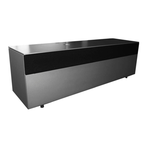
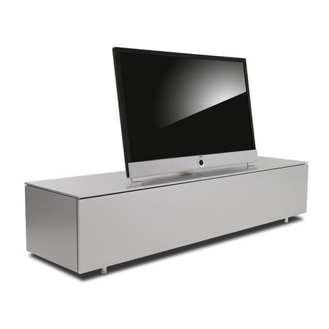
Loewe Center Speaker ID User manual

35460000
Speaker Reference ID
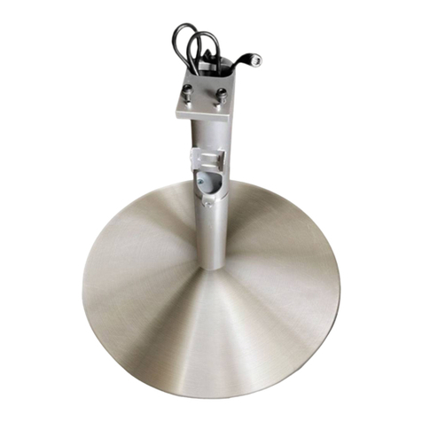
Floor Stand R ID
Floor Stand R ID Dynamic
Zubehör TV
Toebehoren TV
Accessories TV
Accessoires TV
Accessori TV
Accesorios TV
Montageanleitung, Montage-instructies, Installation instructions,
Instructions de montage, Istruzioni di montaggio, Instrucciones de montaje
Benötigtes Werkzeug d
Innensechskantschlüssel SW4
Torxschlüssel T20
(Bei Wandmontage, eine Wasserwaage)
Hinweis: Teilweise ist benötigtes Spezial-Werkzeug
im Lieferumfang beigefügt. Ggf. wird weiteres Stan-
dard-Werkzeug (nicht im Lieferumfang) benötigt.
Outils nécessaires f
Clé Allen SW4
Tournevis Torx T20
(Un niveau à bulle pour le montage sur le mur)
Remarque: dans certains cas, l'outil spécial néces-
saire est fourni dans le contenu de livraison. Au
besoin, un autre outil standard (non fourni) peut
être nécessaire.
Benodigd gereedschap l
Inbussleutel SW4
Torx-schroevendraaier T20
(Bij wandmontage, een waterpas)
Opmerking: benodigd speciaal gereedschap is ten
dele bijgeleverd. Mogelijk hebt u nog ander stan-
daardgereedschap nodig (niet bijgeleverd).
Attrezzo necessario i
Chiave a brugola SW4
Chiave Torx T20
(durante il montaggio a parete, utilizzare una livella
ad acqua)
Nota: talvolta l'attrezzo speciale necessario è com-
preso nella dotazione. Potrebbe essere necessario
un ulteriore attrezzo standard (non compreso nella
dotazione).
Required tools g
Allen key SW4
Torx screwdriver T20
(A spirit level, if the unit is being mounted onto a
wall)
Note: if a special tool is needed, this may be
included in the kit. You may require further standard
tools (these are not supplied).
Herramienta necesaria e
Llave de hexágono interior SW4
Llave Torx T20
(para el montaje en la pared un nivel de burbuja)
Nota: Se incluye en parte la herramienta especial ne-
cesaria en el volumen de suministro. Es posible que
se necesite otra herramienta especial (no incluida).
Deutschland
Loewe Opta GmbH
Customer Care Center
Industriestraße 11
D-96305 Kronach
Telefon +49 9261 99-500
Telefax +49 9261 99-515
Speaker Reference ID
Art. Nr. 52216B00
Floor Stand R ID
Art. Nr. 71726Q00
Floor Stand R ID Dynamic
Art. Nr. 71727Q00
Edition 1, 13/03 KB
Änderungen vorbehalten
Wijzigingen voorbehouden
Subject to modifications
Modifications reservée
Con riserva di modifiche
Reservado el drecho a modificaciones
Opmerking l
U hebt de mogelijkheid de kabels die uit het tv-toestel
naar buiten komen door een textielslang te leiden. Deze
textielslang behoort niet tot de levering. U kunt de
textielslang in verschillende lengten en kleuren van uw
dealer verkrijgen.
Bestelnummer textielslang: 31947 xxx
Note g
There is the option of laying the cables, which lead out
of the TV set, together in a fabric sleeve. This fabric
sleeve is not part of the scope of delivery. You can
obtain the fabric sleeve in different lengths and colours
from your specialist dealer.
Order number for fabric sleeve: 31947 xxx
Remarque f
Il est possible de mettre les câbles qui sortent du télé-
viseur dans un tuyau en tissu. Ce tuyau en tissu ne fait
pas partie du contenu de la livraison. Vous pouvez vous
procurer un tuyau en tissu de longueurs et couleurs
différentes auprès de votre revendeur.
Numéro de commande du tuyau en tissu : 31947 xxx
Nota i
Esiste la possibilità di posare i cavi che fuoriescono
dall‘apparecchio TV in un tubo flessibile in tessuto. Il
tubo flessibile in tessuto non è incluso nella dotazione.
Il tubo di tessuto può essere acquistato presso il proprio
rivenditore specializzato in lunghezze e colori diversi.
N. d’ordine tubo in tessuto: 31947 xxx
Nota: e
Los cables del aparato de televisión se pueden guiar a
través de un tubo textil. Dicho tubo no se incluye en
el volumen de suministro. Los tubos textiles se pueden
adquirir en diversos colores y tamaños en su comercio
especializado.
Número de pedido del tubo textil: 31947 xxx
Hinweis d
Es besteht die Möglichkeit die Kabel, die aus dem
TV-Gerät herausführen, in einem Gewebeschlauch
zu verlegen. Dieser Gewebeschlauch ist nicht Teil des
Lieferumfanges. Sie können den Gewebeschlauch in
unterschiedlicher Länge und Farbe von Ihrem Fach-
händler erwerben.
Bestellnummer Gewebeschlauch: 31947 xxx
Speaker Reference ID - 2 -
Montageanleitung Instructions de montage
Montage-instructies Istruzioni di montaggio
Installation instructions Instrucciones de montaje
Veiligheidsvoorschriften l
Leef de instructies in deze gebruiksaanwijzing na.
Wees voorzichtig bij de omgang met werktui-
gen. Plaats de toestelcombinatie zo, dat ze geen
gevaar vormt voor bijvoorbeeld spelende kinderen
en dat ze ook niet kan worden beschadigd.
Controleer vóór het opstellen van het toestel of
de uiteindelijke installatieplaats qua oppervlak
(drukgevoeligheid) en stabiliteit (onveranderlijk-
heid) geschikt is voor de belasting van het toestel.
Gebruik uitsluitend de door LOEWE hiervoor
aanbevolen originele onderdelen.
Verder gelden ook hier de veiligheidsinstructies
voor onze tv-toestellen.
Safety instructions g
Observe the information in the instructions. Han-
dle tools with the necessary care and attention.
Install your combination of equipment in such a
way that it presents no danger to playing children
for example and also can not be damaged.
Before positioning the set, please check that the
final location is suitable to bear the load of the
set in terms of surface (sensitivity to pressure) and
stability.
Only use the LOEWE genuine parts that are
recommended for this.
The safety instructions for our TV sets also apply
here.
Instructions de sécurité f
Veuillez observer les informations du mode d’em-
ploi. Soyez prudent lors de l’utilisation d’outils.
Positionnez votre combinaison d’appareils de telle
sorte qu’elle ne représente p. ex. aucun danger
pour des enfants en train de jouer et qu’elle ne
puisse pas être renversée.
Avant d’installer l’appareil, veuillez vérifier que
la surface (sensibilité à la pression) et la stabilité
(statique) de l’emplacement final sont adaptées à
la charge de l’appareil.
Utilisez uniquement des pièces d‘origine LOEWE
conseillées.
Par ailleurs, les instructions de sécurité relatives à
nos téléviseurs sont également valables ici.
Indicazioni di sicurezza i
Osservare le informazioni riportate nelle istruzioni.
Utilizzare gli attrezzi con la dovuta cautela.
Installare la combinazione di apparecchi in modo
tale che non possa essere danneggiata e che non
rappresenti un pericolo, ad esempio per i bambini
che giocano.
Prima di procedere con il montaggio dell’apparec-
chio, verificare se la superficie della sede definitiva
è adatta in termini di sensibilità alla pressione
e stabilità (statica) in considerazione del peso
dell’apparecchio.
Utilizzare esclusivamente i componenti originali
consigliati a questo scopo da LOEWE.
Anche in questo caso valgono le norme di sicu-
rezza relative ai nostri apparecchi TV.
Advertencias de seguridad e
Respete las instrucciones del manual. Manipule
las herramientas con las precauciones necesarias.
Instale la combinación de aparatos de manera
que no presente riesgo de lesiones, p. ej., para
niños que estén jugando cerca, y de manera que
no pueda sufrir daños.
Compruebe antes de colocar el equipo, si la posi-
ción final cuenta con la superficie (sensibilidad a
presión) y la estabilidad (estática) adecuadas para
cargar el equipo.
Emplee solo las piezas originales recomendadas
por LOEWE.
Por lo demás, las advertencias de seguridad de
nuestros televisores también tienen validez en
este caso.
Sicherheitshinweise d
Befolgen Sie die Anweisungen dieser Anleitung.
Lassen Sie im Umgang mit Werkzeug die nötige
Vorsicht walten. Stellen Sie Ihre Gerätekombinati-
on so auf, dass sie, z.B. für spielende Kinder keine
Gefährdung darstellt und auch nicht beschädigt
werden kann.
Bitte prüfen Sie vor dem Aufstellen des Gerätes,
ob der finale Standort hinsichtlich Oberfläche
(Druckempfindlichkeit) und Stabilität (Statik) für
die Belastung durch das Gerät ausgelegt ist.
Verwenden Sie nur die von LOEWE hierzu emp-
fohlenen Orginalteile.
Des weiteren haben die Sicherheitshinweise für
unsere TV-Geräte auch hier Gültigkeit.
Speaker Reference ID - 3 -
Montageanleitung Instructions de montage
Montage-instructies Istruzioni di montaggio
Installation instructions Instrucciones de montaje
Speaker Reference ID
Lieferumfang d
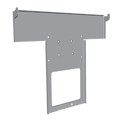
A Halteträger 2 Stück
B Abstandshalter 4 Stück
S Schrauben M5 x 10 4 Stück
T Schraubenschlüssel Torx T 20 1 Stück
SP Speaker 2 Stück
Contenu de la livraison du Speaker
Reference ID f
A Support de fixation 2 unités
B Ecarteur 4 unités
S Vis M5 x 10 4 unités
T Tournevis Torx T 20 1 unité
SP Speaker 2 unités
Speaker Reference ID
Leveringsinhoud l
A Houder 2 stuks
B Afstandshouder 4 stuks
S Schroeven M5 x 10 4 stuks
T Torx-schroevendraaier T 20 1 stuk
SP Speaker 2 stuks
Dotazione Speaker Reference ID i
A Supporto di fissaggio 2 pezzi
B Distanziale 4 pezzi
S Viti M5 x 10 4 pezzi
T Chiave Torx T 20 1 pezzo
SP Altoparlante 2 pezzi
Speaker Reference ID Delivery
specification g
A Support bracket 2 items
B Spacers 4 items
S M5 x 10 screws 4 items
T Torx screwdriver T20 1 unit
SP Speaker 2 units
Volumen de suministro de Speaker
Reference ID e
A Soporte 2 unidades
B Espaciador 4 unidades
S Tornillos M5 x 10 4 piezas
T Llave de ajuste Torx T 20 1 unidad
SP Altavoz 2 unidades
A
T
S
SP
B
Speaker Reference ID - 4 -
Montageanleitung Instructions de montage
Montage-instructies Istruzioni di montaggio
Installation instructions Instrucciones de montaje
Halteträger am Speaker montieren d
Montage du support de fixation sur
le Speaker f
Houder op de speaker monteren l
Montaggio del supporto di fissaggio
sull‘altoparlante i
Installing the support bracket to the
speaker g
Montaje del soporte en el altavoz e
l
Bescherm de gevoelige oppervlakken tegen krassen.
1
Let op de juiste oriëntering van de houder Aen
plaats de houder A op de speaker, zoals getoond.
2
Bevestig de houder Amet de schroeven S en de
torx-schroevendraaier T20 op de speaker (aanhaal-
moment ca. 1,5 Nm).
Een licht knarsgeluid bij het indraaien van de
schroeven is normaal.
g
Protect the sensitive surfaces against scratches.
1
Note the position of the support bracket Aand
place it on the speaker as shown.
2
Secure the support bracket Ato the speaker using
the screws Sand the Torx T20 screwdriver (torque
approx. 1.5 Nm).
It is normal for the screws to make a slight squea-
king noise when they are being screwed in.
f
Protégez les surfaces sensibles contre les rayures.
1
Prenez en compte le sens de montage du support
de fixation Aet positionnez le support de fixation A
sur le Speaker tel que représenté.
2
Fixez le suport de fixation A avec les vis Ssur le
Speaker au moyen du tournevis Torx T20 (couple de
serrage d'env. 1,5 Nm).
Un léger bruit de grincement lors du serrage des vis
est normal.
i
Proteggere le superfici sensibili da possibili graffi-
ature.
1
Tenere conto della direzione di applicazione del
supporto di fissaggio Ae posizionare il supporto di
fissaggio Asull'altoparlante come illustrato.
2
Fissare il supporto di fissaggio Asull'altoparlante
con le viti Saiutandosi con una chiave Torx T20 (la
coppia deve essere di ca. 1,5 Nm).
Un leggero cigolio durante il serraggio delle viti è
normale.
e
Proteja las superficies delicadas frente a posibles
arañazos.
1
Tenga en cuenta la orientación del soporte Ay
coloque el soporte A en el altavoz de la forma
mostrada.
2
Atornille al altavoz el soporte Acon los tornillos
S con ayuda de la llave de ajuste Torx T20 (par de
aprox. 1,5 Nm).
Es normal escuchar un ligero chasquido al girar los
tornillos.
1,5 Nm
Torx T20
1
2
d
Die empfindlichen Oberflächen vor Verkratzen
schützen.
1
Lagerichtung des Halteträgers Abeachten und
Halteträger A auf dem Speaker, wie dargestellt
positionieren.
2
Halteträger Amit Schrauben S, unter zuhilfenahme
des Schraubenschlüssels Torx T20, auf dem Speaker
befestigen (Drehmoment ca. 1,5 Nm).
Ein leichtes Quietschgeräusch beim Eindrehen der
Schrauben ist normal.
A
S S
S S
A
Speaker Reference ID - 5 -
Montageanleitung Instructions de montage
Montage-instructies Istruzioni di montaggio
Installation instructions Instrucciones de montaje
Abstandshalter am Speaker d
Ecarteur sur le Speaker f
Afstandhouder op de speaker l
Distanzale sull‘altoparlante i
Spacers on the speaker g
Espaciador en el altavoz e
l
Bescherm de gevoelige oppervlakken tegen krassen.
1
Maak de kleefvlakken van de afstandhouders vrij
(beschermfolie verwijderen)
2
Kleef de afstandhouder Bvast op de achterkant van
de speakers, zoals getoond in de tekening
3
De afstandhouders verhinderen dat de speaker kan
verschuiven op de wand
g
Protect the sensitive surfaces against scratches.
1
Pull off the protective films from the spacers to
expose their adhesive surfaces.
2
Affix spacer Bonto the back of the speaker as
shown in the diagram
3
When the spacers have been installed, they prevent
the speaker from slipping on the wall when it is in
operation.
f
Protégez les surfaces sensibles contre les rayures.
1
Libérez la surface adhésive (retirez le film de protec-
tion) de l’écarteur.
2
Collez l'écarteur Bsur la paroi arrière du Speaker
comme représenté sur la figure.
3
Une fois l'écarteur monté, il permet d'éviter que le
Speaker glisse sur le mur lors de son utilisation.
i
Proteggere le superfici sensibili da possibili graffi-
ature.
1
Liberare le superfici d'incollaggio dei distanziali
(rimuovere la pellicola protettiva).
2
Incollare i distanziali Bsul retro dell'altoparlante,
come illustrato nello schema.
3
I distanziali evitano che l'altoparlante possa scivola-
re sulla parete durante il suo funzionamento
e
Proteja las superficies delicadas frente a posibles
arañazos.
1
Deje al descubierto las superficies adhesivas del
espaciador (retire la lámina protectora)
2
Peque el espaciador Ben la parte trasera del altavoz
como se muestra en el esquema
3
Si monta los espaciadores evitará que el altavoz se
desplace en la pared durante el funcionamiento
1
2
3
d
Die empfindlichen Oberflächen vor Verkratzen
schützen.
1
Klebeflächen der Abstandshalter frei legen (Schutz-
folie abziehen)
2
Abstandshalter Bauf der Rückseite des Speakers,
wie auf der Skizze dargestellt ankleben
3
Wurden die Abstandshalter montert, verhindern
sie bei Betrieb des Speakers ein Verrutschen an der
Wand
B
Speaker Reference ID - 6 -
Montageanleitung Instructions de montage
Montage-instructies Istruzioni di montaggio
Installation instructions Instrucciones de montaje
Speaker an der Wand montieren d
Montage du Speaker sur le mur f
Speaker tegen de wand monteren l
Montaggio dell‘altoparlante alla
parete i
Installing the speakers to the walls g
Montaje del altavoz en la pared e
g
You are responsible for the wall's load bearing capaci-
ty and the fastening.
Because of the different wall materials and different
types of fastenings we have not included any faste-
ning material. Please buy suitable fastening parts for
your wall from a dealer.
Seek the advice of a building expert if necessary.
1
See the adjacent diagram for the dimensions of the
fastening for a brick wall.
f
Vous êtes responsable de la force portante du mur et
de la fixation.
Nous n’avons joint aucun matériel de fixation en
raison de la multitude de matériaux de construction
utilisés pour les murs et, par conséquent, des diffé-
rents types de fixation correspondants. Veuillez vous
procurer le matériel de fixation approprié à votre mur
dans un magasin spécialisé.
Demandez éventuellement conseil à un expert en
construction.
1
Vous pouvez voir sur la figure ci-contre un exemple de
dimension pour la fixation sur un mur de maçonnerie.
i
La portata della parete ed il fissaggio rientrano sotto la
responsabilità del cliente.
Il materiale delle pareti e di conseguenza i tipi di fis-
saggio possono variare notevolmente, nella fornitura
non è stato pertanto incluso alcun tipo di materiale di
fissaggio. Procurarsi il materiale di fissaggio adatto alla
propria parete presso un rivenditore specializzato.
Eventualmente richiedere la consulenza di un esperto
in materia.
1
Lo schema a lato si riferisce ad un esempio di dimensi-
oni richieste per il fissaggio ad una parete in muratura.
e
Usted será el responsable de la capacidad de carga de
la pared, así como de la fijación del dispositivo.
A causa de la elevada diversidad de los materiales de
las paredes y de los tipos de fijación, no adjuntamos el
material del fijación. Deberá adquirir el material adecu-
ado para su pared en un comercio especializado.
En caso necesario, asesórese con un especialista de la
construcción.
1
En el esquema contiguo podrá ver un ejemplo de la
dimensión de la fijación en una pared de mampostería.
.
d
Die Tragfähigkeit der Wand und die Befestigung
liegen in Ihrer Verantwortung.
Auf Grund der vielfältigen Wandbaustoffe und der
damit unterschiedlichen Befestigungsarten haben wir
kein Befestigungsmaterial beigelegt. Besorgen Sie das
für Ihre Wand geeignete im Fachhandel.
Ziehen Sie gegebenenfalls einen Bausachkundigen
zu Rate.
1
In nebenstehender Skizze sehen Sie als Beispiel die Di-
mensjon der Befestigung für einer gemauerten Wand.
Oberkante Gerät Bovenkant van
het toestel
Top edge set
Prolongación línea borde
superior del televisor
8 mm x 40 mm
5
5 mm x 40 mm
5
150,00 mm
144,75 mm
850 mm
l
U draagt zelf de volledige verantwoordelijkheid voor
het draagvermogen van de wand en de bevestiging.
Wegens de vele verschillende bouwmaterialen die al-
lemaal hun specifieke bevestigingsmiddelen vereisen,
hebben wij geen bevestigingsmateriaal bijgeleverd.
Koop het passende bevestigingsmateriaal voor uw
wand in een gespecialiseerde winkel.
Doe eventueel een beroep op een bouwexpert.
1
In de tekening hiernaast ziet als voorbeeld de afmetin-
gen voor bevestiging tegen een gemetselde muur.
Speaker Reference ID - 7 -
Montageanleitung Instructions de montage
Montage-instructies Istruzioni di montaggio
Installation instructions Instrucciones de montaje
Wandbefestigung vorbereiten d
Préparation du montage sur le mur f
Wandbevestiging voorbereiden l
Predisposizione del fissaggio alla
parete i
Preparing the wall fastening g
Preparación de la fijación de pared e
l
1
Draai de schroef zo ver in tot de ruimte tussen de
schroefkop en de wand ca. 2 mm bedraagt.
Hang de speaker om te proberen op aan de
schroeven aan de wand, en corrigeer de tussenru-
imte indien nodig.
Neem de speaker weer van de wand af om de
speakerkabels aan te sluiten.
Sluit de speakerkabel aan zoals beschreven op de
volgende pagina
g
1
Screw the screw in until there is approx. 2 mm of
space between the screw head and the wall.
Test the space by hanging the speaker onto the
screws in the wall; adjust the clearance if necessary.
Then remove the speaker from the wall and con-
nect the speaker cable to it.
Do this by following the instructions on the next
page
f
1
Serrez la vis jusqu'à ce que l'écart entre la tête de
vis et le mur soit d'env. 2 mm.
Accrochez le Speaker aux vis fixées sur le mur, et
corrigez l'écart si nécessaire.
Décrochez le Speaker du mur pour raccorder le
câble du Speaker.
Connectez le câble du Speaker comme décrit à la
page suivante.
i
1
Avvitare la vite fino ad ottenere le dimensioni della
fessura tra la testa della vite e la parete di circa 2
mm
Provare ad agganciare l'altoparlante nelle viti
applicate nella parete e correggere se necessario le
dimensioni della fessura
Togliere nuovamente l'altoparlante dalla parete per
poter collegare il cavo dell'altoparlante.
Collegare il cavo dell'altoparlante come descritto
nella pagina successiva
e
1
Gire el tornillo hasta que la ranura entre la cabeza
del tornillo y la pared sea de aprox. 2 mm
Haga una prueba de fijación del altavoz en los
tornillos de la pared y realice las correcciones
necesarias
Descuelgue de nuevo el altavoz para conectar el
cable.
Conecte el cable del altavoz como se describe en la
siguiente página
d
1
Drehen Sie die Schraube so weit ein, daß das
Spaltmaß zwischen Schraubenkopf und Wand ca.
2 mm beträgt
Hängen Sie den Speaker versuchsweise in die
Schrauben an der Wand ein, Spaltmaß wenn erfor-
derlich korrigieren
Hängen Sie den Speaker zum Anschließen des
Speakerkabels wieder von der Wand ab.
Das Speakerkabel anschließen, wie auf der nächs-
ten Seite beschrieben
2 mm
2 mm
2 mm
1
Speaker Reference ID - 8 -
Montageanleitung Instructions de montage
Montage-instructies Istruzioni di montaggio
Installation instructions Instrucciones de montaje
Speaker Reference ID anschließen d
Raccord du Speaker Reference ID f
Speaker Reference ID aansluiten l
Collegamento Speaker Reference ID i
Connecting the Speaker Reference ID g
Conexión del speaker Reference ID e
l
1
Draai de beide schroefklemmen K linksom tot de
openingen van de klemmen zichtbaar zijn.
Verbind deze zwart gemerkte draad van de speaker-
kabel Lmet de zwarte schroefklem.
De andere draad verbindt u met de rode schroef-
klem
Draai de schroefklem rechtsom om de luidspreker-
kabel vast te zetten.
g
1
Turn the two screw terminals Kanticlockwise until
the terminal openings are visible.
Connect the wires of the speaker cable L (marked
black) using the black terminal screw.
Connect the other wire to the red screw terminal.
Turn the screw terminals clockwise to fasten the
speaker cable.
f
1
Vissez les deux bornes à vis Kdans le sens contraire
des aiguilles d'une montre jusqu'à ce que les orifi-
ces des bornes soient visibles.
Reliez le brin marqué en noir du câble du Speaker L
avec la borne à vis noire.
Reliez l'autre brin avec la borne à vis rouge.
Pour fixer le câble du haut-parleur, tournez les bor-
nes à vis dans le sens des aiguilles d'une montre.
.
i
1
Far girare i due morsetti a vite Kin senso antiorario,
fino a quando non saranno visibili le aperture dei
morsetti.
Collegare il filo nero del cavo dell'altoparlante Lcon
il morsetto a vite nero.
Collegare l'altro filo con il morsetto a vite rosso
Per fissare i cavi dell'altoparlante, avvitare i morsetti
a vite in senso orario
e
1
Gire ambos bornes roscados Ken sentido contrario
a las agujas del reloj hasta que se vean los orificios
de los bornes.
Conecte el hilo negro del cable del altavoz L en el
borne roscado negro.
Conecte el otro hilo en el borne roscado rojo
Para fijar el cable del altavoz, gire los bornes rosca-
dos en el sentido de las agujas del reloj
1
d
1
Drehen Sie die beiden Schraubklemmen Kentgegen
dem Uhrzeigersinn bis die Öffnungen der Klemmen
sichtbar sind.
Die schwarz markierte Ader des Speakerkabels L
verbinden Sie mit der schwarzen Schraubklemme.
Die andere Ader verbinden Sie mit der roten
Schraubklemme
Zur Fixierung der Lautsprecherkabel drehen Sie die
Schraubklemmen im Uhrzeigersinn zu
L
K
+
-
Speaker Reference ID - 9 -
Montageanleitung Instructions de montage
Montage-instructies Istruzioni di montaggio
Installation instructions Instrucciones de montaje
Wandbefestigung d
Montage sur le mur f
Wandbevestiging l
Fissaggio alla parete i
Wall fastening g
Fijación de pared e
l
Controleer de afstand/uitsprong van de schroefkop
tot de wand. De ruimte (ca. 2 mm) tussen de schro-
efkop en de wand is noodzakelijk om de speaker in
te hangen.
1
Hang de speaker op aan de schroeven aan de wand
Wanneer er bovenaan te veel afstand is tussen de
speaker en de wand, neemt u de speaker er weer
af en draait u de schroeven een beetje verder in.
Vervolgens hangt u de speaker weer op.
g
Check the distance/projection of the screw head
from/to the wall. Approx. 2 mm of clearance is
needed between the screw head and the wall to
allow space for the speaker to be installed.
1
Hang the speaker onto the screws in the wall
If there is too much space between the top part of
the speaker and the wall, remove the speaker and
screw the screws in a little more. Then hang the
speaker back onto the screws.
f
Vérifiez l'écart/ la partie superflue de la tête de vis
par rapport au mur. Une cote d’écartement (env.
2 mm) entre la tête de vis et le mur est nécessaire
pour monter le Speaker.
1
Accrochez le Speaker aux vis fixées sur le mur.
Si le Speaker est trop éloigné du mur, décrochez-
le et vissez la vis un peu plus profondément. Puis
raccrochez le Speaker.
i
Verificare la distanza / sporgenza della testa
della vite rispetto alla parete. La dimensione della
fessura (di circa 2 mm) tra la testa della vite e la
parete è necessaria per consentire di agganciare
l'altoparlante.
1
Agganciare l'altoparlante nelle viti applicate nella
parete
e
Compruebe la distancia/saliente de la cabeza del
tornillo en la pared. Se necesita una ranura (aprox.
2 mm) entre la cabeza del tornillo y la pared para
fijar el altavoz.
1
Cuelgue el altavoz en los tornillos de la pared
Si la distancia del altavoz a la pared en la parte
superior es excesiva, retire el altavoz y apriete
ligeramente el tornillo. A continuación, vuelva a
colgar el altavoz.
d
Prüfen Sie den Abstand/ Überstand des Schrauben-
kopfes zur Wand . Spaltmaß (ca. 2 mm) zwischen
Schraubenkopf und Wand ist zum Einhängen des
Speakers notwendig.
1
Hängen Sie den Speaker in die Schrauben an der
Wand ein
Sollte der Speaker oben zur Wand zu viel Abstand
haben, nemen Sie den Speaker ab und drehen die
Schrauben noch etwas ein. Anschließend hängen
Sie den Speaker wieder ein.
1
Speaker Reference ID - 10 -
Montageanleitung Instructions de montage
Montage-instructies Istruzioni di montaggio
Installation instructions Instrucciones de montaje
Floor Stand Reference ID
Lieferumfang d
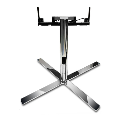
A Standrohr 2 Stück
B Fuß, Teil 1 2 Stück
C Fuß, Teil 2.. 2 Stück
D Schrauben M5 x 50 6 Stück
E Lautsprecher Anschlußabdeckung 2 Stück
F Klettbandstreifen 4 Stück
G Standpuffer 8 Stück
S Schraube (Standrohrbefestigung) M5 x 16 2 Stück
T Sechskantschlüssel SW 4 1 Stück
Floor Stand Reference ID
Contenu de la livraison f
A Tube support 2 unités
B Pied, partie 1 2 unités
C Pied, partie 2.. 2 unités
D Vis M5 x 50 6 unités
ECouvercle de raccordement de haut-parleurs
2 unités
F Bandes Velcro 4 unités
G Patins de sol 8 unités
S Vis (fixation du tube support) M5 x 16 2 unités
T Clé Allen SW 4 1 unité
Floor Stand Reference ID
Leveringsinhoud l
A Buis 2 stuks
B Voet, element 1 2 stuks
C Voet, element 2.. 2 stuks
D Schroeven M5 x 50 6 stuks
E Luidspreker aansluitafdekking 2 stuks
F Velcrostrips 4 stuks
G Voetkussentjes 8 stuks
S Schroeven (buisbevestiging) M5 x 16 2 stuks
T Inbussleutel SW 4 1 stuk
Floor Stand Reference ID
Dotazione i
A Tubo di supporto 2 pezzi
B Piede, parte 1 2 pezzi
C Piede, parte 2 2 pezzi
D Viti M5 x 50 6 pezzi
E Copertura di collegamento altoparlanti 2 pezzi
F Strisce di velcro 4 pezzi
G Cuscinetto di appoggio 8 pezzi
SVite (di fissaggio del tubo a colonna) M5 x 16
2 pezzi
T Chiave a brugola SW 4 1 pezzo
Floor Stand Reference ID
Delivery specification g
A Stand tube 2 items
B Stand, part 1 2 items
C Stand, part 2.. 2 items
D M5 x 50 screws 6 items
E Speaker connector cover 2 items
F Velcro strips 4 items
G Feet 8 items
S Screw (stand tube fastening) M5 x 16 2 items
T Allen key SW4 1 item
Floor Stand Reference ID
Volumen de suministro e
A Tubo de apoyo 2 unidades
B Pie, pieza 1 2 unidades
C Pie, pieza 2.. 2 unidades
D Tornillos M5 x 50 6 unidades
E Cubierta de conexión del altavoz 2 unidades
F Cintas de velcro 4 unidades
G Almohadilla de soporte 8 unidades
STornillo (fijación de tubo de apoyo) M5 x 16
2 unidades
T Llave hexagonal SW 4 1 unidad
A B C D
E
F G
S
T
Floor Stand R ID - 11 -
Montageanleitung Instructions de montage
Montage-instructies Istruzioni di montaggio
Installation instructions Instrucciones de montaje
Standrohr an den Speaker montieren d
Montage du tube support sur le
Speaker f
Buis op de speaker monteren l
Montaggio del tubo a colonna
sull‘altoparlante i
Installing the stand tube onto the
speaker g
Montaje del pie de apoyo en el
altavoz e
l
Bescherm de gevoelige oppervlakken tegen krassen.
1
Schroef de buis A op de speaker.
Gebruik de schroef Sen de bijgeleverde inbussleutel
T SW 4
2
Draai de schroeven Smet geringe kracht (aanhaal-
moment ca. 2Nm) vast.
3
Gemonteerde buis
g
Protect the sensitive surfaces against scratches.
1
Screw the stand tube Aonto the speaker.
Use the screw Sand the T SW 4 allen key that is
included
2
Use a little force to tighten the screws S(approx 2
Nm torque).
3
Completely installed stand tube
f
Protégez les surfaces sensibles contre les rayures.
1
Vissez le tube support Aau Speaker.
Utilisez la vis Set la clé Allen T SW 4 contenue dans
la livraison.
2
Serrez la vis Savec peu de force (couple de serrage
env. 2 Nm).
3
Le tube support est monté.
i
Proteggere le superfici sensibili da possibili graffi-
ature.
1
Fissare il tubo a colonna Asull'altoparlante.
Utilizzare la vite Se la chiave a brugola T SW 4 in
dotazione
2
Serrare leggermente le viti S(coppia ca. 2 Nm).
3
Tubo a colonna finito
e
Proteja las superficies delicadas frente a posibles
arañazos.
1
Atornille el tubo de apoyo A en el altavoz.
Emplee el tornillo Sy la llave hexagonal T SW 4,
incluida en el volumen de suministro
2
Fije el tornillo Sligeramente (par aprox. 2Nm).
3
Tubo de apoyo montado
1
2
d
Die empfindlichen Oberflächen vor Verkratzen
schützen.
1
Schrauben Sie das Standrohr A an den Speaker.
Verwenden Sie die Schraube Sund den im Liefer-
umfang enthaltenen Sechskantschlüssel T SW 4
2
Schrauben S, mit kleiner Kraft (Drehmoment ca.
2Nm) festziehen.
3
Fertig anmontiertes Standrohr
S
3
A
A
S
A
T
SW 4
Floor Stand R ID - 12 -
Montageanleitung Instructions de montage
Montage-instructies Istruzioni di montaggio
Installation instructions Instrucciones de montaje
Standfuß montieren d
Montage du pied f
Voet monteren l
Montaggio del piede di appoggio i
Installing the floor stand g
Montaje del pie de apoyo e
l
Bescherm de gevoelige oppervlakken tegen krassen.
1
Schuif het voetelement Ben het voetelement C
zoals getoond in de inkepingen van element A
2
De elementen Ben C zet u vast met de 3 schroeven
D, zoals getoond.
Draai de schroeven met ca. 2 Nm vast
3
De in de tekening met Xgemarkeerde boring blijft
nog vrij voor de aansluitkabel.
g
Protect the sensitive surfaces against scratches.
1
Insert floor stand part Band Cinto the cross slot
of part A
2
Secure parts Band C with the 3 screws Das
shown.
Tighten the screws with approx. 2 Nm
3
The hole marked Xin the diagram remains initially
free for the connecting cable.
f
Protégez les surfaces sensibles contre les rayures.
1
Insérez la partie du pied Bet la partie du pied C
tel que représenté dans le logement croisé de la
partie A.
2
Fixez les parties Bet Cau moyen des 3 vis D, tel
que représenté.
Serrez les vis avec env. 2 Nm.
3
L'orifice indiqué par un X sur la figure reste pour
l'instant libre pour le câble de raccordement.
i
Proteggere le superfici sensibili da possibili graffi-
ature.
1
Far scorrere la parte del piede Be la parte del piede
Ccome illustrato nelle scanalature incrociate della
parte A
2
Fissare le parti Be Ccon le 3 viti Dcome illustrato.
Serrare le viti con ca. 2 Nm
3
Il foro contrassegnato con la Xnello schema rimane
disponibile per il cavo di collegamento.
e
Proteja las superficies delicadas frente a posibles
arañazos.
1
Introduzca la pieza cónica By la pieza cónica C
en las ranuras en cruz de la pieza A de la forma
mostrada
2
Fije las piezas By C con los 3 tornillos D de la
forma mostrada.
Fije los tornillos con un par de aprox. 2 Nm
3
EL orificio indicado con una Xen el esquema
quedará libre para conectar el cable.
d
Die empfindlichen Oberflächen vor Verkratzen
schützen.
1
Schieben Sie das Fußteil Bund das Fußteil C, wie
dargestellt in die Kreuznuten von Teil Aein
2
Die Teil Bund C sichern Sie mit den 3 Schrauben D,
wie dargestellt.
Die Schrauben mit ca. 2 Nm festziehen
3
Die in der Skizze mit Xbezeichnete Bohrung bleibt
zunächst für das Anschlußkabel frei.
1
2
2,0 Nm
2,0
N
m
3
X
B
A
C
D
T
SW 4
Floor Stand R ID - 13 -
Montageanleitung Instructions de montage
Montage-instructies Istruzioni di montaggio
Installation instructions Instrucciones de montaje
Standpuffer einsetzen d
Montage des patins de sol f
Voetkussentjes aanbrengen l
Inserimento del cuscinetto di ap-
poggio i
Inserting the feet g
Colocación de las almohadillas de
soporte e
l
Bescherm de gevoelige oppervlakken tegen krassen.
1
Leg de speaker met gemonteerde voet op een
zachte ondergrond om de voetkussentjes aan te
brengen
2
Verwijder de beschermfolie van de kleefvlakken van
de 4 voetkussentjes
3
Breng de voetkussentjes aan in de boringen van
voetelementen A en B, zoals getoond
g
Protect the sensitive surfaces against scratches.
1
When inserting the feet, place the speaker on a soft
underlay as shown with the floor stand installed
2
Remove the protective film from the adhesive
surface of the 4 feet
3
Place the feet into the holes of floor stand parts A
and B as shown
f
Protégez les surfaces sensibles contre les rayures.
1
Posez le Speaker avec le pied monté sur une surface
douce pour monter les patins de sol.
2
Retirez le film de protection de la surface adhésive
des 4 patins de sol.
3
Insérez les patins de sol dans les orifices des pieds A
et B tel que représenté.
i
Proteggere le superfici sensibili da possibili graffi-
ature.
1
Mettere l'altoparlante in posizione sdraiata su
una superficie morbida, con il piede di appoggio
rivolto in modo da poter applicare il cuscinetto di
appoggio
2
Rimuovere la pellicola protettiva della superficie
adesiva dei 4 cuscinetti
3
Inserire i cuscinetti di appoggio nei fori del piede A
e B come illustrato
e
Proteja las superficies delicadas frente a posibles
arañazos.
1
Coloque el altavoz con el pie montado en una su-
perficie blanda para fijar las almohadillas de soporte
2
Retire la lámina protectora de la superficie adhesiva
de las 4 almohadillas de soporte
3
Coloque las almohadillas de soporte en los orificios
de las piezas cónicas A y B de la forma indicada
d
Die empfindlichen Oberflächen vor Verkratzen
schützen.
1
Legen Sie den Speaker mit montiertem Standfuß
zum Einsetzen der Standpuffer auf eine weiche
Unterlage
2
Ziehen Sie die Schutzfolie an der Klebefläche der 4
Standpuffer ab
3
Setzen Sie die Standpuffer in die Bohrungen von
Fußteil A und B,wie dargestellt ein
Z
1
2
3
Floor Stand R ID - 14 -
Montageanleitung Instructions de montage
Montage-instructies Istruzioni di montaggio
Installation instructions Instrucciones de montaje
Kabel anschließen d
Raccordement du câble f
Kabel aansluiten l
Collegamento dei cavi i
Connecting the cables g
Conexión de cables e
l
Bescherm de gevoelige oppervlakken tegen krassen.
1
Leg de speaker met gemonteerde voet op een
zachte ondergrond om de kabel aan te sluiten zoals
getoond in de tekening
2
Schuif de luidsprekerkabel in de met pijl X
aangeduide boring, tot hij zichtbaar wordt in de
aansluitzone Z
3
Aansluitzone Zop de speaker
Een nauwkeurige beschrijving voor het aansluiten
vindt u op pagina 9
g
Protect the sensitive surfaces against scratches.
1
When connecting the cable, place the speaker
on a soft underlay as shown with the floor stand
installed
2
Insert the speaker cable into the hole marked with
the arrow X until it can be seen in the connecting
area Z
3
Connection area Zon the speaker
See page 9 for a more detailed description of how
to connect the cables
f
Protégez les surfaces sensibles contre les rayures.
1
Posez le Speaker avec le pied monté sur une surface
douce pour raccorder le câble, tel que représenté.
2
Faites glisser le câble des haut-parleurs dans l'orifice
indiqué par une flèche X jusqu'à ce qu'il soit visible
dans la zone de raccordement Z.
3
Zone de raccordement Zsur le Speaker.
Description détaillée des raccordements à la page 9.
i
Proteggere le superfici sensibili da possibili graffi-
ature.
1
Mettere l'altoparlante in posizione sdraiata su una
superficie morbida, con il piede di appoggio per il
collegamento dei cavi come illustrato
2
Far scorrere il cavo dell'altoparlante nel foro indica-
to con la freccia X, fino a rendere visibile la zona di
collegamento Z.
3
Zona di collegamento Zsull'altoparlante
Per una descrizione dettagliata in merito al collega-
mento, vedere a pagina 9
e
Proteja las superficies delicadas frente a posibles
arañazos.
1
Coloque el altavoz con el pie montado en una
superficie blanca para conectar el cable de la forma
mostrada
2
Introduzca el cable del altavoz en el orificio indica-
do con la flecha X hasta que se vea en el área de
conexión Z
3
Área de conexión Zen el altavoz
Descripción detallada de la conexión en la página 9
d
Die empfindlichen Oberflächen vor Verkratzen
schützen.
1
Legen Sie den Speaker mit montiertem Standfuß
zum Anschließen der Kabel, wie dargestellt auf eine
weiche Unterlage
2
Schieben Sie das Lautsprecherkabel in die mit Pfeil X
bezeichnete Bohrung ein, bis es im Anschlußbereich
Zzu sehen ist
3
Anschlußbereich Zam Speaker
Genaue Beschreibung zum Anschließen, auf Seite 9
Z
X
1
2
3
+
-
Floor Stand R ID - 15 -
Montageanleitung Instructions de montage
Montage-instructies Istruzioni di montaggio
Installation instructions Instrucciones de montaje
Anschlußabdeckung d
Couvercle de raccordement f
Aansluitafdekking l
Copertura dei collegamenti i
Connector cover g
Cubierta de conexión e
l
Bescherm de gevoelige oppervlakken tegen krassen.
1
Vervolgens neemt u de beide velcrostrips F en de
luidsprekeraansluitafdekking Eter hand
2
Kleef de beide velcrostrips Fzoals getoond in de
aansluitzone van de speaker
3
Deze zone sluit u vervolgens af met de luidsprekera-
ansluitafdekking E
g
Protect the sensitive surfaces against scratches.
1
Next, pick up both the Velcro strips F and the
speaker connector cover E
2
Attach the two Velcro strips Fto the connecting
area of the speaker as shown in the diagram
3
Cover this area with the speaker connector cover E
f
Protégez les surfaces sensibles contre les rayures.
1
Prenez ensuite les deux bandes Velcro Fet le cou-
vercle de raccordement des haut-parleurs E.
2
Collez les deux bandes Velcro Fcomme représenté
sur la zone de raccordement du Speaker.
3
Puis refermez cette zone avec le couvercle de
raccordement des haut-parleurs E.
i
Proteggere le superfici sensibili da possibili graffi-
ature.
1
Prendere le due strisce di velcro F e la copertura
degli altoparlanti Ea portata di mano
2
Incollare le due strisce di velcro Fcome illustrato
nella zona di collegamento degli altoparlanti
3
Questa zona viene chiusa con la copertura dei
collegamenti degli altoparlanti E
e
Proteja las superficies delicadas frente a posibles
arañazos.
1
A continuación, coja las dos cintas de velcro F y la
cubierta del altavoz E
2
Pegue las dos cintas de velcro Fde la forma mostra-
da en el área de conexión del altavoz
3
Esta área se cierra con la cubierta de conexión del
altavoz E
d
Die empfindlichen Oberflächen vor Verkratzen
schützen.
1
Als nächstes nehmen Sie die beiden Klettstreifen F
und die Lautsprechanschlußabdeckung Ezur Hand
2
Kleben Sie die beiden Klettbandstreifen F, wie dar-
gestellt im Anschlußbereich des Speakers ein
3
Diesen Bereich verschließen Sie mit der Lautspre-
cheranschlußabdeckung E
1
2
3
E
F
F
F
E
Floor Stand R ID - 16 -
Montageanleitung Instructions de montage
Montage-instructies Istruzioni di montaggio
Installation instructions Instrucciones de montaje
Floor Stand Reference ID d
Floor Stand Reference ID f
Floor Stand Reference ID l
Floor Stand Reference ID i
Floor Stand Reference ID g
Floor Stand Reference ID e
l
Bescherm de gevoelige oppervlakken tegen krassen.
Reinigingsinstructies vindt u op pagina 26
1
Floor Stand Reference ID, achteraanzicht
2
Floor Stand Reference ID, vooraanzicht.
g
Protect the sensitive surfaces against scratches.
See page 28 for cleaning tips
1
Floor Stand Reference ID, rear view.
2
Floor Stand Reference ID, front view.
f
Protégez les surfaces sensibles contre les rayures.
Vous trouverez les consignes de nettoyage à la
page 30
1
Floor Stand Reference ID, vue arrière
2
Floor Stand Reference ID, vue avant.
3
Visser l'unité de rotation (C) sur les étais (A) et (B)
avec les 3 vis cylindriques M5x55, SW3.
i
Proteggere le superfici sensibili da possibili graffi-
ature.
Le istruzioni di pulizia sono riportate a pagina 32
1
Floor Stand Reference ID, vista posteriore
2
Floor Stand Reference ID, vista anteriore.
3
Fissare l'unità di rotazione (C) con le viti sugli
archetti (A) e (B) con 3 viti a testa cilindrica M5x55,
SW3.
e
Proteja las superficies delicadas frente a posibles
arañazos.
Encontrará las indicaciones de limpieza en la página
34
1
Floor Stand Reference ID, vista desde atrás
2
Floor Stand Reference ID, vista desde la parte
delantera
d
Die empfindlichen Oberflächen vor Verkratzen
schützen.
Reinigungshinweise finden Sie auf Seite 24
1
Floor Stand Reference ID, Ansicht von hinten
2
Floor Stand Reference ID, Ansicht von vorn.
2
1
Floor Stand R ID - 17 -
Montageanleitung Instructions de montage
Montage-instructies Istruzioni di montaggio
Installation instructions Instrucciones de montaje
Floor Stand R ID Dynamic
Lieferumfang d
A Stütze 2 Stück
B Abdeckung 2 Stück
D Bodengleiter 4 Stück
E Schrauben M5 x 14 8 Stück
Floor Stand R ID Dynamic
Contenu de la livraison f
A Support 2 unités
B Couvercle 2 unités
D Patins de sol 4 unités
E Vis M5 x 14 8 unités
Floor Stand R ID Dynamic
Leveringsinhoud l
A Steunen 2 stuks
B Afdekking 2 stuks
D Vloerglijders 4 stuks
E Schroeven M5 x 14 8 stuks
Floor Stand R ID Dynamic
Dotazione i
A Supporto 2 pezzi
B Copertura 2 pezzi
D Guida da pavimento 4 pezzi
E Viti M5 x 14 8 pezzi
Floor Stand R ID Dynamic
Delivery specification g
A Support bracket 2 items
B Cover 2 items
D Floor glider 4 items
E M5 x 14 screws 8 items
Floor Stand R ID Dynamic
Volumen de suministro e
A Soporte 2 unidades
B Cubierta 2 unidades
D Protector de suelo 4 unidades
E Tornillos M5 x 14 8 unidades
B
A
D E
Floor Stand R ID Dynamic - 18 -
Montageanleitung Instructions de montage
Montage-instructies Istruzioni di montaggio
Installation instructions Instrucciones de montaje
Bodengleiter montieren d
Montage des patins de sol Montage
des patins de sol f
Vloerglijders monteren l
Montaggio delle guide da pavimen-
to i
Installing the floor glider g
Montaje del protector de suelo e
l
Bescherm de gevoelige oppervlakken tegen krassen.
Reinig de montagevlakken / kleefvlakken voor
de vloerglijders Dop de speaker met een droge
pluisvrije doek
1
Verwijder de beschermfolie Fvan de kleefvlakken
van de vloerglijders D
2
Hang de vloerglijder in de speaker zoals getoond in
de tekening, schuif hem in de juiste positie en druk
het kleefvlak van de vloerglijder aan
g
Protect the sensitive surfaces against scratches.
Use a dry, low-linting cloth to clean the speaker,
installation surface and adhesive service for the
floor glider D
1
Remove protective film Ffrom the adhesive surface
on the floor glider D
2
Insert the floor glider into the speaker as shown,
slide it into position and then press down its
adhesive surface.
f
Protégez les surfaces sensibles contre les rayures.
Sur le Speaker, nettoyez avec un chiffon sec et sans
peluche la surface de montage / la surface adhésive
pour les patins de sol D.
1
Retirez le film de protection Fde la surface adhésive
sur les patins de sol D.
2
Montez les patins de sol sur le Speaker comme
représenté sur la figure, placez-les correctement et
appuyez sur la surface adhésive des patins de sol.
i
Proteggere le superfici sensibili da possibili graffi-
ature.
Sull'altoparlante, pulire la superficie di montaggio /
di incollaggio per le guide da pavimento Dcon un
panno umido che non crei pelucchi
1
Rimuovere la pellicola protettiva Fdalla guida da
pavimento D
2
Fissare il gommino da pavimento come illustrato
nello schema, farlo scorrere in posizione e premere
la superficie di incollaggio la guida da pavimento.
e
Proteja las superficies delicadas frente a posibles
arañazos.
En el altavoz, limpie la superficie de montaje/super-
ficie adhesiva del protector de suelo Dcon un paño
seco y sin pelusa
1
Retire la lámina protectora Fde la superficie adhesi-
va del protector de suelo D
2
Enganche el protector de suelo en el altavoz,
colóquelo en su posición y presione la superficie
adhesiva del protector de suelo
d
Die empfindlichen Oberflächen vor Verkratzen
schützen.
Am Speaker, Montagefläche / Klebefläche für die
Bodengleiter Dmit einem trockenen fusselarmen
Tuch reinigen
1
Schutzfolie Fder Klebefläche am Bodengleiter D
abziehen
2
Bodengleiter wie in Skizze dargestellt am Speaker
einhängen, an Position schieben und Klebefläche
des Bodengleiters andrücken
2
1
F
D
Floor Stand R ID Dynamic - 19 -
Montageanleitung Instructions de montage
Montage-instructies Istruzioni di montaggio
Installation instructions Instrucciones de montaje
Stütze montieren d
Montage du support f
Steun monteren l
Montaggio del supporto i
Installing the support bracket g
Montaje del soporte e
l
Bescherm de gevoelige oppervlakken tegen krassen.
1
Bevestig de steun Amet de 4 schroeven E zoals
getoond aan de speaker
2
Draai de 4 schroeven E in met behulp van een torx-
schroevendraaier T 20 (bijgeleverd bij de Speaker
Reference). Aanhaalmoment ca. 1,5 Nm
g
Protect the sensitive surfaces against scratches.
1
Secure support bracket Ato the speaker using the
4 screws E, as shown in the diagram
2
Screw the 4 screws Ein using a Torx T 20 screwdri-
ver (included with the Speaker Reference). Torque
approx. 1.5 Nm
f
Protégez les surfaces sensibles contre les rayures.
1
Fixez le support Aavec les 4 vis Eau Speaker, tel
que représenté sur la figure.
2
Vissez les 4 vis Eà l'aide du tournevis Torx T 20
(contenu dans la livraison du Speaker Reference).
Couple de serrage env. 1,5 Nm
i
Proteggere le superfici sensibili da possibili graffi-
ature.
1
Fissare il supporto Acon le 4 viti Esull'altoparlante
come illustrato.
2
Serrare le 4 viti E con l'ausilio dell'apposita chiave
Torx T 20 (in dotazione con l'altoparlante Refe-
rence). Coppia di circa 1,5 Nm
e
Proteja las superficies delicadas frente a posibles
arañazos.
1
Fije el soporte Acon los 4 tornillos E al altavoz de
la forma mostrada
2
Atornille los 4 tornillos Econ ayuda de la llave de
ajuste Torx T 20 (incluida en el volumen de suminis-
tro de Speaker Reference). Par de aprox. 1,5 Nm
d
Die empfindlichen Oberflächen vor Verkratzen
schützen.
1
Stütze Amit den 4 Schrauben E, wie dargestellt am
Speaker befestigen
2
Die 4 Schrauben E mit Hilfe des Schraubenschlüs-
sels Torx T 20 (im Liefereumfang Speaker Reference
enthalten) einschrauben. Drehmoment ca. 1,5 Nm
1
1,5 Nm
Torx T20
2
A
E
E
E
E E
Floor Stand R ID Dynamic - 20 -
Montageanleitung Instructions de montage
Montage-instructies Istruzioni di montaggio
Installation instructions Instrucciones de montaje

Other manuals for Center Speaker ID

1

This manual suits for next models

5

Other Loewe TV Accessories manuals
Loewe FLOOR STAND 5 MU User manual

Loewe

Loewe FLOOR STAND 5 MU User manual

Loewe Dolby Digital Decoder system User manual

Loewe

Loewe Dolby Digital Decoder system User manual

Loewe Digital Recorder + User manual

Loewe

Loewe Digital Recorder + User manual

Loewe FSM 7 User manual

Loewe

Loewe FSM 7 User manual

Loewe Table Stand I 40 Sound User manual

Loewe

Loewe Table Stand I 40 Sound User manual

Loewe VESA Art 42/47 User manual

Loewe

Loewe VESA Art 42/47 User manual

Loewe SL3 series User manual

Loewe

Loewe SL3 series User manual

Loewe 32-40 User manual

Loewe

Loewe 32-40 User manual

Loewe Rack 165.30 User manual

Loewe

Loewe Rack 165.30 User manual

Loewe Network Mediaplayer Accessories TV User manual

Loewe

Loewe Network Mediaplayer Accessories TV User manual

Loewe VESA Size Adapte Instruction Manual

Loewe

Loewe VESA Size Adapte Instruction Manual

Loewe TS 7.55 User manual

Loewe

Loewe TS 7.55 User manual

Loewe Connect 40-55 User manual

Loewe

Loewe Connect 40-55 User manual

Loewe 2 T-CI User manual

Loewe

Loewe 2 T-CI User manual

Loewe Floor Stand Connect ID 32-46 User manual

Loewe

Loewe Floor Stand Connect ID 32-46 User manual

Loewe floor stand motor s.77 User manual

Loewe

Loewe floor stand motor s.77 User manual

Loewe Equipment Board FS Trapeze User manual

Loewe

Loewe Equipment Board FS Trapeze User manual

Loewe 68482 Series User manual

Loewe

Loewe 68482 Series User manual

Loewe VESA C 32 User manual

Loewe

Loewe VESA C 32 User manual

Loewe 67202 Series User manual

Loewe

Loewe 67202 Series User manual

Loewe Individual 40 SL 220 User manual

Loewe

Loewe Individual 40 SL 220 User manual

Loewe 69476 Series User manual

Loewe

Loewe 69476 Series User manual

Loewe WM Flex 26 S User manual

Loewe

Loewe WM Flex 26 S User manual

Loewe Floor Stand I 55 SP User manual

Loewe

Loewe Floor Stand I 55 SP User manual

Popular TV Accessories manuals by other brands

LG SP520 owner's manual

LG

LG SP520 owner's manual

Philips SVC1116F/27 user manual

Philips

Philips SVC1116F/27 user manual

ActionTec MyWirelessTV MWTV200KIT quick start guide

ActionTec

ActionTec MyWirelessTV MWTV200KIT quick start guide

SunnyCam xtreme edition user guide

SunnyCam

SunnyCam xtreme edition user guide

SpinDance PlayLimit user guide

SpinDance

SpinDance PlayLimit user guide

Contemporary Research ICC2-IRC product manual

Contemporary Research

Contemporary Research ICC2-IRC product manual

Premier Mounts CTM-MS1 Brochure & specs

Premier Mounts

Premier Mounts CTM-MS1 Brochure & specs

Kenwood KSP-1000 instruction manual

Kenwood

Kenwood KSP-1000 instruction manual

Kathrein HDS 910 operating manual

Kathrein

Kathrein HDS 910 operating manual

DRAKE DIP42 datasheet

DRAKE

DRAKE DIP42 datasheet

P3 International Save A Watt P4150 operating manual

P3 International

P3 International Save A Watt P4150 operating manual

Techly ica-tr4 user manual

Techly

Techly ica-tr4 user manual

Kathrein ESD 08 Specification sheet

Kathrein

Kathrein ESD 08 Specification sheet

Philips SWV2034 Specifications

Philips

Philips SWV2034 Specifications

Philips SVC2540 Specification sheet

Philips

Philips SVC2540 Specification sheet

Sony TDGBT500A operating instructions

Sony

Sony TDGBT500A operating instructions

Terrestrial Signal Finder Terrestrial Signal Finder user manual

Terrestrial Signal Finder

Terrestrial Signal Finder Terrestrial Signal Finder user manual

Zenith ITV user guide

Zenith

Zenith ITV user guide

manuals.online logo
manuals.online logoBrands
  • About & Mission
  • Contact us
  • Privacy Policy
  • Terms and Conditions

Copyright 2025 Manuals.Online. All Rights Reserved.