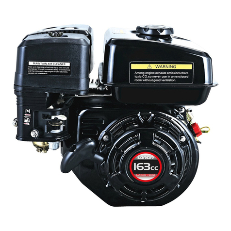
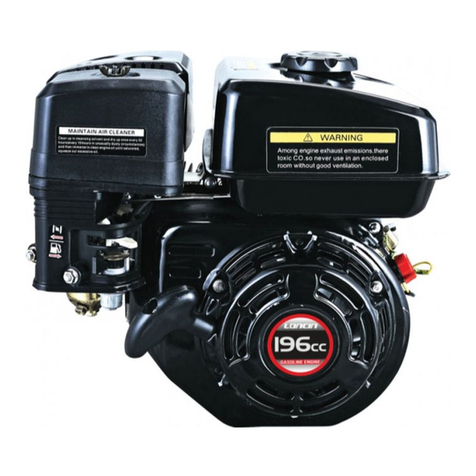
LONCIN G120F Install guide

G120F/G160F/G200FContents
- 1 -
G120F G160F G200F
Shop manual
LoncinMotorCo., LTD

G120F/G160F/G200FContents
- 2 -
Contents
PartIspecifications 3
1-1Introduction 3
1-2Productparameters 4
1-3Dimensions(boundaryandmounting dimensions) 6
1-4PTO assemblydrawing 8
1-5Wiringdiagrams 10
PartIIDescriptionofmaintenance 12
2-1Safetyprecautions 12
2-2Maintenance standards 14
2-3Torquevalues 16
2-4Troubleshooting 17
PartIIIMaintenance 22
3-1Maintenance schedule 22
3-2Engineoil 23
3-3Oil alertsysteminspection 24
3-4Aircleaner 25
3-5Muffler 26
3-6Fuel filteringsystem 27
3-7Sparkplug 28
3-8Carburetor(idlespeed) 29
3-9Valveclearance 29
3-10 Governor 30
PartIVDisassemblyandmaintenance 31
4-1Aircleanerandmuffler 31

G120F/G160F/G200FContents
- 2 -
4-2Starterandcontrolbox 33
4-3Carburetor 37
4-4Fuel tankandspeedgoverningsystem 39
4-5Flywheel, ignitioncoil, startermotorandlightingcoil 40
4-6Cylinderheadandvalves 44
4-7Crankcase body, piston, connectingrod andcrankshaft 50
4-8Governinggearandfuel level switch 58
4-9Reductionsystem 60
4-10 Battery 63

G120F/G160F/G200FPartI specifications
- 3 -
1-1 Introduction
Aircleaner—protectstheenginethrough
removing dustand otherimpurities intheair.
Sparkplug—deliversthehigh voltageofthe
ignition coil intotheengine’scombustion
chamber, and produces sparksbyelectric
dischargebetweenelectrodes, toignitethe
fuel-airmixture.
Muffler—preventstheenginenoise from
traveling, soas tolowernoise oftheexhaust
system.
Fuel cock—aswitchinthefuel linetocontrol
thefuel flowinthefuel line.
Recoil starter—serves tostarttheengine
Choke lever—closes thechoke before
engine’scoldstarting, and thecarburetorwill
deliveraveryrichmixturetolettheenginebe
easilystartable. Whentheenginehas warmed
up, thechoke levershall befullyopened.
Engineswitch—beforestarting theengine,the
switchshall beputintheONposition;ifyou
puttheswitchintheOFFposition theengine
will beshutdown
Throttlelever—serves toadjusttheengine
speed, soastoobtainthepowerand speed
you want.
Fuel tankcap—whenloosened, fuel canbe
addedintothefuel tank;whentightened, fuel
canbesealedinthefuel tank.
Fuel tank—stores thefuel and deliversfuel to
thecarburetor.
Oil drainplug—whenloosened, all engineoil
intheenginecanbedrainedoff sothatengine
oil canbechanged
1-1.Introduction 1-2. Productparameters 1-3. Dimensions(boundaryand
mounting dimensions) 1-4. PTO assemblydrawing 1-5. Wiring diagrams
Startergrip
Muffler
Sparkplug
Engineswitch
Aircleaner
Choke lever
Recoil starter
Fuel cock
Throttlelever
Oil drainplug
Fuel tank
Fuel tankcap

G120F/G160F/G200FPartI specifications
- 4 -
1-2Productparameters
Engine model G120F G160F/ G160FD G200F/ G200FD
Engine type Singlecylinder, 4-Stroke, Forced AirCooling, OHV25°
Net power(KW/3600rpm) 2.6 3.6 4.1
Net torque (N m/rpm) 7.3/2500 9.9/2500 12.4/2500
Bore×stroke(mm) 60×42 68×45 68×54
Displacement (cc) 118 163 196
Compression ratio 8.5:1 8.5:1 8.5:1
Engine oil capacity(L) 0.6 0.6 0.6
Fuelconsumption rate
(g/KW.h) ≤395
Engine oil consumption rate
(g/KW.h) ≤6.8
Idlespeed (r/min) 1400±150
Noise(≤7m) 70dBA
Startingmode Recoil Recoil /Electric
Noise(≤7m) 70dBA
Lubrication mode Splash
Coolingsystem Forced aircooling
Stoppingmode Grounding
Fuel Unleaded gasolineforvehicles
PTO shaft rotation Counterclockwise(seen fromthe end ofoutput shaft)
Ignition system T.C.I.
Ignition timing 25°BTDC (fixed)
Aircleanertype Semi-dry, oil bath, foamfilter
Carburetor Horizontalbutterflyvalve
Boundarydimension
(L.W.H) 305×341×318 312×362×335 312×362×335
Dryweight (kg) 13 15(18) 16(19)

G120F/G160F/G200FPartI specifications
- 5 -
Engine model G160F(D)-B G200F(D)-B G160F(D)-C G200F(D)-C
Engine type Singlecylinder, 4-Stroke, Forced AirCooling, OHV25°
Net power(KW/4000rpm) 3.6 4.1 3.6 4.1
Net torque (N m/rpm) 19.8/1250 24.8/1250 19.5/1250 24.8/1250
Poweroutputmode Clutch Chain
Reduction ratio 21
Bore×stroke(mm) 68×45 68×54 68×45 68×54
Displacement (cc) 163 196 163 196
Compression ratio 8.5:1 8.5:1 8.5:1 8.5:1
Engine oil capacity(L) 0.6 0.6 0.6 0.6
Fuelconsumption rate
(g/KW.h) ≤395 ≤395 ≤395 ≤395
Engine oil consumption rate
(g/KW.h) ≤6.8
Idlespeed (r/min) 1400±150
Noise(≤7m) 70dBA
Startingmode Recoil /Electric
Lubrication mode Forced splash
Coolingsystem Forced aircooling
Stoppingmode Grounding
Fuel Unleaded gasolineforvehicles
PTO shaft rotation Counterclockwise(seen fromthe end ofoutput shaft)
Ignition system T.C.I.
Ignition timing 25°BTDC (fixed) 25°BTDC (fixed)
Aircleaner Paperand foamfilters
Carburetor Horizontalbutterflyvalve
Boundarydimension
(L.W.H) 391×362×335 391×376×335 342×362×335 342×376×335
Dryweight(kg)19(22)20(23)15.5(18.5)16.5(19.5)

G120F/G160F/G200FPartI specifications
- 6 -
1-3Dimensions(boundaryandmountingdimensions)
G120F

G120F/G160F/G200FPartI specifications
- 7 -
G160F/G200F

G120F/G160F/G200FPartI specifications
- 8 -
1-4PTOassemblydrawing
G120F/G160F/G200F
ATypeCType
RTypeDType
Tocrankcase
c
over
mount
surface
Tocrankcase
c
over
mount
surface
Tocrankcase
c
over
mount
surface
Tocrankcase
c
over
mount
surface

G120F/G160F/G200FPartI specifications
- 9 -
ETypeSType
UTypeA22 Type
Tocrankcase
c
over
mount
surface
Tocrankcase
c
over
mount
surface
Tocrankcase
c
over
mount
surface
Tocrankcase
c
over
mount
surface

G120F/G160F/G200FPartI specifications
- 10 -
1-5 Wiringdiagrams
Wirecolorsand codes Combinationswitch
BI Black Br Brown
Y Yellow R Red
W White G Green
IG E BAT ST
OFF ○○
ON
START
○○
1. Withoil alertandelectricstarter
Controlbox
Rectifier
Ignitor
Chargingcoil
Sparkplug
Oil levelswitch
Oil alert unit
Circuit
breaker
Engine switch
Startermotor
Battery
Startersolenoid
Fuse
W
Bl/W
Bl
Bl/R
Bl
Y
W
W
W
Br
W
W

G120F/G160F/G200FPartI specifications
- 11 -
2. Withoilalertandwithoutelectricstarter
Ignitor
Sparkplug
Oil alert unit
Oil levelswitch
Engineswitch

G120F/G160F/G200FPartII Description ofmaintenance
- 12 -
2-1Safetyprecautions
1.Parts,oil and grease mustbegenuine
LONCINproductsorproducts
designatedbyLoncin
2.Worktobedonewithspecialtoolsmust
bedonewithsuchtools.
3.Gaskets,washers,O-ringsand oil seals
mustbereplacedafterdisassembly.
4.Whenscrewingbolts,nutsorscrews,
beginwiththelarger-diameterinnerone,
and tighteninacrisscrosspatterntothe
specifiedtorquediagonally.
5.Cleanpartsincleaning solventupon
disassembly.Lubricateanysliding
surfaces beforereassembly.
6.Afterreassembly,check allpartsfor
properinstallation and operation.
7.Don’tmaintainunless theengineis
stoppedand has cooled,otherwise,bun
canhappeninthehotstateofengine.
8.Ifyou wanttoperformatestrun ofthe
engineintheworkarea after
maintenance,take caretoensure
adequateventilation inthearea,and
neversmoke orfirenearfuel, grease or
otherflammablematerials.
2-1.Safetyprecautions 2-2. Maintenance standards 2-3. Torquevalues
2-4. Troubleshooting

G120F/G160F/G200FPartII Description ofmaintenance
- 13 -
9.Self-tappingbolts(capableoftapping
whilebeingscrewedin)areusedfor
someportionsoftheengine;take care
nottodamagetheirthreads.Ifthreadof
anyofthemisdamaged, replaceitwitha
standardboltforthesamehole.
10.Jointseamsofthefueltankarejoined
withadhesive,ifyou uselocalwelding,
thehottemperaturemay causeadhesive
tofall off.Ifitisnecessarytouse
welding,itmustbeperformedforthe
wholecircumference ofjointseam.No
treatmentbeyond specification may be
performedon muffler,flywheeland other
parts.
Serial numberlocation
Theengine’sserialnumber,typeand variantnumberareall stampedonthecrankcase
You will needthisinformation whenorderingpartsand whenmaking technicalorwarranty
inquiries.
Serialnumber
location

G120F/G160F/G200FPartII Description ofmaintenance
- 14 -
2-2Maintenance standards
G120F G120F
Part Item Standard Servicelimit
Engine Maximumspeed 3850±150rpm --
Cylinder Cylinderbore 60.0mm 60.165mm
Cylinderhead
Warpage -- 0.10mm
Piston
Skirt OD
Piston-to-cylinderclearance
Piston pinboreID
Piston pinOD
Piston pin-to-piston pinboreclearance
59.985mm
0.015-0.050mm
13 .002mm
13.0mm
0.002-0.014mm
59.845mm
0.12mm
13.048mm
12.954mm
0.08mm
Piston ring
Ringside clearanceTop/second/oil
Ringend gap:Top/second
/oil
Ringwidth:Top/second/
/oil
0.015-0.045mm
0.2-0.4mm
0.15-0.35mm
1.5mm
2.5mm
0.15mm
1.0mm
1.0mm
1.37mm
2.37mm
Connecting
rod
Smallend ID
Bigend ID
Bigend oil clearance
Smallend side clearance
13.005mm
26.02mm
0.040-0.063mm
0.1-0.7mm
13.07mm
26.066mm
0.12mm
1.1mm
Crankshaft Crankshaft OD 25.98mm 25.92mm
Valves
ValveclearanceIN
EX
StemODIN
EX
Guide IDEX/IN
ValvelifterclearanceIN
EX
Seat width
Springfree length
0.15±0.02mm
0.20±0.02mm
5.48mm
5.44mm
5.50mm
0.02-0.044mm
0.06-0.087mm
0.8mm
30.5mm
--
--
5.318mm
5.275mm
5.572mm
0.1mm
0.12mm
2.0mm
29.5mm
Camshaft CamheightIN
EX
Camshaft OD
27.7mm
27.75mm
13.984mm
27.45mm
27.50mm
13.916mm
Crankcase
cover Camshaft holderID 14.0mm 14.048mm
Sparkplug Gap 0.7-0.8mm --
Ignition coil ResistancePrimarycoil
Secondarycoil
Airgap(at flywheel)
0.8-1.0Ω
5.9-7.1kΩ
0.4±0.2mm
--
--
--
Startermotor Brushlength
Micadepth 11.0mm
1.6mm 6mm
1.1mm

G120F/G160F/G200FPartII Description ofmaintenance
- 15 -
G160F/G200F G160F/G200F
Part Item Standard Servicelimit
Engine Maximumspeed 3850±150rpm --
Cylinder Cylinderbore 68.0mm 68.165mm
Cylinderhead
Warpage -- 0.10mm
Piston
Skirt OD
Piston-to-cylinderclearance
PistonpinboreID
PistonpinOD
Pistonpin-to-piston pinbore
clearance
67.985mm
0.015-0.05mm
18 .002mm
18.0mm
0.002-0.014mm
67.845mm
0.12mm
18.048mm
17.954mm
0.06mm
Pistonring
Ring sideclearance:Top/second
oil
Ring end gap:Top/second
oil
Ring width:Top/second
oil
0.015-0.045mm
--
0.2-0.4mm
0.15-0.35mm
1.5mm
2.5mm
0.15mm
--
1.0mm
1.0mm
1.37mm
2.37mm
Connecting
rod
Small end ID
BigendID
Bigendoil clearance
Small end sideclearance
18.002mm
30.02mm
0.040-0.063mm
0.1-0.7mm
18.07mm
30.066mm
0.12mm
1.1mm
Crankshaft CrankpinOD 29.98mm 29.92mm
Valves
ValveclearanceIN
EX
StemODIN
EX
Guide IDEX/IN
ValvelifterclearanceIN
EX
Seat width
Springfreelength
0.15±0.02mm
0.20±0.02mm
5.48mm
5.44mm
5.50mm
0.02-0.044mm
0.06-0.087mm
0.8mm
30.5mm
--
--
5.318mm
5.275mm
5.572mm
0.1mm
0.12mm
2.0mm
29.5mm
Camshaft CamheightIN
EX
Camshaft OD
27.7mm
27.75mm
13.984mm
27.45mm
27.50mm
13.916mm
Crankcase
cover Camshaft holderID 14.0mm 14.048mm
Spark plug Gap 0.7-0.8mm --
Ignition coil ResistancePrimarycoil
Secondarycoil
Airgap(atflywheel)
0.8-1.0Ω
5.9-7.1kΩ
0.4±0.2mm
--
--
--
Startermotor Brushlength
Micadepth 11.0mm
1.6mm 6.0mm
1.1mm
Reduction
witha1/2
clutch
Friction disc thickness 3.5mm 3.0mm

G120F/G160F/G200FPartII Description ofmaintenance
- 16 -
2-3Torquevalues
G120F/G160F/G200F
Item Threaddia.×pitch Tighteningtorque (N m)
Connectingrod bolt M7×1 12-14
Cylinderhead bolt M8×1.25 32-35
Flywheelbolt M14×1.5 80-90
Valvelock nut M6×0.75 12-16
Valveadjustingbolt M8×1.25 26-32
Crankcasecoverbolt
M6×1(G120F)
M8×1.25(G160F/G200F) 8-12
27-30
Crankcaseoil drain
bolt M10×1.25 25-30
Sparkplug 27-30
Oil levelswitchnut M10×1.25 6-8
Mufflermountingnut M8×1.25 27-30
Aircleanerwingnut M6×1 7-10
Aircleanermounting
nut M6×1 8-12
M5bolt, nut 4-7
M6bolt, nut 8-12
M8bolt, nut 20-28
M10 bolt, nut 35-40
Standardtorque
values
M12 bolt, nut 50-60

G120F/G160F/G200FPartII Description ofmaintenance
- 17 -
2-4Troubleshooting
1. General symptoms
and possiblecauses
Enginewill notrev
sufficiently.Poor
performanceathigh
speed
Fuelfilterclogged
Carburetorfaulty
Ignition coil airgapincorrect
Ignition coil faulty
Sparkplugfaulty
Governorout ofadjustment
Sparkplugfaulty
Governorout ofadjustment
Valveclearanceincorrect
Valveseat improperly
Cylinder,pistonorpistonringworn
Sparkplugfaulty
Governorout ofadjustment
Carburetorfaulty
Governorout ofadjustment
Valveclearanceincorrect
Poorperformanceat
lowspeed
Engine lacks
power
Hardstarting
Clean P27(3-6)
Readjust
P29
(
3
-
8
)
Disassembleand inspect
P37(4-3)
Readjust P40(4-5)
Inspect P40(4-5)
Readjust P30(3-10)
Inspect P28(3-7)
Inspect P28(3-7)
Readjust P30(3-10)
Readjust P29(3-9)
InspectandreconditionP44
(4-6)
Disassembleand inspect
P50 (4-7)
Inspect P28(3-7)
Readjust P30(3-10)
Readjust P29(3-8)
Disassembleand
inspect P37 (4-3)
Readjust P29(3-9)
Readjust P30(3-10)

G120F/G160F/G200FPartII Description ofmaintenance
- 18 -
2. Hardstarting
Cylindercompression check
1) Removesparkplug capand sparkplug.
2)Install acompression gaugeinthesparkplug hole,
cranktheengineseveral times withtherecoil starter
and measurecylindercompression
Compression 6.0~8.5kg/cm2(600rpm)
Removethe sparkplugand
check forwet electrodes
③Putthe sparkplugon the
cap,ground the electrode,
then,pull thestarterandcheck
④
Measurecylindercompression:
putthe compression gaugeon t
he
sparkplugholeand pull starter
severaltimes,check cylinder
compression
⑤
Reinstall the sparkplug
securelyand restartthe engine
accordingtothe starting
procedure.
●Add fueland restart theengine
●Check forblockageof the fueltubeor
fuelfilter
●Check forblockageinthecarburetor
port and nozzle.
●Dryelectrodesand restart, takingcare
thatthe chokeisnotclosedtoomuch.
●Iffloodingissevere,check iffuel
leaks formcarburetor
●Performthe sparktestagainusinga
newsparkplug
●Check forvoltleakagecaused by
damaged hightension wireinsulation
●Check ignition coils(rea
djustP40
(4-5))
●Check thatthetappetclearanceis
correct.
●Check whethercylinderhead is
tightened appropriately.
●Check fordepositsinthe
combustion chamber.
●Check whethercylinderhead
gasket, valvecone and valveseat
arecorrect
●Check forwornpiston,piston rings
orcylinder.
Dry
Wet
N
ospark
orweak
spark
Good spark
Lowcylinder
compression
Normal
compression
①
Check thefuellevelinthe
tank
Nofuel
Sufficient fuel
Compressiongauge

G120F/G160F/G200FPartII Description ofmaintenance
- 19 -
3.Troubleshootingwithoil alertunitinstalledontheengine
Settheengine
switchinON
position but
engine doesn’t
start.
Addoiltoprescribed※
volumebeforediagnosis
Removethe sparkplug
and check withanew
sparkplug.
Nospark
●Fault ofotherpart thanoil alert unit
Goodspark
Check forcontinuity
between oil levelswitch’s
yellowlead andground
wire
Disconnectthe engine
switch’sblack wire(the
oil alertunit),and
recheck ignitingstateof
sparkplug
●
Oillevelswitchfaulty(lead orfloat
faulty)
●Replaceoil levelswitch
●Engine switch(oilalert unit)faulty.
●Replaceengine switch.
Settheengineswitch
inOFF position but
enginedoesn’tstop
(oil isadequate).
Disconnect
the
engine
switch’sblack lead and
the ignition coil
’sblack
lead
,groundtheignition
coil primaryside
(the
disconnectedblack lead
)
and check ignitingstate
ofsparkplug.
●Engine switch(oilalert unit)faulty.
●Replaceengine switch.
●Ignition coil’sprimaryside broken.
Enginedoesn’t
stopwhenoilis
insufficient(oilalert
unit’sperformance
ispoor)
Check continuitybetween
oil levelswitch’syellow
lead and ground wire
Continuity
No
continuity
●Oil levelswitchfaulty(wirefaulty)
●Replaceoil levelswitch.
Disconnectthe engine switch’s
black lead andtheignition coil’s
black lead,ground the ignition coil
primaryside (thedisconnected
black lead)andcheck igniting
stateofsparkplug.
Goodspark
Nospark
Goodspark
Nospark
Goodspark
●Engine switch(oil alert unit)faulty.
●Replaceengine switch.
●Ignition coil’sprimaryside broken.
※
Drainengineoil
beforediagnosis
※
Addoil toprescribed
volumebeforediagnosis
This manual suits for next models
2
Table of contents
Other LONCIN Engine manuals

LONCIN
LONCIN LC170F User manual

LONCIN
LONCIN LC1P61FA User manual

LONCIN
LONCIN LC2V78 User manual

LONCIN
LONCIN LC178FD User manual

LONCIN
LONCIN 160F User manual

LONCIN
LONCIN LC2V80FD User manual

LONCIN
LONCIN 1P61FA User manual

LONCIN
LONCIN 2V90FD User manual

LONCIN
LONCIN LC1P88F-1 User manual

LONCIN
LONCIN YF300 User manual