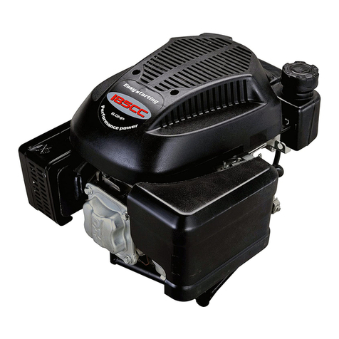
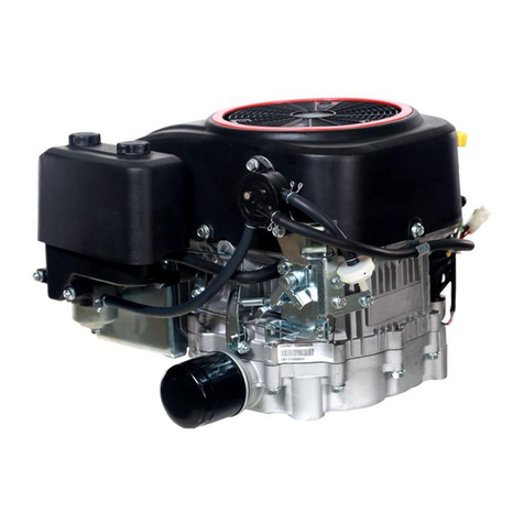
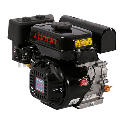
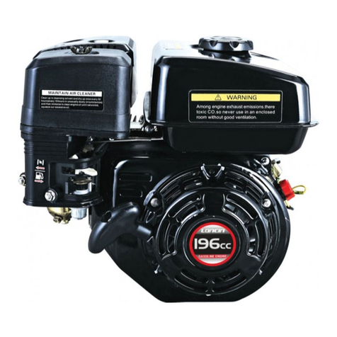
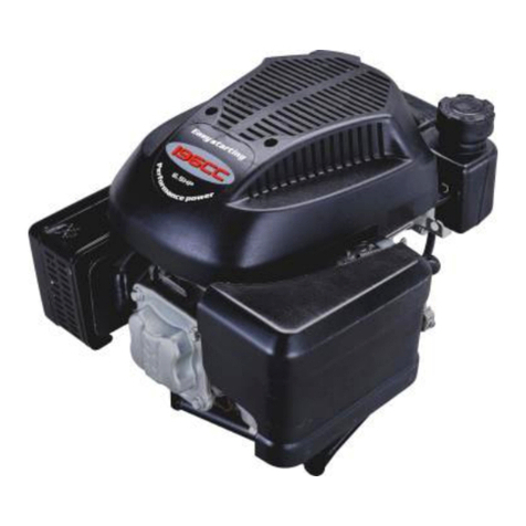
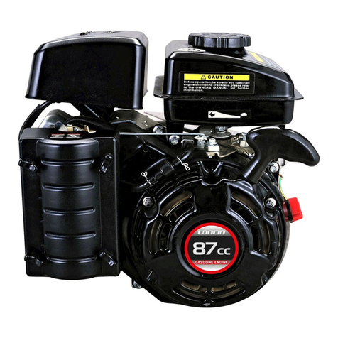
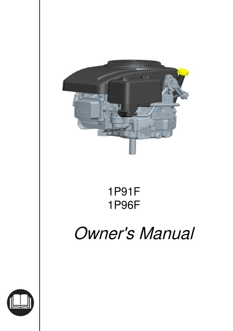
LONCIN LC2V80FD User manual

LC2V80FD
Maintenance Manual
LONCIN MOTOR CO., LTD.

SAFETY INFORMATION
Before operating
and maintaining the engine,
please carefully read and understand the
Maintenance Manual. To use the machine safely
and efficiently, you must conduct proper
maintenance and operation to the machine.
The following identifications throughout the
Manual may g
ive prompts to operators and
maintainers as well as illustrate matters that
cause dangers.
The identification reminds you to
note that it may cause severe personal injury or
death which is imperative.
The identification reminds you to
note that it may ca
use severe personal injury or
death or improper operation.
This identification reminds you to
note that it may cause personal injury or property
damage or improper operation.
Be vigilant to fuel oil, exhaust emissions and
moving parts to avoid severe perso
death.
Add fuel carefully!
● Gasoline is inflammable.
Please add the
fuel oil in the outdoor, well-
ventilated area after
the engine is stopped.
●
It is prohibited to smoke when adding
gasoline and be away from flame and spark.
● It is
prohibited to start the engine before the
gasoline splashed area is dry.
Heat Exhaust
●
The temperature of silencer can be very
high during the operation of engine; even if the
SAFETY INFORMATION
and maintaining the engine,
please carefully read and understand the
Maintenance Manual. To use the machine safely
and efficiently, you must conduct proper
maintenance and operation to the machine.
The following identifications throughout the
ive prompts to operators and
maintainers as well as illustrate matters that
The identification reminds you to
note that it may cause severe personal injury or
The identification reminds you to
use severe personal injury or
This identification reminds you to
note that it may cause personal injury or property
Be vigilant to fuel oil, exhaust emissions and
moving parts to avoid severe perso
nal injury or
Add fuel carefully!
Please add the
ventilated area after
It is prohibited to smoke when adding
gasoline and be away from flame and spark.
prohibited to start the engine before the
The temperature of silencer can be very
high during the operation of engine; even if the
machine is stopped for a moment, it would be
hot.
Be careful not to touch the
Prior to
maintenance, the engine shall be placed
indoor and cooled down.
●
To prevent fire, when the engine is working,
the distance between the engine and the wall
shall be kept at least 1 m.
away from the engine.
Carbon Monoxide Poisoning
●
The exhaust contains poisonous carbon
monoxide.
Avoid inhaling the exhaust.
● Don’t use indoors.
●
Don’t operate the engine in the closed
garage or enclosed area.
General Precautions
●
Carefully read the Maintenance Manual, g
familiar with all the
control
correct using and maintenance & installing
method of the machine and master the operating
method of stopping and fast separating the
machine.
●
When you feel fatigue, have discomfort or
have a drink, plea
se don’t operate the engine;
otherwise, it may cause severe injury.
●
Children and people who don’t read the
Manual or without training are prohibited to use
the engine.
●
Don’t repair the machine without mastering
the method of engine repair.
● Don’t refi
t the machine or change its
structure. Once the machine loses its balance, it
may easily cause damages and injury incidents.
machine is stopped for a moment, it would be
Be careful not to touch the
burning silencer.
maintenance, the engine shall be placed
To prevent fire, when the engine is working,
the distance between the engine and the wall
Inflammables must be
Carbon Monoxide Poisoning
The exhaust contains poisonous carbon
Avoid inhaling the exhaust.
Don’t operate the engine in the closed
General Precautions
Carefully read the Maintenance Manual, g
et
control
mechanisms and the
correct using and maintenance & installing
method of the machine and master the operating
method of stopping and fast separating the
When you feel fatigue, have discomfort or
se don’t operate the engine;
otherwise, it may cause severe injury.
Children and people who don’t read the
Manual or without training are prohibited to use
Don’t repair the machine without mastering
the method of engine repair.
t the machine or change its
structure. Once the machine loses its balance, it
may easily cause damages and injury incidents.

Contents
Part I Technical Specifications
1-1 Introduction of engine .................................................................................................................................... 1
1-2 Technical parameters ..................................................................................................................................... 3
1-3 Model installation dimensional drawing ........................................................................................................ 4
1-4 P.T.O dimensional drawing ........................................................................................................................... 7
1-5 Electric wiring diagram ................................................................................................................................. 9
Part II Repair Instructions
2-1 Maintenance precautions ............................................................................................................................. 10
2-2 Marking position of machine No. ................................................................................................................ 11
2-3 Maintenance standards ................................................................................................................................. 12
2-4 Torque parameters of fasteners .................................................................................................................... 13
Part III Maintenance
3-1 Maintenance schedule .................................................................................................................................. 15
3-2 Change engine oil ........................................................................................................................................ 16
3-3 Maintenance of air filter .............................................................................................................................. 18
3-4 Maintenance of silencer ............................................................................................................................... 19
3-5 Maintenance of spark plug ........................................................................................................................... 20
3-6 Adjustment of valve clearance ..................................................................................................................... 21
3-7 Adjustment of idle speed ............................................................................................................................. 21
3-8 Adjustment of speed regulator ..................................................................................................................... 22
3-9 Storage of engine ......................................................................................................................................... 23
Part IV Faults Diagnosis
4-1 Difficulty of engine in starting ..................................................................................................................... 25
4-2 Underpower of engine .................................................................................................................................. 26
4-3 Rotating speed instability of engine ............................................................................................................. 27
4-4 Abnormal exhaust colors of engine .............................................................................................................. 28
4-5 Engine is easily to be flameout .................................................................................................................... 29
4-6 Engine has no high speed ............................................................................................................................. 29
4-7 Overheat of engine ....................................................................................................................................... 30
4-8 Abnormal noises of engine ........................................................................................................................... 31
4-9 Fault of electric starting system ................................................................................................................... 32

Contents
4-10 Check the cylinder pressure ....................................................................................................................... 33
4-11 Detection of spark ...................................................................................................................................... 33
Part V Disassembly & Repair
5-1 Precautions on disassembly/assembly ......................................................................................................... 34
5-1-1 Disassembly .............................................................................................................................................. 34
5-1-2 Assembly .................................................................................................................................................. 34
5-2 Disassembly and maintenance of engine...................................................................................................... 35
5-2-1 Air filter .................................................................................................................................................... 35
5-2-2 Silencer ..................................................................................................................................................... 36
5-2-3 Fan cover - starting control switch ............................................................................................................ 37
5-2-4 Carburetor ................................................................................................................................................. 40
5-2-5 Speed-regulating mechanism .................................................................................................................... 43
5-2-6 Flywheel and ignition coil ........................................................................................................................ 44
5-2-7 Cylinder head and valve ........................................................................................................................... 47
5-2-8 Secondary oil filter, breather slot and air guide sleeve ............................................................................. 52
5-2-9 Crankcase, crankshaft and piston ............................................................................................................. 54

Part I Technical Specifications
- 1 -
1-1 Introduction of engine
Engine switch
Oil condenser
Secondary oil filter
Oil drain bolt
Throttle handle
Choke-valve
handles
Silencer
Spark plug cap
Fuel pump
Air filter

Part I Technical Specifications
- 2 -
Air filter - protect the engine through filtering dusts and impurities in the air.
Spark plug - input high voltage at ignition coil to the engine combustor, generate spark through
air discharge between electrodes and introduce combustion of mixed gases.
Silencer - a device to prevent the transmission of engine sound and reduce the noise of exhaust
system.
Fuel filter - filter impurities in the fuel through oil pipes between fuel tank and carburetor.
Oil condenser - pump the engine oil into it through the oil pump and enter the lubricating main oil
gallery after it is cooled down by the cooling fin.
Secondary oil filter - oil passes it to filter impurities and then enters the lubricating main oil
gallery.
Choke-valve handle - cold start the engine and close the choke valve, the carburetor would supply
concentrated mixed gas, which makes the engine to be easily started. After preheating the engine,
fully open the choke-valve handle.
Engine switch - before starting the engine, turn the switch to “ON” position; the engine can be
shut down when turning the switch to “OFF” position.
Throttle handle - turning throttle handle may adjust the rotating speed of the engine to achieve
the power and rotating speed expected.
Oil drain plug - swinging out drain plug may drain all the oil in the engine out so as to replace the
oil.

Part I Technical Specifications
- 3 -
1-2 Technical parameters
The rated power of the engine indicated in the Manual is the net output power (net power) at 3,600 rpm of an
engine under the production status measured in accordance with SAE J1349. For mass production engines, the
value may vary.
The actual power of engine installed on the terminal may vary in output, which depends on several factors
including the rotating speed of engine during practical use, environmental conditions, maintenance and other
variants.
Single-engine Power Unit Power
Type of Engine Double-cylinder, four-stroke-cycle, forced-
air cooling and overhead
valve
Air displacement
(diameter of cylinder × stroke) 764ml(80mmX76mm)
Maximum power
(kW/3600rpm) 19
Maximum torque (N·m)
Corresponding rotating speed (rpm)
52/2800
Fuel consumption rate
(g/kW·h) ≤ 350
Idle speed
(rpm) 1,800±150
Speed fluctuation rate ≤ 10%
Compression ratio 8.7:1
Starting mode Electronic start
Direction of rotation Anticlockwise (output terminal)
Valve clearance (mm)
Inlet valve 0.10 ~ 0.15
Exhaust valve 0.15 ~ 0.20
Spark plug RC12YC
Spark plug gap (mm) 0.7 ~ 0.8
Ignition mode Transistorized magneto ignition
Type of air filter Double filter cartridge
External dimensions (mm)
L × W × H 507×502×690 507×502×500
Net weight (kg) 50 49

Part I Technical Specifications
- 4 -
1-3 Model installation dimensional drawing
Unit power

Part I Technical Specifications
- 5 -
Single-engine power

Part I Technical Specifications
- 6 -
Crankcase cover interface dimensions
Mounting size of base

Part I Technical Specifications
- 7 -
1-4 P.T.O dimensional drawing
A 轴/Type A
B轴/Type B

Part I Technical Specifications
- 8 -
C轴/Type C

Part I Technical Specifications
- 9 -
1-5 Electric wiring diagram

Part II Repair Instructions
2-1 Maintenance Precautions
1. Use pure LONCIN parts or the specified parts and
lubricating oil.
Parts not meeting LONCIN’s
design specifications may damage the device or
the engine.
2.
Operations requiring special tools must be
completed with special tools and corresponding
devices.
3. The washer, gasket, O-
ring, oil seal, etc. shall be
replaced after being dismantled.
4. When fastening bolts, nuts and screws, fasten
them in an order from larger diameter to smaller
one and from inside to outside in a crossing way
to the specified torque.
Part II Repair Instructions
- 10 -
1. Use pure LONCIN parts or the specified parts and
Parts not meeting LONCIN’s
design specifications may damage the device or
Operations requiring special tools must be
completed with special tools and corresponding
ring, oil seal, etc. shall be
4. When fastening bolts, nuts and screws, fasten
them in an order from larger diameter to smaller
one and from inside to outside in a crossing way
5. Parts shall be cleaned after being dismantled and
shall be coated with oil on the sliding surface
during assembly.
6. Fastening places and action status must be checked
after the assembly.
7. The engine shall be shut down when it is under
check and maintenance.
after the engine is completely cooled down.
Operation in high temperature
cause accidents such as burning injuries.
8. After maintenance, if it needs to carry out running
test on the operation site, please note full
ventilation.
In addition, fire must be prohibited
near inflammables such as fuel an
5. Parts shall be cleaned after being dismantled and
shall be coated with oil on the sliding surface
6. Fastening places and action status must be checked
7. The engine shall be shut down when it is under
check and maintenance.
Operation shall be done
after the engine is completely cooled down.
Operation in high temperature
of the engine may
cause accidents such as burning injuries.
8. After maintenance, if it needs to carry out running
test on the operation site, please note full
In addition, fire must be prohibited
near inflammables such as fuel an
d grease.

Part II Repair Instructions
- 11 -
Follow up the guidance indicated by the signs below:
Coat oil at the
indicated
position.
Operate with
special tools.
Coat grease at the
indicated
position.
○×○(○): the mode, length and quantity of flange bolt.
P.: the page shall be referred to.
2-2 Marking position of machine No.
Machine No. is marked on the crankcase as shown in the figure below. When LONCIN dealers
require correct parts during maintenance, the machine number is used to check the engine or to order
parts.
Engine No.:
TXXXXX XX XX XXXXXXX
Serial no.
Production month
Production year
Development order no.
Marking position
of machine No.

Part II Repair Instructions
- 12 -
2-3 Maintenance standards
Unspecified unit: mm
Parts Item
LC2V80FD
Standard Maintenance limit
Engine Compression pressure (kgf/cm2)* 11-13 -
Air cylinder Inner diameter of cylinder liner 80-80.01 80.15
Piston
Outer diameter of skirt 79.965-79.975 79.755
Clearance to the air cylinder 0.025~0.045 0.255
Inner diameter of piston pin hole 17.002~17.008 17.12
Clearance between the piston pin and
piston pin hole 0.004~0.016 0.029
Piston pin Outer diameter 16.992~16.998 16.9
Piston ring
Clearance to the side of the piston ring
(gas ring 1 / gas ring 2) 0.02~0.06 0.11
Clearance to the side of the piston ring
oil ring 0.03~0.08 0.15
Clearance to the end of the piston ring
gas ring 1 0.20~0.40 0.7
Clearance to the end of the piston ring
gas ring 2 0.30~0.50 0.8
Clearance to the end of the piston ring
oil ring 0.20~0.70 1.0
Width of ring (gas ring 1) 2.90 2.77
Width of ring (gas ring 2) 3.30 3.17
Width of ring (oil ring) 2.60 2.07
Connecting rod
Inner diameter of the small end 17.006~17.017 17.05
Inner diameter of the big end 40.015~40.025 40.065
Oil-film clearance of the big end 0.024-0.059 0.115
Side clearance of the big end 0.203~0.403 1.0
Crankshaft Outer diameter of the crankshaft journal
(big end of the connecting rod) 39.966~39.991 39.906
Valve
Valve clearance (cold) Inlet 0.10~0.15 -
Valve clearance (cold) Exhaust 0. 15~0.20 -
Outer diameter of valve stem Inlet 6.565~6.58 6.438
Outer diameter of valve stem Exhaust
6.545~6.56 6.435
Valve guide
Inner diameter of valve guide Inlet &
exhaust 6.6~6.615 6.672
Clearance between valve stem and
valve guide Inlet 0.02~0.05 0.15
Clearance between the valve stem and
valve guide Exhaust 0.04~0.07 0.17
Valve seat Contact width of valve seat 0.7~0.8 2.0
Valve spring Free length 39.5~40.5 39
Camshaft Cam height Inlet 29.95~30.05 29.75
Cam height Exhaust 29.95~30.05 29.75

Part II Repair Instructions
- 13 -
Outer diameter (bearing position) 15.966~15.984 15.916
Crankcase cover
Inner diameter of camshaft hole 16~16.018 16.068
Spark plug Electrode clearance 0.7-0.8 -
Spark plug cap Resistance 10kΩ -
Ignition coil
Resistance value Primary side 1-1.4Ω -
Resistance value Secondary side 6.2-7.6Ω -
Clearance to the flywheel 0.3~0.4 -
2-4 Torque parameters of fasteners
(1) Torque parameters of parts
Fastening Item Specification of Thread Fastening Torque (N.m)
Fastening bolt of connecting rod M6×1 11-13
Fastening bolt of cylinder head M10×1.25 50-55
Fastening bolt of flywheel M12×1.25 80-100
Fastening bolt of crankcase cover M8 × 1.25 25-30
Seal screw plug (crankcase-body oil
drain plug) M14 × 1.5 30-35
Valve adjusting bolt M8×1.25 28-32
Valve lock nut M6×0.75 12-16
Fastening bolt of cylinder-head-cover
M6 × 1 8-12
Fastening bolt of breather slot cover
plate M6 × 1 8-12
Oil pipe connection of radiator M10 × 1 20-25
Mounting bolt for secondary oil filter
M20 × 1.5 40-45
Secondary oil filter 3/4-16UNF 10-13
Fastening nut of speed-regulating
support M6 × 1 8-10
Fastening bolt of starting motor M8 × 1.25 22-28
Spark plug 25-30
Note: for unspecified bolts and nuts in the above mentioned table, please refer to standard torques.

Part II Repair Instructions
- 14 -
(2) Standard torque parameters
Fastening Parts Specification of Thread Torque (N.m)
Bolt and nut
5 mm Bolt and nut 4-7
6 mm Bolt and nut 8-12
8 mm Bolt and nut 20-28
10 mm Bolt and nut 35-40
12 mm Bolt and nut 50-60

Part III Maintenance
- 15 -
3-1 Table of maintenance periods
Periodic Maintenance Schedule Time
of Use
20 H or the
first Month
of Initial Use
50 H or
Every 3
Months
100 H or
Every 6
Months
300 H or
Every
Year
Engine oil
Check the oil
level ○
Replacement ○ ○
Secondary oil
filter Replacement ○(2) 200 h
Air filter
Check ○
Clear ○(1)
Replacement ○(3)
Fuel filter Replacement ○(1)
Position of
battery
electrolyte
Check ○
Spark plug
Check and
adjust the
clearance
○(2)
Replacement ○
Valve
clearance
Check and
adjust the
clearance
○(2)
Oil pipe Replacement Every 2 years (2)
○ Maintenance matters
(1) Maintenance intervals shall be shortened when it is used in a place full of dusts.
(2) Unless users have professional repair tools and maintenance skills, or these projects shall be
assisted and maintained by franchised dealers of LONCIN.
(3) Only replace foam and paper filter cartridge
Under circumstances of frequent use, long-term use can only be guaranteed through maintenance
with correct intervals specified above.

Part III Maintenance
- 16 -
3-2 Change engine oil
Note: drain engine oil when the machine is stopped but not cooled down so as to guarantee the fast and
thorough exhaust of the oil.
The engine oil of gasoline is the main factor that affects the
performance and life of gasoline. Suggest not using engine
oil containing additive substance and two-stroke engine oil
as they are lack of lubrication, which may shorten the service
life of the gasoline.
When checking the engine oil, shut down the machine and
place it on a horizontal plane.
Capacity for engine oil:
Without replacement of secondary oil filter: 1.6 L
With replacement of secondary oil filter: 1.8 L
To make the engine achieve its ideal operating effect, it is
suggested to use the qualified and dedicated engine oil of
LONCIN.
Recommended engine oil:
4-stroke gasoline engine oil.
API-classified SE, SF or equivalent to SG grade’s SAE 10W-30.
You can use engine oil in other viscosity when the local
temperature is within the scope as shown in the figure.
Check steps:
1) Remove the oil level gauge and wipe out the engine oil.
2) Insert the oil level gauge into the oil-filling hole but do
not screw it up, then check the oil level.
3) If the oil level is too low, fill the recommended engine
till it reaches the upper limits indicated by the oil level gauge.
4) Re-install the oil level gauge.
Ambient
temperature
Gasket
Oil drain plug
Oil level
gauge
Oil plug
Oil filling
port
Maximum
oil level
Minimum
oil level
Table of contents
Other LONCIN Engine manuals

LONCIN
LONCIN 1P61FA User manual

LONCIN
LONCIN 1P91F User manual

LONCIN
LONCIN LC154f-1 User manual

LONCIN
LONCIN LC1P85FA User manual

LONCIN
LONCIN LC2V78 User manual

LONCIN
LONCIN 160F User manual

LONCIN
LONCIN 2V90FD User manual

LONCIN
LONCIN LC1P88F-1 User manual

LONCIN
LONCIN LC178FD User manual

LONCIN
LONCIN LC170F User manual