LPG CELLU M6 Alliance Medical User manual

GU1601-EN
Indice B 09/2020
OPERATOR’S MANUAL
Registered design
Please read the complete manual carefully
before using your equipment.
© Copyright 2020. LPG®, Cellu M6®, EndermowearTM and Endermologie®are registered trademarks
of LPG SYSTEMS and/or trademarks on which it holds exclusive rights.
Reproduction, even in part, is strictly prohibited.
CELLU M6 Alliance®Medical

1
In order to respond better to customer requirements and expectations, LPG Systems is continuously
researching ways of improving the design and quality of its products. This will explain the few minor
differences between your equipment and the item described in this guide.
≥ATTENTION
Congratulations on the purchase of your CELLU M6 Alliance®Medical device.
This model represents many years of research in the design and production
of cutaneous tissue treatment systems. You will be able to fully appreciate the
technical perfection and reliability that have made LPG Systems the leader in this
field.
With the aim to continuously provide satisfaction, your device is equipped with a
specific software devised to ensure connection with the LPG Systems dedicated
server. The data collected through this software will allow LPG Systems to give
you better services in respect of support and maintenance.
This operator’s manual contains the operating description, basic maintenance
instructions to be performed periodically and the safety instructions.
Your device is intended for use in the treatment of connective tissue. It should be
used only by a professional who has attended the manufacturer’s training provided
by LPG Systems or an official distributor if you live outside of France.
If you have any doubts whatsoever concerning the operation or maintenance of
your equipment, please do not hesitate to contact LPG Systems via the Customer
Service Department of your distributor.
+33 (0)4 75 78 69 00

2
Unpackaging instructions to be retained.
≥ATTENTION
> PACKAGE CONTENTS
>One CELLU M6 Alliance®Medical device
> One Alliance 80 treatment head
> One Alliance 50 treatment head
> One TR30 treatment head
> One set of micro-nozzles and micro-heads
> One Ergolift®treatment head
> Two Ergolift®chamber (Lift20 and Lift10)
> One electrical power cord
> One unpackaging instructions and quick installation guide
> One marketing set

3
Depending on the version you have, (see serial number on the nameplate), some
protocols are not activated and their accessories are not provided.
Accordingly, the paragraphs describing them do not concern this version (see table
below).
In any doubt about the operation of your unit or to evolve into a complete model, please
contact the Customer Service of LPG Systems or your distributor.
List of accessories provided with your device:
Cellu M6 Alliance®
Medical
Cellu M6 Alliance®
Medical Plus
Cellu M6 Alliance®
Medical Premium
Alliance 80 √ √ √
Alliance 50 √ √
TR30 √ √
Micro-nozzles
and micro-heads √ √
Ergolift
Unpackaging
instructions and
quick installation
guide
√ √ √
Cord √ √ √
Marketing set √ √ √

4
The manufacturer reserves the right to amend the product technical specifications without prior
notice. Any reproduction – even in part – is prohibited. All the illustrations in this operator’s manual
are non-binding.
≥ATTENTION
> TABLE OF CONTENTS
1. DEVICE DESCRIPTION .......................5
2. CONTROLS DESCRIPTION .....................7
3. IMPORTANT SAFETY INFORMATION ..............10
4. MAINTENANCE ..........................14
5. TROUBLESHOOTING .......................22
6. TECHNICAL SPECIFICATIONS
..................23
7. TREATMENT HEADS .......................24
8. ENDERMOWEAR .........................39
9. GENERAL WARRANTY CONDITIONS...............40
10. APPENDIX: ELECTROMAGNETIC COMPATIBILITY .......44

5
> DEVICE DESCRIPTION
DEVICE DESCRIPTION
1
INTENTED USE
The CELU M6 Alliance®Medical device is intended for therapeutic use. It can be used to:
1. Reduce secondary lymphedema of the arm after a mastectomy
2. Improve secondary lymphedema
3. Improve lymphatic circulation in the treated area
4. Relieve minor muscle aches and pains
5. Relieve muscle spasms
6. Temporarily improve local blood circulation
7. Temporarily relieve minor muscular pain associated with DOMS
(Delayed Onset Muscle Soreness)
8. Improve local circulation during burn rehabilitation
9. Reduce the appearance of cellulite and the circumference of treated areas
10. Temporarily improve lymphatic circulation and local blood circulation to improve skin
trophicity in the treated areas
11. Improve skin quality, scars, fibrosis
12. Improve skin aging (wrinkles, fine lines, skin sagging, fat infiltration, firmness,
elasticity, complexion and eye bags)
13. Stimulatie fibroblasts (collagen, elastin and hyaluronic acid synthesis)
The device can be used in hospitals, therapy centers and institutions by specialists and
physiotherapists. It can be used on adult patients only, of any weight or any sex. It is an
independent device that cannot be combined with other machines. It is to be used by
professionals who are specially trained by LPG Systems in the use of the device and is
not suitable for home use.
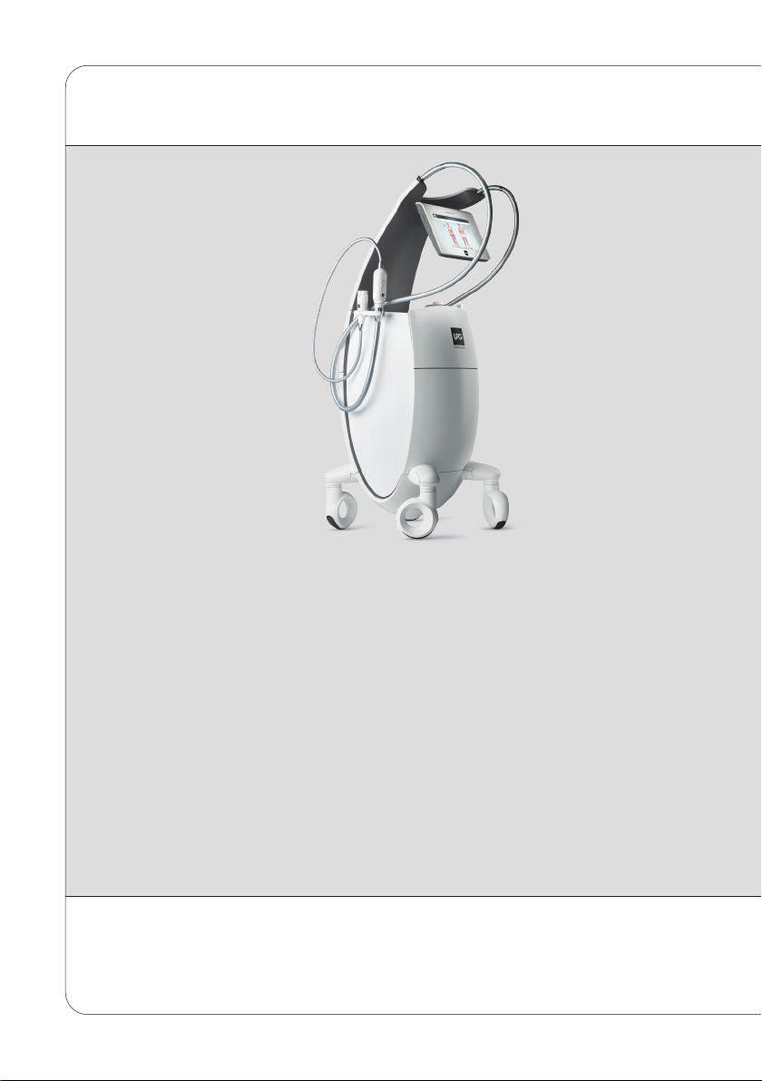
OPERATING PRINCIPLES:
The operating principles of the CELLU M6 Alliance®Medical device consist of a suction
force coupled with movements of rolls/valves, performed with treatment heads. These
heads are placed on the healthy skin of the patient and then moved across the area to be
treated by the professional who has been trained by LPG Systems.

6
The unit can only operate if it is connected to the power supply by its power cord and provided the
ON switch has been actuated and the green voltage light is on. After switching on the unit, please
wait a few seconds for the screen to display information.
≥ATTENTION
DEVICE DESCRIPTION
1> THE CELLU M6 ALLIANCE®MEDICAL DEVICE
CASTER LOCKING
MECHANISM
LEFT HOSE
FORWARDFACING
TOUCHSCREEN
HEAD HOLDER
IDENTIFICATION
PLATE
FILTER ACCESS DOOR
POWER SWITCH, SOCKET,
AND POWER INDICATION
Before use, ensure that the power cord is completely unwound.
RIGHT HOSE
HEAD HOLDER
HEAD STORAGE
DRAWER
HEAD STORAGE TRAY
CASTERS

7
For detailed instructions on using the touch interface, refer to the touch interface operating manual
received during training and available from customer service.
≥ATTENTION
> FILTER ACCESS
CONTROLS DESCRIPTION
2
> CONTROL SCREEN
LEFT HOSE FILTER
RIGHT HOSE FILTER
FILTER ACCESS
The filters are accessible via
the back of the unit.
POWER INDICATOR
TOUCHSCREEN
USB PORT ACCES

8
> ALLIANCE 80 HEAD
2
> ALLIANCE 50 AND TR30 HEADS
CONTROLS DESCRIPTION
PARAMETER SETTING
BUTTONS
EMBELLISHER FLAP
BRIGHT LEDS
ADJUSTEMENT SLIDER POSITION
ROLLER AND FLAP
MOTORISED ROLLER AND FLAP
PARAMETER SETTING
BUTTONS
EMBELLISHER FLAP
MOTORISED ROLLER AND FLAP
ADJUSTEMENT SLIDER
POSITION ROLLER
AND FLAP
ALLIANCE 50 TR 30
SEALING FLAP
MOTORISED ROLLER
ADJUSTMENT SLIDER
POSITION ROLLER

9
In cases where the unit has not been moved for a long time, it is possible that marks may form on
the ground where the casters are. This phenomenon is the result of a chemical reaction between the
components of some floorings and those of the wheels of the CELLU M6 Alliance®Medical device.
≥ATTENTION
> ERGOLIFT HEAD ADAPTER
> CASTERS
2
CONTROLS DESCRIPTION
SELECTION BUTTON FOR TREATMENT TYPE
POWER INCREASE BUTTON
POWER DECREASE BUTTON
ON/OFF BUTTON
HOSE CONNECTION
ERGOLIFT CHAMBER CONNECTION
They can be connected and disconnected
by a simple push-pull action.
UNLOCKED TO LOCK LOCKED
The CELLU M6 Alliance®Medical device is equipped with locking casters.
Please follow the procedure indicated below to lock or unlock the casters:

1010
Any serious incident occurring with your device should be reported to your local LPG distributor and competent authority.
> IMPORTANT SAFETY INFORMATION
IMPORTANT SAFETY INFORMATION
3
> WARNING
All safety precautions must be observed while using electrical equipment. Please read all
safety notices and precautions prior to use of the device.
≥ATTENTION
• Always disconnect the device from the
electrical supply outlet after use and before
cleaning and maintenance.
• Check that the supply voltage of the unit
indicated on the data plate complies with the
power supply voltage.
• The unit must be connected by the power
cord1supplied to a grounded outlet in
accordance with current electrical standards.
Electrical adapters must not be used with this
equipment.
• Ensure that the unit is connected to a
system with a differential protection
against DC and AC.
DANGER - TO MINIMISE THE RISK OF ELECTRICAL SHOCK:
• TO MINIMISE THE RISK OF BURNS, FIRE,
ELECTRICAL SHOCK OR INJURY:
• The device must not be left unattended while
connected to the electrical supply.
• Disconnect the unit from the electrical
supply if it is not going to be used for a
long period.
• Special attention is required while using the
device with, or in the proximity of children or
disabled persons.
• Never use the unit for purposes other than
those recommended by LPG Systems. Only
use the treatment heads supplied with your
unit or recommended by LPG Systems.
• Never use the device if:
The electrical power cord or outlet is
damaged. The device does not function
correctly. The device is damaged or has
fallen or been dropped. The device has been
exposed to excessive humidity.
• Do not move the unit by pulling the electrical
power cord.
• Fully unwind the electrical power cord and
keep it away from warm surfaces.
• Never use the device if the ventilation ports
are obstructed. Ensure that the ventilation
ports are kept clear of dust or other
contaminants.
• Do not allow solid debris, liquid or other
foreign bodies to fall or be sucked into the
unit, as these could cause damage.

11
Europe VII-H05VVF3G1,50-C19; Italy I/3/16-H05VVF3G1,50-C19; Switzerland 23G-H05VVF3G1.50-C19; UK
BS13/13-H05VVF3G1,50-C19; Japan 498GJ-VCTF3X2.00-C19; USA, Canada, Mexico N5/15-SJT3X14AWG-C19
(connect to Hospital grade receptacle in hospital environnement).
IMPORTANT SAFETY INFORMATION
3
> SAFETY INFORMATION
> IMPORTANT SAFETY INFORMATION
• Never touch the patient and the device’s
unprotected cables or connectors simultaneously.
• Never use the adapter as a treatment head or
allow it to come into direct contact with the skin.
• Only use treatment heads supplied with your unit
or recommended by LPG Systems.
• Do not use the treatment heads directly on the
skin. Wear the treatment suit provided by LPG
Systems, ENDERMOWEARTM.
• LPG Systems will not be liable for any
inappropriate use of the equipment.
• Improper use of the device can cause tissue
damage or pain.
• The operator must be particularly attentive to
the sensations felt by the person undergoing
treatment.
• The operator must ensure that the parameters
(intensity, sequentiality, differential, etc.) are
always adapted to the tissue being treated.
• Do not lean, rest or sit on the unit.
• When crossing a threshold or step, we
recommend moving the unit carefully by firmly
holding the central arm monitor stand to avoid
the risk of tipping.
• Do not use the USB connection during treatment.
• Do not operate the unit in unsuitable
environmental conditions (see technical
specifications).
• The power plug is used as disconnect device.
The disconnection of the unit is possible by
disconnecting the power plug.
• Please position your device so that the power
supply unit is always accessible.
• Do not touch the patient and the hose connectors
simultaneous.
• Do not use vegetable oil on the treatment heads.
≥ATTENTION
• Never use the device on a dusty, uneven floor
or in a moist atmosphere.
• Never use the device in the presence
of aerosols or oxygen.
• Before disconnecting the unit from the
electrical supply, set all controls to the
‘off’ position and unplug the unit. The
disconnection of the unit is disconnecting
the power plug.
• It is prohibited to modify this equipment
without prior authorisation from the
manufacturer.
• It is prohibited to use components or spare
parts non recommended by LPG Systems.
• Return the device to LPG Systems Service
Center for examination and repair.
ATTENTION: KEEP THESE INSTRUCTIONS.
Your device should be used on healthy skin. It is important to read and respect the following
precautions and contraindications before using your device.

12
This unit contains programs to help the operator obtain the best anticipated results for each case
undergoing treatment. Under no circumstances may these programs be construed as a guarantee of
successful treatment, which varies depending on the morphology, physiology and eating behaviour of
each patient.
≥ATTENTION
> CONTRAINDICATIONS
3
IMPORTANT SAFETY INFORMATION
• Do not treat open wounds, eyes, intracavity
areas, mucous membranes, genitals or
nipples.
• This device is not recommended for pregnant
women. In the event of pregnancy, do not
treat the lumbar-abdominal region. Consult
with a doctor regarding this treatment.
• Do not treat a patient with an infectious
disease, a growing tumour, a phlebitis, a
wound or an infected area.
• Do not treat a patient with skin cancer, a
visible tumour or other cancerous lesions.
Consult with a doctor in cases where the
patient has a case history of tumours or is in
remission.
• Do not treat inflammatory areas or scars
without medical advice and LPG technical
training for the affected areas.
• Do not treat patients with circulatory
problems without first consulting their
doctor and without LPG Technical training
for the affected areas.
• Do not treat a patient with an unexplained
and persistent pain without medical advice
and without LPG technical training for the
affected areas.
• Do not treat a patient after an invasive
medical treatment without medical advice or
the surgeon who carried out the treatment
and without training in LPG device for the
affected areas.
• To avoid bruising, exercise caution
when determining a patient’s level of
sensitivity and avoid use on patients taking
anticoagulant drugs.
• Stop treatment immediately if the patient
experiences pain and consult a doctor.
• This device should not be used on
all dermatoses, skin rashes, herpes,
inflammatory or infectious acne or vitiligo.
• Because of the risk of interference, it is
important that the professional ensures
the patient is not equipped with a personal
medical device such as a pacemaker. If this
is the case, the professional should obtain
details about the device in question to ensure
that any interference will not affect the
correct use of the equipment.
• As this list is not exhaustive, always seek out
medical advice in the event of doubt.
• For a more detailed list of contraindications
and against indications, refer to training
manuals.

13
> ELECTROMAGNETIC COMPATIBILITY
IMPORTANT SAFETY INFORMATION
3
• Your CELLU M6 Alliance®Medical device requires special care concerning the EMC; it must be
installed and serviced according to the information provided in this user guide.
• Portable and mobile RF communication devices must not be used within 30 cm of your device;
they can cause undesired operation.
• The use of treatment heads other than those provided by LPG may result in increased
emissions or decreased immunity of the device.
• Your CELLU M6 Alliance®Medical device should not be used adjacent to or stacked with other
medical devices.
• The Cellu M6 Alliance®Lab Medical device does not manage essential performances.
• Interference may occur near equipment marked with the following symbol:
For more information about electromagnetic compatibility, refer to the “Electromagnetic
Compatibility” appendix.

14
The identification rating plate is located on the underside, at the back of the unit. Identification rating
plates may vary. The approved one is one on your machine.
≥ATTENTION
MAINTENANCE
4> IDENTIFICATION RATING PLATE
Your unit is identified by a serial number
shown on the rating plate. The rating plate
also shows the permitted supply voltage
for the unit. If you need to contact LPG
Systems because of a technical problem,
please indicate the serial number of your
Cellu M6 Alliance® Medical device. This
serial number provides information on the
year and month of manufacture of your unit.
The letter indicates the year the device was
manufactured. Z=2009, A=2010, B=2011, etc.
The two digits indicate the production month:
01=January; 02=February; 03=March; etc.
serial
number
voltage, frequency
and power
This icon indicates that the unit was sold
after August 13, 2006. In conformity with the
2002/96/CE directive, it cannot be thrown away
with standard household waste but must be
disposed of by means of recycling. When your
device reaches the end of its useful life, it
must be brought to an appropriate recycling
centre or returned to your dealer. By doing so,
you help the environment by contributing to
the conservation of natural resources and the
protection of human health.
This icon indicates that some specific warnings
or precautions associated with
this device are not on the label.
This symbol means you must consult the
accompanying documents before using
your device.
This symbol indicates the name and address of
the manufacturer.
This symbol means that your device has type
BF applied parts which come into contact with
the patient. These parts are electrically isolated
from all of the device’s other parts. These
applied parts are the treatment heads.
This symbol means store the device somewhere
protected from inclement weather.
This symbol indicates temperature limits.
This symbol indicates the weight of the
device.
This symbol indicates relative
humidity limits.
This symbol means
“Do not push.”
This symbol means
“Danger: High Voltage.”
This symbol means
“Use under prescription” (US only).
This symbol indicates the year of the
manufacturing.
This symbol means
“Fragile, handle with care.”
This symbol indicates to not
reverse the device.
This symbol indicates to keep
the device up right.
This symbol indicates atmospheric
pressure limits.

15
Proscribe aggressive products such as acetone, trichlorethylene or alcohol at 90°.
≥ATTENTION
MAINTENANCE
4
> CLEANING THE UNIT
It is recommended that you clean your unit as often as possible, not only for hygienic and
aesthetic reasons, but also because cleaning the unit will help keep it in a good state of
repair and extend its useful life.
Using a vacuum cleaner with a fine nozzle, clean the following sections:
• Interior of the head storage drawer.
• Interior of the head storage tray.
• Interior of the filter access door.
Using a moist sponge, clean the following sections:
• All the external hoods.
• Hoses.
• The electrical power cord.
Using a cloth soaked with a small amount of alcohol-free domestic cleaning product, clean
the following sections:
• Control screen and control panel.
• Interior of the head storage drawer.
• Interior of the head storage tray.
• Interior of the filter access door.
Using an antistatic cloth or wipes, clean:
• The touchscreen.
The maintenance of the treatment heads should be performed before the first use. See
chapter “Treatment heads”.

16
≥ATTENTION
MAINTENANCE
4> REPLACING THE FILTER CARTRIDGES AND FOAM
The device must never be used without a filter. If no filter is fitted, the device must be switched off.
Your device contains two filter cartridges and one filter foam.
These components guarantee the efficiency of your unit and prolong its useful life.
FIG. 5
FIG. 4
FIG. 1
FIG. 3
FIG. 2
Ensure that they are changed as
soon as the icon indicating a filter
change appears on the screen
(Fig. 1),
Access the ‘filter change’ menu
as follows:
Select the ‘maintenance’ menu by
pressing the icon indicated (Fig. 2).
Select the ‘filter’ menu by pressing
the icon indicated (Fig. 3).
The ‘filter change’ screen indicates
which filter requires changing
(Fig. 4).
Once the filter cartridge is
replaced, the filter meter should
be reset by pressing the icon
indicated (Fig.5).
PRESS THIS ICON

17
MAINTENANCE
4
1. Open the filter access door
(Fig. 1).
2-3. Unscrew and remove the filter
cartridges and replace them with
new ones (Fig. 2 and Fig. 3).
4. Remove the filter foam and
replace it with a new one
(Fig. 4 and Fig. 5).
Remember to purchase new filter
cartridges from the LPG Systems
Customer Service Department so
you always have a spare
.
FIG. 1 FIG. 2
FIG. 3 FIG. 4 FIG. 5
Replace the filter cartridges as follows:
> REPLACING THE FILTER CARTRIDGES AND FOAM

18
> CONNECTING/DISCONNECTING
THE MOTORISED TREATMENT HEADS
MAINTENANCE
4
FIG. 2
FIG. 4 FIG. 5
To connect the heads to the hose, follow the
procedure below.
Position the locking ring in the locked position
(Fig.1).
Position the end of the hose so that the hose key
is lined-up with the key slot of the treatment head
connection (Fig.2).
Push the hose into the treatment head connection
until it cliks into place.
FIG. 3
FIG. 1
LOCKING RING
ORNAMENTAL
RING
LOCKED
POSITION HOSE KEY
KEY
SLOT
To disconnect the heads to the hose, follow the procedure below.
Position the locking ring in the unlocked position (Fig.3).
Pull the locking ring towards the hose (Fig.4).
Carefully remove the hose by pulling it by the white ring (Fig.5).
UNLOCKED
POSITION
UNLOCKED LOCKED

19
MAINTENANCE
4
> CONNECTING / DISCONNECTING THE ADAPTER
ADAPTER CONNECTION MICROHEADS AND
MICRONOZZLES CONNECTION
To connect or disconnect the hose
adapter, follow the procedures
described in chapter 4.4 “Connecting/
Disconnecting the motorised treatment
heads.
The connection is made with a simple
push/pull movement.
HOSE CONNECTION
TREATMENT HEAD
CONNECTION
HOSE KEY
Only the micro-heads and the micro-nozzles can be connected to the adapter.
The connection is made with a simple push/pull movement.
Other manuals for CELLU M6 Alliance Medical
1
This manual suits for next models
2
Table of contents
Other LPG Medical Equipment manuals

LPG
LPG CELLU M6 Alliance Medical User manual

LPG
LPG Cellu M6 Endermolab i User manual

LPG
LPG HUBER 360 EVOLUTION User manual

LPG
LPG HUBER 360 EVOLUTION User manual

LPG
LPG Cellu M6 Alliance Technical manual

LPG
LPG HUBER 360 EVOLUTION User manual

LPG
LPG Mobilift M6 Connect User manual

LPG
LPG CELLU M6 Alliance Lab Medical User manual

LPG
LPG Cellu M6 Alliance User manual

LPG
LPG Cellu M6 User manual