LPG CELLU M6 Alliance Medical User manual

1
In order to respond better to customer requirements and expectations, LPG Systems is continuously
researching ways of improving the design and quality of its products. This will explain the few minor
differences between your equipment and the item described in this guide.
≥ATTENTION
GU1601-EN
Edition A1 - 01/18
OPERATOR’S MANUAL
Registered trademark
Congratulations on the purchase of your CELLU M6® Alliance Medical. This model
represents the fruits of numerous years of experience in the design and production
of cutaneous tissue treatment systems. You will experience fully the technical
perfection and reliability of LPG Systems, which is the leader in this sector.
With the aim to continuously provide satisfaction, your device is equipped with
a specific software devised to ensure connection with the LPG dedicated server.
The data collected through this software will allow LPG to give you better services
in respect of support and maintenance.
This operator’s manual contains the operating description, basic maintenance
instructions to be performed periodically and the safety instructions.
Your device is intended for use in the treatment of connective tissue. It should be
used only by a professional who has attended the manufacturer’s training provided
by LPG Systems or an approved provider, if you live outside of France.
If you have any doubts whatsoever concerning the operation or maintenance of
your equipment, please do not hesitate to contact LPG via the Customer Service
Department of your distributor.
+33 (0)4 75 78 69 00
Please read the complete manual carefully
before using your equipement.
© Copyright 2016. LPG, CELLU M6 and Alliance are registered trademarks of LPG.
Reproduction, even in part, is strictly prohibited.
CELLU M6® Alliance Medical

2 3
Unpackaging instructions to be retained.
≥ATTENTION
> PACKAGE CONTENTS
> One CELLU M6® Alliance Medical device
> One Alliance 80 head
> One Alliance 50 head
> One TR30 head
> One set of micro-nozzles and micro-heads
> One Ergolift® head
> Two Ergolift® chamber (Lift20 and Lift10)
> One electrical power cord
> One unpackaging instructions and quick installation guide
> One marketing set
Pack
body
Pack
face
Pack
therapeutic
Pack
aesthetical
medicine
Pack
spa
Alliance 80 √
Alliance 50 √ √ √
TR30 √ √ √
Micro-nozzles
et micro-heads √ √
Ergolift √ √ √
Ergolift chamber
(Lift 10, Lift 20) √ √ √
Unpackaging
instructions and
quick installation
guide
√ √ √ √ √
Cord √ √ √ √ √
Marketing set √ √ √ √ √
Depending on the version you have, (see serial number on the nameplate), some
protocols are not activated and their accessories are not provided.
Accordingly, the paragraphs describing them do not concern this version (see table
below).
In any doubt about the operation of your unit or to evolve into a complete model, please
contact the Customer Service of LPG Systems or your distributor.
Liste of accessories provided with your device :

54
The manufacturer reserves the right to amend the product technical specifications without prior
notice. Any reproduction – even in part – is prohibited. All the illustrations in this operator’s manual
are non-binding.
≥ATTENTION
> DESCRIPTION OF THE DEVICE
DESCRIPTION OF THE DEVICE
1
> SOMMAIRE
INTENTED USE
The CELU M6® Alliance Medical device is intended for therapeutic use. It can be used to :
1. Reduce secondary lymphedema of the arm after a mastectomy
2. Improve secondary lymphedema
3. Improve lymphatic circulation in the treated area
4. Relief of minor muscle aches and pains
5. Relieve muscle spasms
6. Temporary improvement in local blood circulation
7. Temporary relief of the minor muscular pain associated with DOMS
(Delayed Onset Muscle Soreness)
8. Improves local circulation during burn rehabilitation
The machine can be used in hospitals and rehabilitation clinics by specialists and
physical therapists. It can be used on patients of any age, any weight, any sex. It is an
independent device that cannot be combined with other machines. It should only be used
by professionals who have been specially trained by LPG Systems how to use it and is
not suitable for use at home.
OPERATING PRINCIPES :
The operating principles of the medical device CELLU M6® Alliance Medical consist of a
suction force coupled with movements of rolls / valves, performed with treatment heads.
These heads are placed on the healthy skin of the patient and then moved across the
area to be treated by the professional who has been trained by LPG Systems.
1. DESCRIPTION OF THE DEVICE ...................5
2. DESCRIPTION OF THE CONTROLS .................7
3. PRECAUTION FOR USE ......................10
4. MAINTENANCE ..........................14
5. TROUBLESHOOTING .......................22
6. TECHNICAL SPECIFICATIONS ..................23
7. TREATMENT HEADS .......................24
8. ENDERMOWEAR ..........................39
9. GENERAL WARRANTY CONDITIONS ...............40
10. APPENDIX: ELECTROMAGNETIC COMPATIBILITY ........44

76
For detailed instructions on using the touch interface, refer to the touch interface operating manual
received during training and available from customer service.
≥ATTENTION
The unit can only operate if it is connected to the mains by its power cord and provided the ON
switch has been actuated and the green voltage light is on. After switching on the unit, please wait
a few seconds for the screen to display information.
≥ATTENTION
> ACCES TO FILTER
DESCRIPTION OF THE CONTROLS
2
> CONTROL SCREEN
DESCRIPTION OF THE DEVICE
1 > THE CELLU M6® ALLIANCE MEDICAL DEVICE
LEFT HOSE FILTER
RIGHT HOSE FILTER
ACCES TO FILTERS
The filters are accessible via
the back of the unit.
CASTER LOCKING
MECHANISM
LEFT HOSE
FORWARD-FACING
TOUCH SCREEN
HEAD HOLDER
IDENTIFICATION
PLATE
FILTER ACCESS DOOR
POWER SWITCH, SOCKET,
AND POWER INDICATION
Before use, ensure that the power cord is completely unwound. POWER INDICATOR
TOUCH SCREEN
ACCES USB PORT
RIGHT HOSE
HEAD HOLDER
HEAD STORAGE
DRAWER
HEAD STORAGE TRAY
CASTERS

98
In cases where the unit has not been moved for a long time, it is possible that marks may form on
the ground where the casters are. This phenomenon is the result of a chemical reaction between the
components of some floorings and those of the wheels of the CELLU M6® Alliance.
≥ATTENTION
> ADAPTATER ERGOLIFT HEAD
> CASTERS
2
> ALLIANCE 80 HEAD
2
> ALLIANCE 50 AND TR30 HEADS
DESCRIPTION OF THE CONTROLS
SELECTION BUTTON TOR TREATMENT TYPE
POWER INCREASE BUTTON
POWER DECREASE BUTTON
ON/OFF BUTTON
HOSE CONNECTION
ERGOLIFT CHAMBER CONNECTION
They can be connected and disconnected
by a simple push-pull action.
UNLOCKED TO LOCK LOCKED
The CELLU M6® Alliance Medical is equipped with locking casters.
Please follow the procedure indicated below to lock or unlock the casters :
PARAMETER SETTING
BUTTONS
EMBELLISHER FLAP
BRIGHT LEDS
ADJUSTEMENT SLIDER POSITION
ROLLER AND FLAP
MOTORIZED ROLLER AND FLAP
PARAMETER SETTING
BUTTONS
EMBELLISHER FLAP
MOTORIZED ROLLER AND FLAP
ADJUSTEMENT SLIDER
POSITION ROLLER
AND FLAP
ALLIANCE 50 TR 30
SEALING FLAP
MOTORIZED ROLLER
ADJUSTEMENT SLIDER
POSITION ROLLER

1010 11
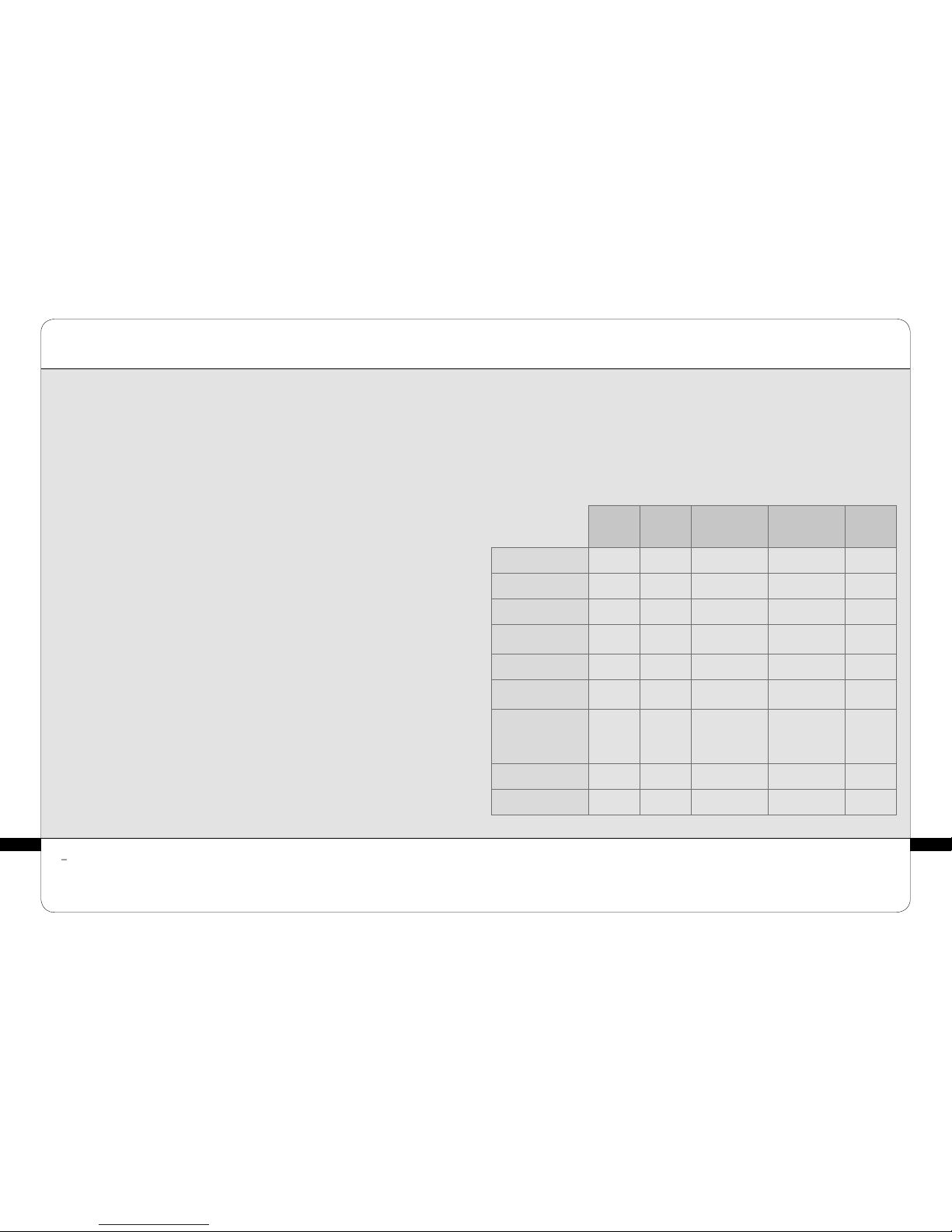
Europe VII-H05VVF3G1,50-C19; Italy I/3/16-H05VVF3G1,50-C19; Switzerland 23G-H05VVF3G1.50-C19; UK
BS13/13-H05VVF3G1,50-C19; Japan 498GJ-VCTF3X2.00-C19; USA, Canada, Mexico N5/15-SJT3X14AWG-C19
(connect to Hospital grade receptacle in hospital environnement).
> IMPORTANT SAFETY INFORMATION
PRECAUTIONS FOR USE
3
PRECAUTIONS FOR USE
3
> PRECAUTIONS FOR USE
> IMPORTANT SAFETY INFORMATION
> WARNING
All safety precautions must be observed whilst using electrical equipment. Please read all
safety notices and precautions prior to use of the equipment.
• Never touch the patient and the device’s
unprotected cables or connectors simultaneously.
• Never use the adapter as a treatment head or
allow it to come into direct contact with the skin.
• Only use treatment heads supplied with your unit
or recommended by LPG.
• Do not use the treatment heads directly on the
skin. Wear the treatment suit provided by LPG
Systems, ENDERMOWEAR.
• LPG Systems will not be liable for any
inappropriate use of the equipment.
• Improper use of the device can cause tissue
damage or pain.
• The operator must be particularly attentive to
the sensations felt by the person undergoing
treatment.
• The operator must ensure that the parameters
(intensity, sequentiality, differential...) are always
adapted to the tissue being treated.
• Do not lean, rest, or sit on the unit.
• When crossing a threshold or step, we
recommend moving the unit carefully by firmly
holding the central arm monitor stand to avoid
the risk of tipping.
• Do not use the USB connection during treatment.
• Do not operate the unit in unsuitable
environmental conditions (see technical
specifications).
• The power plug is used as disconnect device.
The disconnection of the unit is disconnecting
the power plug.
• Please position your device so that the mains
unit is always accessible.
• Do not touch the patient and the hose connectors
simultaneous
• Do not use the treatment heads in contact with
vegetable oils
≥ATTENTION
• Always disconnect the equipment from the
electrical supply outlet after use and before
cleaning and maintenance.
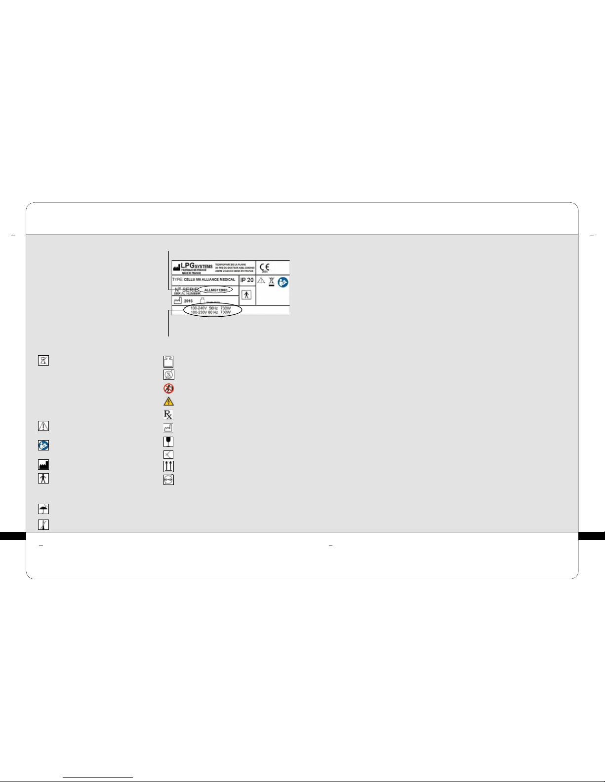
• Check that the supply voltage of the unit
indicated on the data plate complies with the
mains voltage.
• The unit must be connected by the power
cord1 supplied to a grounded outlet in
accordance with current electrical standards.
Electrical adapters must not be used with this
equipment.
• Ensure that the unit is connected to a
system with a differential protection
against DC and AC.
DANGER - TO MINIMISE THE RISK OF ELECTRICAL SHOCK:
• TO MINIMISE THE RISK OF BURNS, FIRE,
ELECTRICAL SHOCK OR INJURY:
• The equipment must not be left unattended
whilst connected to the electrical supply.
• Disconnect the unit from the electrical
supply if it is not going to be used for a
long period.
• Special attention is required whilst using
the equipment with, or in the proximity of
children or disabled persons.
• Never use the unit for purposes other than
those recommended by LPG Systems. Only
use the treatment heads supplied with your
unit or recommended by LPG.
• Never use the equipment if:
The electrical power cord or outlet is
damaged. The equipment does not function
correctly. The equipment is damaged or has
fallen or been dropped. The equipment has
been exposed to excessive humidity.
• Do not move the unit by pulling the electrical
power cord.
• Fully unwind the electrical power cord and
keep it away from warm surfaces.
• Never use the equipment if the ventilation
ports are obstructed. Ensure that the
ventilation ports are kept clear of dust or
other contaminants.
• Do not allow solid debris, liquid or other
foreign bodies to fall or be sucked into the
unit, as these could cause damage.
• Never use the equipment on a dusty, uneven
floor, or in a moist atmosphere.
• Never use the equipment in the presence
of aerosols or oxygen.
• Before disconnecting the unit from the
electrical supply, set all controls to the
‘off’ position and unplug the unit. The
disconnection of the unit is disconnecting
the power outlet.
• It is prohibited to modify this equipment
without prior authorisation from the
manufacturer.
• It is prohibited to use components or spare
parts non recommended by LPG.
• Return the device to LPG Systems Service
Center for examination and repair.
ATTENTION: KEEP THESE INSTRUCTIONS.
Your device should be used on healthy skin. It is important to read and respect the following
precautions and contraindications before using your device.

12 13
This unit contains programs to help the operator obtain the best anticipated results for each case
undergoing treatment. Under no circumstances may these programs be construed as a guarantee of
successful treatment, which varies, depending on the morphology, physiology and eating behavior of
each patient.
≥ATTENTION
> ELECTROMAGNETIC COMPATIBILITY
> CONTRA-INDICATIONS
3
PRECAUTIONS FOR USE
PRECAUTIONS FOR USE
3
• Do not treat open wounds, the eyes,
intra-cavity areas, mucous membranes,
the genitals or breasts.
• This device is not recommended for pregnant
women. In the event of pregnancy, do not
treat the lumbar-abdominal region. Consult
with a doctor with regard to this treatment.
• Do not treat a patient with an infectious
disease, a growing tumour, a phlebitis, a
wound, or an infected area.
• Do not treat a patient with skin cancer, a
visible tumor, or other cancerous lesions.
Consult with a doctor in cases where the
patient has a case history of tumours or is in
remission.
• Do not treat inflamatory areas or scars
without medical advice and LPG technical
training for the affected areas.
• Do not treat people with circulatory problems
without first consulting their doctor and
without training in LPG technology for the
affected areas.
• Do not treat a patient with an unexplained
and persistent pain without medical advice
and without training in LPG technology for
the affected areas.
• Do not treat a patient after an invasive
medical treatment without medical advice or
surgeon who carried out the treatment and
without training in LPG technology for the
affected areas.
• To avoid bruising, exercise caution
when determining a patient’s level of
sensitivity and avoid use on patients taking
anticoagulant drugs.
• Stop treatment immediately if the patient
experiences pain and consult a doctor.
• This device should not be used on
all dermatoses, skin rashes, herpes,
inflammatory or infectious acne or vitiligo.
• Because of the risk of interference, it is
important that the professional ensures
the patient is not equipped with a personal
medical device such as a pacemaker. If this
is the case, the professional should obtain
details about the device in question to ensure
that any interference will not affect the
correct use of the equipment.
• As this list is not exhaustive, always seek out
medical advice in the event of doubt.
• For a more detailed list of indications
and against indications, refer to training
manuals.
• Your CELLU M6® Alliance Medical device requires special care concerning the EMC, it must be
installed and service according to the information provided in this user guide.
• Portable and mobile RF communication devices must not be used near your device, they can
cause undesired operation.
• The use of other treatment heads than those provided by LPG may result in increased
emissions or decreased immunity of the device.
• Your CELLU M6® Alliance Medical device should not be used adjacent to or stacked with other
medical devices.
• Interference may occur near equipment marked with the following symbol:
For more information concerning the electromagnetic compatibility, refer to appedix
« Electromagnetic compatibilty »

14 15
The identification rating plate is located on the underside, at the back of the unit. Identification rating
plates may vary. The approved one is one on your machine.
Proscribe aggressive products such as acetone, trichlorethylene or alcohol at 90°.
≥ ≥
ATTENTION ATTENTION
MAINTENANCE
4
MAINTENANCE
4
> IDENTIFICATION RATING PLATE > CLEANING THE UNIT
This icon indicates that the unit was sold after
August 13, 2006. In conformity with the
2002/96/CE directive, it cannot be thrown away
with standard household waste but must be
disposed of by means of recycling. When your
device reaches the end of its useful life, it
must be brought to an appropriate recycling
center or returned to your dealer. By doing so,
you help the environment by contributing to
the conservation of natural resources and the
protection of human health.
This icon indicates that some specific
warnings or precautions associated with
this device are not on the label.
This symbol means you must consult the
accompanying documents before using
your device.
This symbol indicates the name and address
of the manufacturer.
This symbol means that your device has type
BF applied parts which come into contact
with the patient. These parts are electrically
isolated from all of the device’s other parts.
These applied parts are: the treatment heads.
This symbol means store the device
somewhere protected from inclement
weather.
This symbol indicates temperature limits.
This symbol indicates the weight of the device
This symbol indicates relative humidity limits.
This symbol means « Do not push »
This symbol means « danger: High Voltage »
This symbol means
« use under prescription » (US only).
This symbol indicates the year of the
manufacturing
This symbol indicates fragile, handle with
care
This symbol indicates keep it vertical
This symbol indicates not reverse
This symbol indicates athospheric pressure
limits.
Your unit is identified by a serial number
shown on the rating plate. The rating plate
also shows the permitted supply voltage for
the unit. If you need to contact LPG Systems
because of a technical problem, please
indicate the serial number of your CELLU
M6® Alliance Medical. This serial number
provides information on the year and month
of manufacture of your unit.
The letter indicates the year the device was
manufactured. Z=2009, A=2010, B=2011, etc.
The two digits indicate the production month:
01=January; 02=February; 03=March; etc.
serial
number
voltage,
frenquency
and power
It is recommended that you clean your unit as often as possible, not only for reasons of
hygiene and aesthetics but also because cleaning the unit will help keep it in a good state
of repair and extend its useful life.
Using a vacuum cleaner with a fine nozzle, clean the following sections:
• Interior of the head storage drawer.
• Interior of the head storage tray.
• Interior of the filter access door.
Using a moist sponge, clean the following sections:
• All the external hoods.
• Hoses.
• The electrical power cord.
Using a cloth soaked with a small amount of alcohol-free domestic cleaning product,
clean the following sections:
• Control screen and control panel.
• Interior of the head storage drawer.
• Interior of the head storage tray.
• Interior of the filter access door.
Using an antistatic cloth soaked or wipes, clean:
• The touch screen.
The maintenance of the treatement heads should be performed before the first use, see
chapter «treatment heads».

1716
≥ATTENTION
MAINTENANCE
4
MAINTENANCE
4
FILTER METER
FIG. 6
1. Open the filter access door.
(Fig 1)
2-3. Unscrew and remove the filter
cartridges and replace them with
new ones. (Fig 2 et Fig 3)
4. Remove the filter foam and
replace it with a new one.
(Fig 4 et Fig 5)
Remember to purchase new filter
cartridges from the LPG Systems
Customer Service Department so
you always have a spare
.
FIG. 1 FIG. 2
FIG. 3
5. Once the filter cartridge is
replaced, the filter meter should
be reset by pressing the icon
indicated:
(Fig 6)
> REPLACING THE FILTER CARTRIDGES AND FOAM
FIG. 5
FIG. 4
FIG. 1
FIG. 3
FIG. 2
FIG. 4 FIG. 5
The device must never be used without a filter. If no filter is fitted, the device must be switched off.
Your device contains two filter cartridges and one filter foam.
These components guarantee the efficiency of your unit and prolongs its useful life.
The ‘filter change’ screen indicates
which filter requires changing (Fig. 5).
Ensure that they are changed as
soon as the command screen
displays one of these messages
(Fig 1-2) :
Icon indicating a filter change is
required (Fig. 2).
Access the ‘filter change’ menu as
follows :
Select the ‘maintenance’ menu by
pressing the icon indicated (Fig. 3).
Select the ‘filter’ menu by pressing
the icon indicated (Fig. 4).
Replace the filter cartridges as follows :
> REPLACING THE FILTER CARTRIDGES AND FOAM
FILTER TO CHANGE
PRESS THIS ICON
PRESS THIS ICON
CHANGE THE FILTERS

18 19
> CONNECTING / DISCONNECTING
THE MOTORIZED TREATMENT HEADS
MAINTENANCE
4
MAINTENANCE
4
FIG. 2
FIG. 4 FIG. 5
To connect the heads to the hose, follow the
procedure below.
Position the locking ring in the locked position
(Fig.1)
Position the end of the hose so that the hose key
is lined-up with the key slot of the treatment head
connection (Fig.2)
Push the hose into the treatment head connection
until it cliks into place.
FIG. 3
> CONNECTING / DISCONNECTING THE ADAPTER
ADAPTER CONNECTION MICRO-HEADS AND
MICRO-NOZZLES CONNEXION
To connect or disconnect the hose
adapter, follow the procedures described
on the chapter 4.4 « Connecting /
Disconnecting the motorized treatment
heads ».
The connection is made with a simple
push/pull movement.
HOSE CONNECTION
TREATMENT HEAD
CONNECTION
FIG. 1
LOCKING RING
ORNEMENTAL
RING
LOCKED
POSITION HOSE KEY
KEY
SLOT
To disconnect the heads to the hose, follow the procedure below.
Position the locking ring in the unlocked position (Fig.3)
Pull the locking ring towards the hose (Fig.4)
Carefully remove the hose by pulling it by the white ring (Fig.5)
UNLOCKED
POSITION
Only the micro-heads and the micro-nozzles can be connected to the adapter.
The connexion is made with a simple push/pull movement.
UNLOCKED LOCKED

212020
> INSTRUCTION TO REMOVE USB PROTECTIVE COVER
MAINTENANCE
4 > MAINTENANCE LOG SHEET
Replacement of filter cartridges: To be done when the warning message.
Replacement of sealing flap: To be done when the flaps no longer treat the skin
properly. They should be replaced after every 100 hours of use.
DATE N° OF HOURS OPERATION PERFORMED
MAINTENANCE
4
> REPLACING THE POWER CORD
If the power cord of your device is damaged, please contact LPG Systems Customer Service
for a replacement.
LPG Systems Customer Service: +33(0)4 75 78 69 00
Remove the access cover to the USB port by using
the appropiate tool.

22 23
TECHNICAL SPECIFICATIONS
6
> WHAT IF I’VE A PROBLEM ?
TROUBLESHOOTING
5 > TECHNICAL SPECIFICATIONS
Dimensions LxWxH: .................................................61x70x140 cm
Net weight: ...............................................................80,5 kg
Maximum set depression: . . . . . . . . . . . . . . . . . . . . . . . . . . . . . . . . . . . . . . . . .69 kPa (690 mbar)
Cooling: ...........................by mechanical ventilation incorporated in the pump
Protection index: ............................................................IP 20
Electrical protection class: .......................................................1
Wifi: ...............................................................2,4Ghz b/g/n
Electrical features: ............................................100-240V 50Hz 730W
. . . . . . . . . . . . . . . . . . . . . . . . . . . . . . . . . . . . . . . . . . . . . . . . . . . . . . . . . . . . . 100-230V 60Hz 730W
Operating environmental features:
Ambient temperature: .................................. + 10 à + 30°C for normal use.
Ambient relative humidity: .............................30 à 75% without condensation.
Atmospheric pressure: ............ 800 à 1050 hPa (For use in a normally ventilated room)
Max altitude: ............................................................. 2500m
Environmental characteristics of transport and storage:
Temperature: ..................................................... -20°C to +70°C
Ambient relative humidity: ............................10 to 90% without condensation
Atmospheric pressure : ........... 800 to1050 hPa (For use in a normally ventilated room)
Your device is equipped with patented treatment heads (applied parts type of BF).
The CELLU M6
®
Alliance Medical device is marked as a medical device by virtue
of Annex II of regulation 93/42/EEC (applicable standards IEC 60601-1 Ed3 and related
standards).
If your unit is not working properly, proceed with the following checks before calling
Customer Services:
• Is the unit properly connected to a mains plug?
• Is the mains plug live?
• Is the ON switch lit up?
• Are the filter cartridges clean and correctly placed?
• Are the hoses properly connected?
• Are the treatment heads properly connected ?
• Is the connected treatment head connected corresponds to that shown on the screen?
Once these checks have been carried out and if the malfunction persists, please contact
Customer Services of LPG Systems or the nearest authorized dealer, indicating the model
of your unit and its serial number.
Service Client de LPG Systems :
+33 (0)4 75 78 69 00

24 25
TÊTES DE TRAITEMENT
7
TREATMENT HEADS
7 > INDEX
CELLU M6® Alliance Medical DESCRIPTION OF ALLIANCE 80 HEAD. . . . . . . . . . . . . . . . . . . . . . . . . . . . . . . . . . . . . . . 26
DESCRIPTION OF ALLIANCE 50 HEAD. . . . . . . . . . . . . . . . . . . . . . . . . . . . . . . . . . . . . . . 28
DESCRIPTION OF TR30 HEAD .............................................30
DESCRIPTION OF ERGOLIFT HEAD .........................................31
DESCRIPTION OF MICRO-HEADS AND MICRO-NOZZLES ........................32
MAINTENANCE .........................................................33
TREATMENT HEADS
Registered trademark

26 27
TREATMENT HEADS
7
TREATMENT HEADS
7 > DESCRIPTION OF THE ALLIANCE 80 HEAD
> DESCRIPTION OF THE ALLIANCE 80 HEAD
BRIGHT LEDS
ADJUSTMENT OF ROLLER AND FLAP POSITION
Alliance head 80 has an adjustable stop with 2 positions for adjusting the
distance between the motorized roller and of the damper.
When the cursor is in the horizontal position, the maximum mobility of the
rollers is ensured.
When the cursor is in the vertical position, the minimum mobility of the rollers
is ensured.
START / STOP BUTTON The Alliance 80 head can be used to
the Endermologie body treatment.
PARAMETER SETTING
BUTTONS
EMBELLISHER FLAP
NAVIGATION BUTTONS
ADJUSTEMENT
SLIDER
POSITION
ROLLER AND FLAP
EMBELLISHER FLAP
MOTORIZED FLAP
MOTORIZED ROLLER
MINIMUM SPACING
POSITION
MAXIMAL
SPACING
POSITION
To change the adjustment slider turns it into the holding down to the desired
position, as shown in the photo below:

2928
7
TÊTES DE TRAITEMENT
7 > DESCRIPTION OF ALLIANCE 50 HEAD
> DESCRIPTION OF ALLIANCE 50 HEAD
TÊTES DE TRAITEMENT
The Alliance 50 head can be used to
the therapeutic treatment (fibrosis,
edema, inflammation …).
PARAMETER SETTING
BUTTONS
NAVIGATION BUTTONS
START / STOP BUTTON
EMBELLISHER FLAP
MOTORIZED FLAP
ADJUSTEMENT SLIDER
POSITION ROLLER
AND FLAP
MOTORIZED ROLLER
MOTORIZED FLAP
TREATMENT CHAMBER
ADJUSTMENT OF ROLLER AND FLAP POSITION
Alliance head 80 has an adjustable stop with 2 positions for adjusting the
distance between the motorized roller and of the damper.
When the cursor is in the horizontal position, the maximum mobility of the
rollers is ensured.
When the cursor is in the vertical position, the minimum mobility of the rollers
is ensured.
MINIMUM SPACING
POSITION
MAXIMAL
SPACING
POSITION
To change the adjustment slider turns it into the holding down to the desired
position, as shown in the photo below:

3130 31
TREATMENT HEADS
7
TREATMENT HEADS
7
> DESCRIPTION OF THE ERGOLIFT HEAD
> DESCRIPTION OF ERGOLIFT CHAMBERS
> DESCRIPTION OF TR30 HEAD
Lift 20
Treatment
chamber with
removable flap
Only the LIFT 20 and LIFT 10
can be connected to the Ergolift
head. Thay can be connected
and disconnected by a simple
push-pull action.
Lift 10
Treatment
chamber with
removable flap
SELECTION BUTTON FOR TREATMENT TYPE
POWER INCREASE BUTTON
POWER DECREASE BUTTON
ON / OFF BUTTON
HOSE CONNECTION
ERGOLIFT CHAMBER CONNECTION
They can be connected and
disconnected by a simple
push-pull action.
PARAMETER
SETTING BUTTONS
ROLLER LOCKING MECHANISM
START / STOP BUTTON
SEALING FLAP
MOTORIZED ROLLERS
The Egolift chamber Lift 20 can be used to the treatment of large areas with fine
tissues, and sensible areas. The Ergolift chamber Lift 10 can be used to the treatment
to tight areas, eyes and lip contour, hands and figers.

3332
TREATMENT HEADS
7 > DESCRIPTION OF MICRO-HEADS AND MICRO-NOZZLES
TREATMENT HEADS
7
> MAINTENANCE
For reasons of hygiene, the maintenance of the treatment heads should be performed after
each use, using antiseptic wipes impregnated with a bactericidal and fungicidal solution.
Special attention must be given to the maintenance of the parts that are in contact with the
patient.
THE ALLIANCE 80 HEAD
1. Remove the sealing flaps (2 up flaps and 1 down flap) as showed in the pictures below
(fig 1 à 4).
2. Thoroughly rub for at least one minute with the wipes as describe here below.:
a) Flaps and their housing (fig 5 to 7).
b) The casing on both sides of the rollers (turn the head over, rotate the rollers
manually to clean the entire surface) (fig. 8).
c) The motorized flap (Don’t mobilize the motorized flap) (fig 9 & 10).
d) Le sabot
3. Reattach the sealing flaps
4. Maintain the storage drawer using LPG wipes, then place the head in it.
NOZZLE CONNECTIVE
TR 15 HEAD
MICRO-NOZZLES
MICRO-HEADS
Fig 1 Fig 2 Fig 3 Fig 4
Fig 5 Fig 6 Fig 7 Fig 8
Fig 9 Fig 10

3534
> MAINTENANCE 77 > MAINTENANCE
Don’t mobilize the motorized flap manually.
≥ATTENTION
THE ALLIANCE 50 HEAD
1. Remove the sealing flaps (2 up flaps and 1 down flap) as showed in the pictures below
(fig 1 to 4).
2. Thoroughly rub for at least one minute with the wipes as describe here below.:
a) Flaps and their housing (fig 5 to 7).
b) The casing on both sides of the rollers (turn the head over, rotate the rollers
manually to clean the entire surface) (fig. 8)
c) The motorized flap (Don’t mobilize the motorized flap) (fig 9 & 10).
d) Le sabot
3. Reattach the sealing flaps
4. Maintain the storage drawer using LPG wipes, then place the head in it.
THE TR30 HEAD
1. Remove the sealing flaps as showed in the pictures below (fig 1).
2. Thoroughly rub for at least one minute with the wipes as describe here below:
a) The flaps and their housing (fig 2 & 3).
b) The casing on both sides of the rollers (turn the head over, rotate the rollers
manually to clean the entire surface) (fig. 4)
c) Le sabot
3. Reattach the sealing flaps
4. Maintain the storage drawer using LPG wipes, then place the head in it.
TREATMENT HEADS
TREATMENT HEADS
Fig 1 Fig 2 Fig 3 Fig 4
Fig 5 Fig 6
Fig 7
Fig 8
Fig 9 Fig 10
Fig 1
Fig 2
Fig 3 Fig 4

3736
77
TREATMENT HEADS
TREATMENT HEADS
FIG. 3
FIG. 1
FIG. 2
1. Disconnect the micro-heads or micro-nozzles
from the adapter.
2. For the micro-heads, use the dedicated tool
provided (fig 1 & 2).
3. Thoroughly rub for at least 1 minute the
rollers, seal, treatment chamber, microheads
disassembly tool, and micro-nozzles with LPG
wipes soaked in a bactericide and fungicide
solution (fig. 3).
4. Refit the rollers and check they spin freely.
5. To maintain the micro-heads use cotton
soaked with the same solution.
6. Maintain the storage drawer using LPG wipes,
then place the heads in it.
MICRO-HEADS AND MICRO-NOZZLES
> MAINTENANCE > MAINTENANCE
DESINFECTING THE MICRO-HEADS AND MICRO-NOZZLES
The motorized treatment heads (Alliance 80, Alliance 50 and TR30) need to be used with
an Endermowear suit. Non-motorized treatment heads (micro-nozzles, and micro-heads)
can be used directly on the skin in specific cases.
In these cases, the heads need to be disinfected after each use:
1. Use the maintenance procedure described above.
2. Soak the rollers, micro-heads, disassembly tool, and micro-nozzles in a disinfectant for
12 minutes at 20° C, as recommend on the disinfectant packaging.
3. Carefully rinse the flap and the treatment chamber with sterile or drinking water for at
least 1 minute using a large volume of water (approximately 8 liters). Repeat twice for
a total of 3 rinses.
4. Dry the parts.
5. Pre-clean the storage drawer using LPG wipes, then place the head in it.
Use a disinfectant whose active ingredient is ortho-phthalaldehyde (OPA). Before using the disinfectant, read and follow
the recommendations, contraindications, and warnings associated with this product. Refer to the instructions for using
this solution. All the procedures described in this section must be carried out with the machine turned off and the power
cord unplugged. - Do not use corrosive products such as acetone, trichloroethylene, or rubbing alcohol, nor abrasive
sponges.
≥ATTENTION

3938 39
87 > MAINTENANCE
> ENDERMOWEARTM
LPG EndermowearTM is available in several sizes for men and women and has been specially
designed for body treatments. It is intended for personal use, guarantees hygiene, and its
opaque areas cover the patient’s intimate parts during the treatment. EndermowearTM’s
unique material guarantees excellent adhesion to the skin which facilitates movement of the
treatment head.
The products are delivered in a bag that the customer can personalize by putting their name
on the label. It becomes the customer’s property and can be used for several sessions. For
esthetic reasons and hygiene, it should be washed after each use. Please refer to the washing
instructions indicated on the bag label.
TREATMENT HEADS
ENDERMOWEARTM
ERGOLIFT HEAD AND ERGOLIFT CHAMBERS
FIG. 3
FIG. 1 REMOVAL TOOLS
FIG. 2
ROTATION 90°
ROTATION 90°
FIG. 4
DESINFECTING OF ERGOLIFT CHAMBERS
The use of aggressive products, such as acetone, trichloroethylene, or alcohol at 90°, and abrasive sponges, ultrasound
or UV lamps is strictly prohibited. All cleaned and/or disinfected heads should be placed in the storage drawer to avoid
any confusion. Use a disinfectant whose active ingredient is ortho-phthalaldehyde (OPA). Before using the disinfectant,
read and follow the recommendations, contraindications, and warnings associated with this product. Refer to the
instructions for using this solution. All the procedures described in this section must be carried out with the machine
turned off and the power cord unplugged.
≥ATTENTION
For reasons of hygiene, the maintenance of the treatment heads should be performed after
each use, using antiseptic wipes impregnated with a bactericidal and fungicidal solution.
Special attention must be given to the rub of the parts that are in contact with the patient.
1. Disconnect the chamber from the Ergolift treatment head. (fig. 1)
2. Remove the flap thanks to the dedicated tool. (fig. 2)
3. Thoroughly rub the Ergolift chamber, the flap and the tool for at least one minute
with the wipes as describe here below. (fig. 3)
4. Put the flap back in the Ergolift chamber by following the same steps in the reverse
order (fig. 4)
The Ergolift head is in direct contact with patient’s skin. Under certain specific applications,
it needs to be disinfected after each use:
1. Follow the maintenance procedure described above.
2. Soak the flap and Ergolift chamber in an OPA disinfectant for 12 minutes at 20° C,
as recommended on the disinfectant packaging.
3. Carefully rinse the flap and the Ergolift chamber with sterile or drinking water for at least
1 minute using a large volume of water (approximately 8 liters). Repeat twice for a total of
3 rinses.
4. Dry the Ergolift chamber and flap.
5. Clean the storage drawer with antiseptic wipes, then place the Ergolift chamber and flap
in it.
> MAINTENANCE
Other manuals for CELLU M6 Alliance Medical
1
Table of contents
Other LPG Medical Equipment manuals

LPG
LPG CELLU M6 Alliance Medical User manual

LPG
LPG Cellu M6 User manual

LPG
LPG HUBER 360 EVOLUTION User manual

LPG
LPG Cellu M6 User manual

LPG
LPG Cellu M6 Alliance User manual

LPG
LPG WELLBOX S User manual

LPG
LPG Mobilift M6 Connect User manual

LPG
LPG CELLU M6 Alliance Lab Medical User manual

LPG
LPG Cellu M6 Alliance Technical manual

LPG
LPG HUBER 360 EVOLUTION User manual