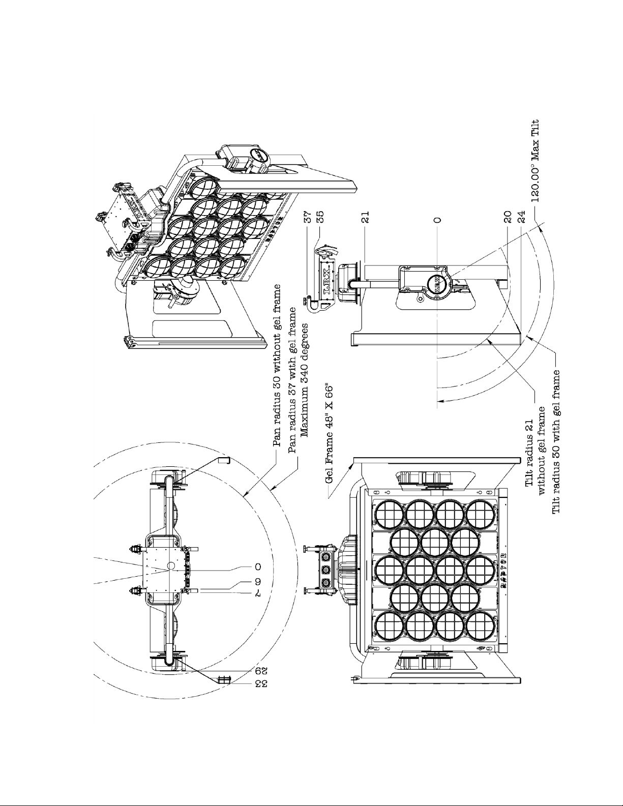
LRX RAPTOR User manual

LRX™ RAPTOR
www.lrx-lighting.com
Check on line for the latest updates at www.lrx-lighting.com
SPECIFICATIONS SUBJECT TO CHANGE WITHOUT NOTICE
1
1

LRX RAPTOR DAILY CHECKLIST
Read and understand LRX Raptor Manual before proceeding with daily checklist and/or
operation of any LRX fixture. Manual available in fixture transport case or online at
www.lrx-lighting.com.
POWER UP CHECKS
TRUSS CONNECTION POINT
CABLES
IF THE FIXTURE FAILS ANY PART OF THIS INSPECTION, REMOVE POWER, LOCK OUT AND REPORT TO YOUR
SUPERVISOR IMMEDIATELY. DO NOT ATTEMPT TO MAKE REPAIRS, ALL REPAIRS TO LRX LIGHTING
FIXTURES ARE TO BE PERFORMED BY AN LRX AUTHORIZED DEALER ONLY.
HEAD STRUCTURAL INSPECTION REFERENCE IMAGES
1.
2.
3.
4.
5.
6.
7.
8.
9.
10.
11.
12.
13.
14.
15.
16.
17.
18.
#
#
#
#GOOD /
FAIL
GOOD /
FAIL
GOOD /
FAIL
GOOD /
FAIL
FIG. 1
FIG. 2
CUSTOMER:
DATE:
LOCATION:
FIXTURE SERIAL #:
INSPECTED BY: SIGNATURE:
19.
20.
21.
22.
23.
24.
25.
Confirm the combined weight of all accessories are within the allowable weight restrictions of the aerial lifting device or supporting structure.
Notes:
Inspect fixture attachment hooks head structure for damage, cracks or loose bolts.and
Inspect ratchet straps. There must be a minimum of two wraps around each ratchet drum.
Ensure the straps capture truss strap clips are correctly placed and latched.and
Ensure hanger keeper bolts are installed completely.
Inspect overall condition of fixture / structure.
Ensure all covers are installed in good condition.and
Inspect all lamps, retaining grills mounting hardware.and
Inspect lamp sockets, contacts wires.and
Inspect gel frame receivers.
Inspect gel frame holders mounting hardware.and
Inspect Socapex cable input connectors and contacts.
Inspect data connectors and contacts.
Inspect condition of U ground plug, wire strain relief.and
Provide safety cables where required for accessories.
Ensure no components have been modified outside of manufactures specifications.
Inspect truss for damage, cracks, dents, distortion.
Inspect truss mounting plates for damage, cracks and distortion.
Inspect all fasteners and hardware for damage and ensure all fasteners are secure.
Inspect truss supporting structure and capacity.
Inspect data cable, connectors and contacts for damage.
Ensure all power and data cables are correctly connected to fixture.
Ensure proper electrical power is supplied.
Ensure all power and data cables have a secure strain relief.
Ensure hanger LED display and keypad operating properly.
Inspect hand controller for damage and proper function.
Test tilt, pan and flood / spot function.
HANGER BOLTS
ATTACHMENT
HOOKS
LIFTING HANDLE
RATCHET
STRAPS
SOCAPEX
CONNECTIONS
GEL
FRAME
KEEPER
PINS
GEL FRAME
HOLDERS
GEL FRAME
BOLTS LAMP
RETAINING
GRILL
GEL FRAME
SAFETY CLIPS GEL FRAME
SAFETY
WIRE
ATTACHMENT
POINTS
00299

LRX™ RAPTOR
www.lrx-lighting.com
Check on line for the latest updates at www.lrx-lighting.com
SPECIFICATIONS SUBJECT TO CHANGE WITHOUT NOTICE
2
2
WARNING
READ EQUIPMENT MANUFACTURES
MANUAL BEFORE USING THIS PRODUCT
SAFETY INSTRUCTIONS
User must be authorized, qualified and certified in jurisdiction of use.
It is the user’s responsibility and obligation to determine and comply with
all applicable laws and regulations.
Do not operate if unit appears damaged.
Always use approved safety cables secured to a point capable of supporting
the total weight of the load.
In case of malfunction disconnect all power supplies, discontinue use, notify
supplier.
Area under fixture must be cordoned off at all times and kept clear of all
personnel.
Prior to operation a daily inspection and log are required.
For handling information see page eleven.
If using a power trolley with this fixture please refer to “LRX Power Trolley”
manual.
THERE ARE NO USER SERVICEABLE PARTS.
IF YOU ARE UNSURE ABOUT ANYTHING SUSPEND USE OF THE PRODUCT.
Questions contact LRX LLC service representative at lrx-lighting.com and go
to contact page.
For the latest version of this manual please visit “lrx-lighting.com”
DANGER
Dangerous voltages are present when power is supplied to the fixture.
This fixture has more than one power supply. Disconnect all power supplies
before installation or removal of the lamps.
Ensure all power supplies are off when connecting or disconnecting any
cabling.
Ensure lamp power supply matches lamp manufactures specification.
Always stand clear of fixture during ignition cycle.
Power must be removed when not in use and when data signal is removed.
Ensure fixture meets all local codes prior to operation.

LRX™ RAPTOR
www.lrx-lighting.com
Check on line for the latest updates at www.lrx-lighting.com
SPECIFICATIONS SUBJECT TO CHANGE WITHOUT NOTICE
3
3
Safety power lockout procedures must be followed.
Safe electrical and working practices must be observed.
WARNING
This fixture has rotating parts with pinch points.
Fixture may move without warning.
No personal within range of motion
Never operate with any covers missing.
WARNING
High energy light output will burn skin and ignite combustible materials. Do
not operate in the proximity of materials that are adversely affected by heat
or light.
Lamp housing becomes very hot when in operation.
Never look directly at the light source
When fixtures are mounted in close proximity to one another, care must be
taken so that output energy from one fixture is not directed at another
fixture or electrical cabling.
FIXTURE ADDRESSING
Fixture addressing is performed at the rear of the fixture hanger assembly.
The fixture can be programmed to operate in DMX mode or FIXTURE mode
(for use with the hand controller). Because each LRX fixture requires sixteen
DMX channels for operation, FIXTURE mode is merely a convenient way of
skipping DMX channels in 16 channel increments, beginning with DMX
channel #001. Additionally, fixture mode provides power to a connected hand
controller, which is also designed to work in 16 channel increments.
DMX Connector pin out: (also see important note below)
Pin 1 = ground
Pin 2 = Data negative
Pin 3 = Data positive
Pin 4 = 12VDC negative
Pin 5 = 12 VDC positive

LRX™ RAPTOR
www.lrx-lighting.com
Check on line for the latest updates at www.lrx-lighting.com
SPECIFICATIONS SUBJECT TO CHANGE WITHOUT NOTICE
4
4
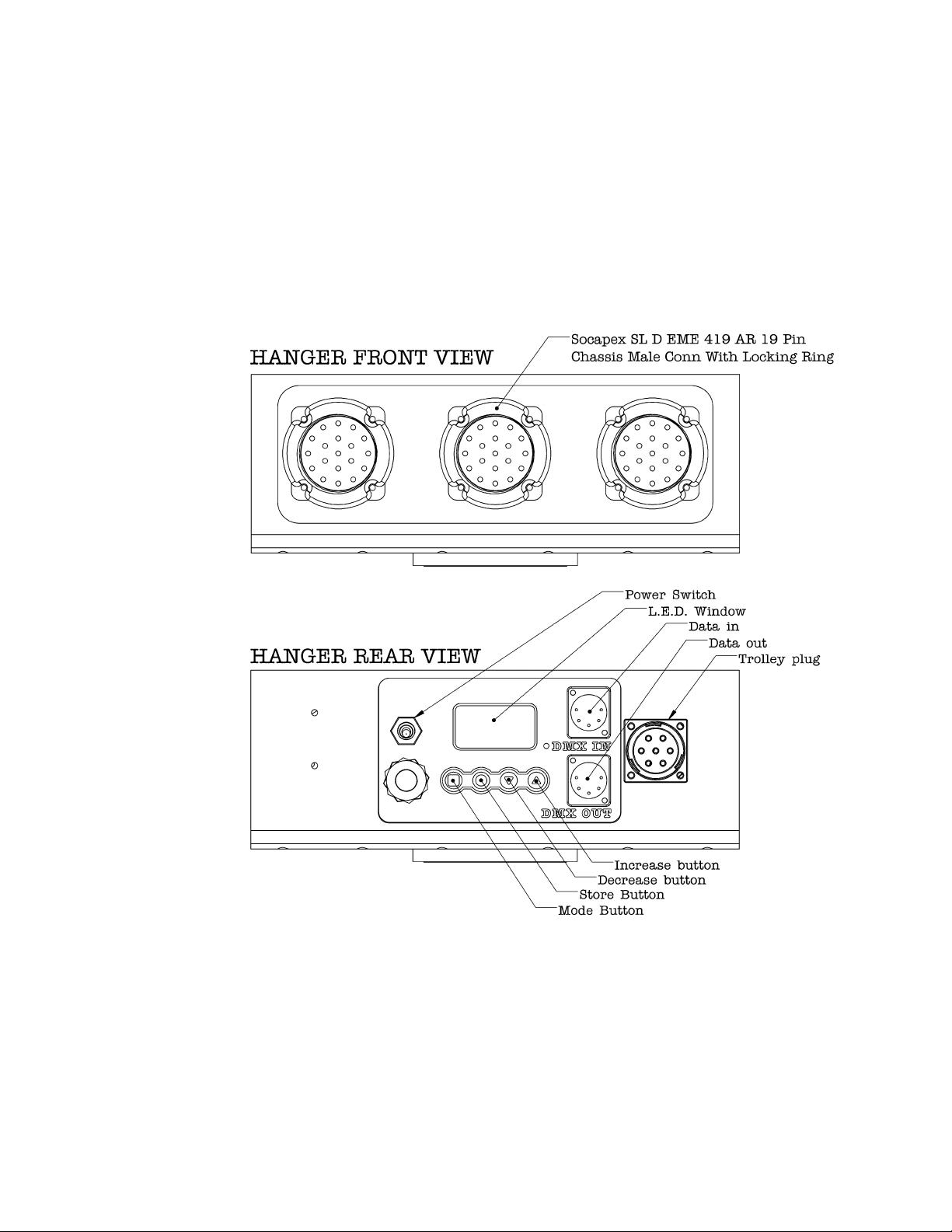
When the LRX fixture is in FIXTURE mode, pins 4 & 5 on the DMX IN
connector become energized to 12VDC to supply power to the hand controller.
No power is supplied to pins 4 & 5 when in DMX mode. Ensure that fixture is
in the correct mode prior to connecting DMX lines. Always connect the hand
controller to the fixture with the power off. Damage could result if attempting
to connect the hand controller to the LRX fixture while the power is on.
The mode (square icon) on the left is used to toggle between DMX mode and
FIXTURE mode. FIXTURE mode is designated by a capital ‘F’ in the left-most
digit, with the remaining two digits indicating the fixture number. E.g.
F01=fixture#1, etc. DMX mode is shown as a three digit number from 001 to
512. Once the mode is selected the fixture number or DMX address can be
increased or decreased using the up/down arrows on right side of the switch
assembly. When the correct FIXTURE/address has been selected, the store
(round icon) button second from the left is pressed and held (until the display
stops flashing) to store that address.
It is important to note that the LRX
fixture will not begin responding to a newly selected FIXTURE/DMX address
until it has been stored by pressing and holding the store (round icon) button.
If the display is flashing, this is a warning that the displayed FIXTURE/DMX
address does not match the address that fixture is currently responding to.
Saving the displayed address tells the fixture to begin listening and responding
to the new address. If the address is not stored within five seconds it will
return to the previous set
The LRX fixture always writes the last saved address and mode to non-volatile
memory, such that in the event of a power interruption, the fixture will power
up with the mode and address it was using before the power interrupt.
Pressing and holding the mode button will provide access to the hour meter.
Once in hour meter mode press the up icon to display bulb hours, indicated as
a scrolling number. It will show as a blank digit followed by three digits then a
decimal place and two more digits (i.e. _120.59). The bulb hours can be reset
by pressing and holding the store button until the meter zeros, about five
seconds.
To display fixture hours, press the down icon. Fixture hours will be displayed
as a scrolling number with an “F” prefix. This can’t be reset by the user.

LRX™ RAPTOR
www.lrx-lighting.com
Check on line for the latest updates at www.lrx-lighting.com
SPECIFICATIONS SUBJECT TO CHANGE WITHOUT NOTICE
5
5

LRX™ RAPTOR
www.lrx-lighting.com
Check on line for the latest updates at www.lrx-lighting.com
SPECIFICATIONS SUBJECT TO CHANGE WITHOUT NOTICE
6
6
DMX CHANNEL ALLOCATION
When using the LRX with a lighting console or other device that offers
discrete control over the DMX channels, they are used by the fixture as follows:
Where N= base channel of fixture. [LRX DMX address shown on display]:
N + (0-9) = motor control (depends on MODE)
N+10 = GEL fan ON/OFF (OFF<127<=ON)
N+11 = lamp control (unimplemented)
N+12 = motor control MODE: N+12<127 = BUMP MODE
N+12>=127 = FADER MODE
N+13 = reserved (future use)
N+14 = reserved (future use)
N+15 = reserved (future use)
If (MODE = BUMP): (n+12<128)
(N+0 > 127) = pan left
(N+1 > 127) = pan right
(N+2 > 127) = tilt up
(N+3 > 127) = tilt down
(N+4 > 127) = spot
(N+5 > 127) = flood
(N+6 > 127) = trolley left
(N+7 > 127) = trolley right
(N + 8, 9) = reserved (future use)
If (MODE=FADER): (n+12>=128)
(N+0 < 64) = pan left
(N+0 > 127) = pan right
(N+1 < 64) = tilt up
(N+1 > 127) = tilt down
(N+2 < 64) = spot
(N+2 > 127) = flood
(N+3 < 64) = trolley left
(N+3 > 127) = trolley right
(N+4 thru 9) = reserved (future use); each motor above is stopped
when the fader is in the middle of its range (DMX value 64-127)

LRX™ RAPTOR
www.lrx-lighting.com
Check on line for the latest updates at www.lrx-lighting.com
SPECIFICATIONS SUBJECT TO CHANGE WITHOUT NOTICE
7
7
HAND CONTROLLER
The hand controller will allow fixture selection,(up to 32 fixtures), control of
tilt - up/down, pan - left/right and flood/spot functions and will also shut off
individual gel cooling fans or all gel cooling fans connected to that controller.
All switches act as momentary type. When the “Individual Gel Fan Stop” switch
is held the gel fan for the fixture indicated on the display stops. When the “All
Gel Fans Stop” switch is held all gel fans connected to that hand controller will
stop.

LRX™ RAPTOR
www.lrx-lighting.com
Check on line for the latest updates at www.lrx-lighting.com
SPECIFICATIONS SUBJECT TO CHANGE WITHOUT NOTICE
8
8
FIXTURE SPECIFCATIONS
Electrical
Control power:
Volts: 120 AC –non dimmed feed line.
Hertz: 50 - 60
Amps: 2.0
Connector: U- Ground plug/Edison plug.
Lamps:
500 & 1,000 Watt par 64 type lamps with a GX16D base
Volts –120/240 VAC
Hertz –50/60
Input Connector for lamps: Socapex SL61-19 Contacts/Model:
419AR
Quantity: Three (six lamps per connector/one lamp per circuit)
Data: DMX protocol
Data connector:
XLR type, five pin & five wire
Pin 1 = ground
Pin 2 = Data negative
Pin 3 = Data positive
Pin 4 = 12VDC negative
Pin 5 = 12 VDC positive
Physical:
Tilt: Range one hundred degrees - vertical (Zero degrees) to
negative one hundred and twenty degrees
Pan: 340 degrees
Weight: 170 pounds approximate
Gel frames: 48” X 65”
Fixture mounting hooks have been designed to mate with truss
chords not greater than two inches (50.8mm) in diameter

LRX™ RAPTOR
www.lrx-lighting.com
Check on line for the latest updates at www.lrx-lighting.com
SPECIFICATIONS SUBJECT TO CHANGE WITHOUT NOTICE
9
9

LRX™ RAPTOR
www.lrx-lighting.com
Check on line for the latest updates at www.lrx-lighting.com
SPECIFICATIONS SUBJECT TO CHANGE WITHOUT NOTICE
10
10
GEL FRAMES
To install gel frame holders, loosen four thumb screws located on the front
of the fixture housing.
Slide the keyhole slots located on the gel frame holder over the loosened
thumb screws and lower into place.
Tighten thumb screws and install the four safety clips provided.
The outside gel slot must be used first as this will hold the two gel frame
holders together. No gel material is to be used on the side of the filter frame
that has been slotted. These slots will mate with bend returns on the outer
most slot of the filter frame holder. See illustration.
Install the supplied gel frame safety pins in the top two corners. See
illustration.
SAFETY CABLES REQUIRED

LRX™ RAPTOR
www.lrx-lighting.com
Check on line for the latest updates at www.lrx-lighting.com
SPECIFICATIONS SUBJECT TO CHANGE WITHOUT NOTICE
11
11
HANDLING OF FIXTURE
Heavy lift, minimum two persons, the weight is approximately 170 pounds.
Hanging of the fixture creates a number of potential pinch points.
Use fixture lifting handles provided as well as the yoke tubes.
If there are any concerns regarding handling please contact your
supervisor.
Ensure hanger bolts are installed immediately after hanging, before the
ratchet straps are tensioned.
Ratchet straps must have a minimum of one and a half wraps around the
ratchet drum at all times.
Removal of shipping case covers require two persons to lift. Always use
lifting handles provided to avoid potential pinch points.
Fixture lifting points
Fixture approximately
170 pounds

LRX™ RAPTOR
www.lrx-lighting.com
Check on line for the latest updates at www.lrx-lighting.com
SPECIFICATIONS SUBJECT TO CHANGE WITHOUT NOTICE
12
12
Notice, to enable the fixture to fit into the shipping case:
Tilt fixture so that panel is vertical.
Pan fixture so that it is pointed straight ahead.
Install onto shipping frame, tighten hanger bolts and ratchet straps; ensure
there is a minimum of 1.5 wraps on the ratchet drum.
Secure gel frame holders using the Velcro straps provided in the shipping
trays.
Place hand controller into Pelican case and place in tray.
Hang DMX cables on shipping stand.
Always store equipment in a dry location.
Ensure 1.5 wraps
on ratchet drum
Hanger Bolt

LRX™ RAPTOR
www.lrx-lighting.com
Check on line for the latest updates at www.lrx-lighting.com
SPECIFICATIONS SUBJECT TO CHANGE WITHOUT NOTICE
13
13
LAMP INSTALLATION
A number of hazards exist during lamp installation please refer to
safety warnings on page two.
Follow lamp manufactures instructions regarding use and handling of their
product.
This fixture has more than one power supply. Disconnect all power supplies
before installation or removal of the lamps.
Allow lamps to cool before removing.
Loosen the two screws that hold the lamp retaining ring, then rotate ring to
remove.
Prior to installing the lamp, check lamp contacts and wire ends for signs of
arcing or over-heating. If lamp contacts or wiring appear damaged remove
from service.
Ensure power supply matches lamp type, voltage and wattage.

LRX™ RAPTOR
www.lrx-lighting.com
Check on line for the latest updates at www.lrx-lighting.com
SPECIFICATIONS SUBJECT TO CHANGE WITHOUT NOTICE
14
14
INSTALLATION OF FIXTURES ON TRUSS, I-BEAM
OR TELESCOPIC TYPE MAN LIFTS
THIS FIXTURE MUST BE MOUNTED ON A LEVEL TRUSS.
Installation structure must be designed and approved to safely carry all
anticipated loads.
It is the user’s responsibility and obligation to determine and comply with
all applicable laws and regulations.
The installation and operation of this unit must be carried out by
authorized and qualified personnel.
Hanger bolts in hanger assembly must be installed. Both ratchet straps
must be clipped onto their respective anchor point.
Ratchet straps require minimum of 1.5 wraps on the ratchet to ensure they
remain tight.
Always use approved safety cables secured to a point capable of supporting
the total weight of the load.
All power and data cables
must
have a strain relief attached.
When fixtures are mounted in close proximity to each other, care must be
taken so that output energy from one fixture is not directed at another
fixture or electrical cabling.
Power trolleys must have positive mechanical stops on beams.
If cable rollers are required refer to “LRX Cable Roller” manual.
If LRX truss is to be installed, ensure that load is centered and evenly
applied to basket. Maximum capacity for LRX truss is 500 pounds evenly
distributed.
Never use damaged or compromised trusses or equipment.
Follow all lift manufactures guide-lines for load/wind capacities and de-
rating as required. Refer to the aerial equipment operator manuals & special
supplement for “Authorized and Trained Set Lighting Technicians and
Studio Grips”.

LRX™ RAPTOR
www.lrx-lighting.com
Check on line for the latest updates at www.lrx-lighting.com
SPECIFICATIONS SUBJECT TO CHANGE WITHOUT NOTICE
15
15
`
Load must be centered front
to back as well as side to side
Using two truss plates (1/2” X 3”)
per side, a minimum of two
structural members must be
captured. Fasten using ½” X 4”
bolts with washers, lock washers
and nuts –four places

LRX™ RAPTOR
www.lrx-lighting.com
Check on line for the latest updates at www.lrx-lighting.com
SPECIFICATIONS SUBJECT TO CHANGE WITHOUT NOTICE
16
16
TROUBLE SHOOTING GUIDE
NO DISPLAY AT REAR OF HANGER ASSEMBLY
Ensure 120vac power to fixture is live and on a non-dimmed line.
Remove DMX connectors and inspect contact pins for damage and signs of
corrosion
Inspect 120 volt U ground supply wire for cuts or mechanical damage
Inspect U ground plug contacts.
Power switch is on (up position)
FIXTURE DOESN’T RESPOND TO ANY FUNCTIONS
REQUESTED FROM HAND CONTROLLER
Establish power is correct and display is functioning properly, see above.
Test with another hand controller if available. If still unresponsive proceed
to next step.
Remove DMX connectors and inspect contact pins for damage and no signs
of corrosion. Note all five wires and pins are required to operate hand
controller.
Check hanger display for proper addressing and mode. For use with hand
controller the fixture display must show the “F” prefix; not the three digit
DMX channel and the display must not be flashing.
It is important to note that the LRX fixture will not begin responding to a
newly selected FIXTURE/DMX address until it has been stored by pressing
and holding the store (round icon) button. If the display is flashing, this is
a warning that the displayed FIXTURE/DMX address does not match the
address that the fixture is currently responding to.
Plug hand controller directly into fixture, at this point the hand controller
should light up and DMX light on the fixture should also light up. At this
point if the unit is not operational test with another hand controller.
Ensure the address at the fixture matches the address on the hand
controller.
If still not operational, place fixture into DMX mode and test with an
alternative DMX source.
Call for service

LRX™ RAPTOR
www.lrx-lighting.com
Check on line for the latest updates at www.lrx-lighting.com
SPECIFICATIONS SUBJECT TO CHANGE WITHOUT NOTICE
17
17
TILT, PAN OR FOCUS MOTOR
NOT OPERATING CORRECTLY.
Head moves freely without control:
This may indicate the fixture has received impact and the drive gear has
been damaged or drive may have become disengaged.
Head not moving on one axis but other axis is fine
Test with another hand controller if available. If still unresponsive proceed
to next step.
This may indicate the fixture has received impact and the drive gear has
been damaged or drive may have become disengaged.
Actuate drive function and listen for motor operation. The tilt and pan drive
assemblies use a slip clutch inline between the motor and drive gear as a
protective measure, this clutch will slip and make a clicking sound once
each revolution when driven by the motor, if the clutch has exceeded it
preset limits.
If any of these conditions exist, suspend use of the product and call for
service.
There are no user serviceable parts.
LAMPS NOT WORKING
Check Soca extension cables and fixture panel mount connector pins
Ensure correct lamp input power is available at head cable.
Check lamps, socket contacts and wiring.
TROLLEY DOESN’T RESPOND
Dangerous voltage present at socket.
Test with LRX hardwired trolley hand controller. If it now works problem
with fixture, hand controller, lighting console.

LRX RAPTOR DAILY CHECKLIST
Read and understand LRX Raptor Manual before proceeding with daily checklist and/or
operation of any LRX fixture. Manual available in fixture transport case or online at
www.lrx-lighting.com.
POWER UP CHECKS
TRUSS CONNECTION POINT
CABLES
IF THE FIXTURE FAILS ANY PART OF THIS INSPECTION, REMOVE POWER, LOCK OUT AND REPORT TO YOUR
SUPERVISOR IMMEDIATELY. DO NOT ATTEMPT TO MAKE REPAIRS, ALL REPAIRS TO LRX LIGHTING
FIXTURES ARE TO BE PERFORMED BY AN LRX AUTHORIZED DEALER ONLY.
HEAD STRUCTURAL INSPECTION REFERENCE IMAGES
1.
2.
3.
4.
5.
6.
7.
8.
9.
10.
11.
12.
13.
14.
15.
16.
17.
18.
#
#
#
#GOOD /
FAIL
GOOD /
FAIL
GOOD /
FAIL
GOOD /
FAIL
FIG. 1
FIG. 2
CUSTOMER:
DATE:
LOCATION:
FIXTURE SERIAL #:
INSPECTED BY: SIGNATURE:
19.
20.
21.
22.
23.
24.
25.
Confirm the combined weight of all accessories are within the allowable weight restrictions of the aerial lifting device or supporting structure.
Notes:
Inspect fixture attachment hooks head structure for damage, cracks or loose bolts.and
Inspect ratchet straps. There must be a minimum of two wraps around each ratchet drum.
Ensure the straps capture truss strap clips are correctly placed and latched.and
Ensure hanger keeper bolts are installed completely.
Inspect overall condition of fixture / structure.
Ensure all covers are installed in good condition.and
Inspect all lamps, retaining grills mounting hardware.and
Inspect lamp sockets, contacts wires.and
Inspect gel frame receivers.
Inspect gel frame holders mounting hardware.and
Inspect Socapex cable input connectors and contacts.
Inspect data connectors and contacts.
Inspect condition of U ground plug, wire strain relief.and
Provide safety cables where required for accessories.
Ensure no components have been modified outside of manufactures specifications.
Inspect truss for damage, cracks, dents, distortion.
Inspect truss mounting plates for damage, cracks and distortion.
Inspect all fasteners and hardware for damage and ensure all fasteners are secure.
Inspect truss supporting structure and capacity.
Inspect data cable, connectors and contacts for damage.
Ensure all power and data cables are correctly connected to fixture.
Ensure proper electrical power is supplied.
Ensure all power and data cables have a secure strain relief.
Ensure hanger LED display and keypad operating properly.
Inspect hand controller for damage and proper function.
Test tilt, pan and flood / spot function.
HANGER BOLTS
ATTACHMENT
HOOKS
LIFTING HANDLE
RATCHET
STRAPS
SOCAPEX
CONNECTIONS
GEL
FRAME
KEEPER
PINS
GEL FRAME
HOLDERS
GEL FRAME
BOLTS LAMP
RETAINING
GRILL
GEL FRAME
SAFETY CLIPS GEL FRAME
SAFETY
WIRE
ATTACHMENT
POINTS
00299
Table of contents
Other LRX Lighting Equipment manuals
Popular Lighting Equipment manuals by other brands

Qlightec
Qlightec STND Series quick start guide

Anslut
Anslut 003-600 operating instructions

PIU39
PIU39 PLUSLITE ARKIWASH-PL021 User instructions

Il Fanale
Il Fanale BORGO 244.40 Instruction for correct Installation and Use

Evenlite
Evenlite IPX Quick start quide

Osram
Osram Traxon e:cue Allegro Media Tube Lite Mounting guide

Clevertronics
Clevertronics L10 LJELED-40 Series ASSEMBLY, INSTALLATION & MAINTENANCE INSTRUCTIONS

Barco
Barco OLite 510 supplementary guide

MicMol
MicMol Aqua mini quick start guide

iGear
iGear Camo iG-1021 quick start guide

Laserworld
Laserworld BeamBar 10R-638 manual

Vision & Control
Vision & Control DL60x60-IR850/UDC/-a Instructions for use