LRX SCORPION User manual

LRX™ SCORPION
SPECIFICATIONS SUBJECT TO CHANGE WITHOUT NOTICE
FILE: S- DRIVE – DAVID – LRX-650 – TEXT – Scorpoin-650 se up manual.doc –
Word documen and PDF - LAST REVISED – Augus 10, 2008
1
1

LRX™ SCORPION
SPECIFICATIONS SUBJECT TO CHANGE WITHOUT NOTICE
FILE: S- DRIVE – DAVID – LRX-650 – TEXT – Scorpoin-650 se up manual.doc –
Word documen and PDF - LAST REVISED – Augus 10, 2008
2
2
IMPORTANT:
1. The ins alla ion, opera ion and servicing of his fix ure o be carried ou by only
au horized and qualified personnel.
2. Ensure his uni mee s all local codes prior o opera ion.
3. Do no opera e if uni appears damaged.
4. Repor damage immedia ely.
5. This uni has more han one power supply. Disconnec all power supplies before
servicing or bulb ins alla ion/removal o avoid elec ric shock.
6. Do no connec or disconnec under load.
7. Ensure power supplies are off when making fix ure, power supply and da a
connec ions.
8. Lamp housing and ligh energy ou pu very ho when in opera ion. Do no opera e
in proximi y of subs ances or ma erials ha are flammable or adversely affec ed
by hea or ligh .
9. In case of malfunc ion disconnec power supplies, discon inue use, no ify supplier.
10. Spare fuses for con rol func ions are loca ed inside he hanger assembly. Replace
fuses only wi h he exac ype and amperage ra ing.
11. No user serviceable par s
12. Unsure abou any hing or ques ions, con ac represen a ive before use.
13. When fix ures are moun ed in close proximi y o one ano her, care mus be aken
so ha ou pu energy from one fix ure is no direc ed a ano her fix ure.
14. For he la es version of his manual please visi “lrx-ligh ing.com”
FIXTURE SPECIFCATIONS:
Bulbs: This uni will accep 650 Wa DWE ype bulbs
Elec rical ra ings:
Con rol power - Vol s – 120 AC – non dimmed feed line.
Her z – 50 - 60
Amps – 8.0
Connec or - U- Ground plug/Edison plug.
Lamps – Vol s – 120 VAC
Her z – 50 - 60
Amps/Circui – 20 Maximum
Head Inpu Connec or for lamps:
Socapex SL61 Connec or – 19 Con ac s --- Model – 419AR
Quan i y: Two
Da a - DMX pro ocol – Connec or – Five pin and five wire

LRX™ SCORPION
SPECIFICATIONS SUBJECT TO CHANGE WITHOUT NOTICE
FILE: S- DRIVE – DAVID – LRX-650 – TEXT – Scorpoin-650 se up manual.doc –
Word documen and PDF - LAST REVISED – Augus 10, 2008
3
3
Physical:
1. Til – Range one hundred degrees - ver ical (Zero degrees) o nega ive one
hundred degrees
2. Pan - 340 degrees (non con inuous)
3. Weigh - 135 pounds
4. Gel frames 46” X 46”
BULB INSTALLATION
1. Disconnec all power supplies before ins alling or removing lamp.
2. Allow bulbs o cool before removing.
3. Loosen he wo screws ha hold he bulb re aining ring, hen ro a e ring o
remove.
4. Follow bulb manufac ures ins ruc ions regarding use and handling of heir
produc .
5. Prior o ins alling he lamp, check bulb con ac s and wire ends for signs of
arcing or over hea ing. If bulb con ac s or wiring appear damaged con ac
fix ure supplier prior o use.
6. The power wire a achmen screws should be igh ened as required by he
manufac urer.
7. Ensure power supply ma ches lamp ype vol age and wa age.
8. Tes all lamps.
DMX CHANNEL ALLOCATION
When using he LRX wi h a ligh ing console or o her device ha offers discre e
con rol over he DMX channels, hey are used by he fix ure as follows:
Where N= [LRX DMX address shown on display]:
N + (0-9) = mo or con rol (depends on MODE)
N+10 = GEL fan ON/OFF (OFF<127<=ON)
N+11 = lamp con rol (unimplemen ed)
N+12 = mo or con rol MODE: N+12<127 = BUMP MODE
N+12>=127 = FADER MODE
N+13 = reserved (fu ure use)
N+14 = reserved (fu ure use)
N+15 = reserved (fu ure use)

LRX™ SCORPION
SPECIFICATIONS SUBJECT TO CHANGE WITHOUT NOTICE
FILE: S- DRIVE – DAVID – LRX-650 – TEXT – Scorpoin-650 se up manual.doc –
Word documen and PDF - LAST REVISED – Augus 10, 2008
4
4
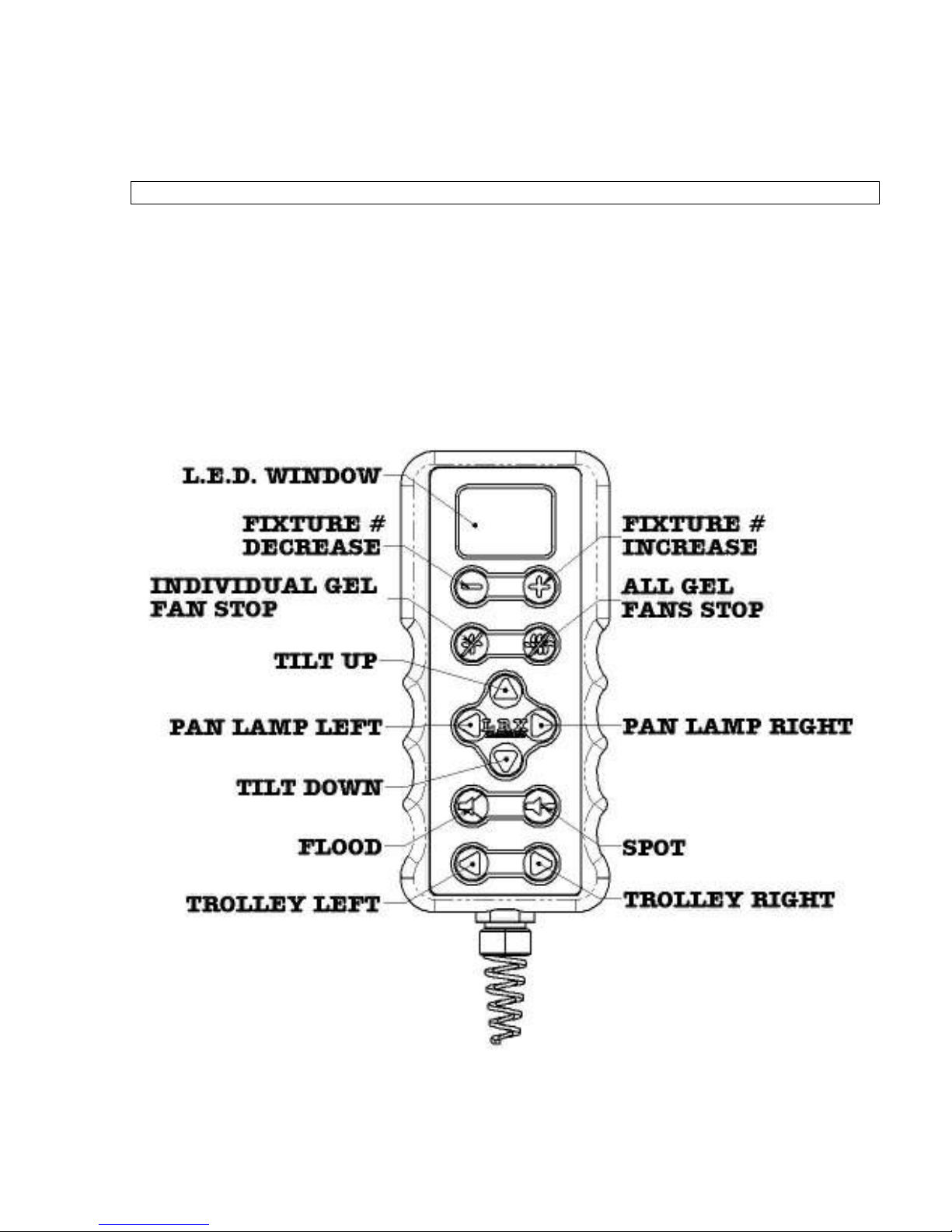
If (MODE = BUMP): (n+13<127)
(N+0 > 127) = pan lef
(N+1 > 127) = pan righ
(N+2 > 127) = il up
(N+3 > 127) = il down
(N+4 > 127) = spo
(N+5 > 127) = flood
(N+6 hru 9) = reserved (fu ure use)
If (MODE=FADER): (n+13>=127)
(N+0 < 64) = pan lef
(N+0 > 127) = pan righ
(N+1 < 64) = il up
(N+1 > 127) = il down
(N+2 < 64) = spo
(N+2 > 127) = flood
(N+3 hru 9) = reserved (fu ure use); Each mo or above is s opped when he
fader is in he middle of i s range (DMX value 64-127).
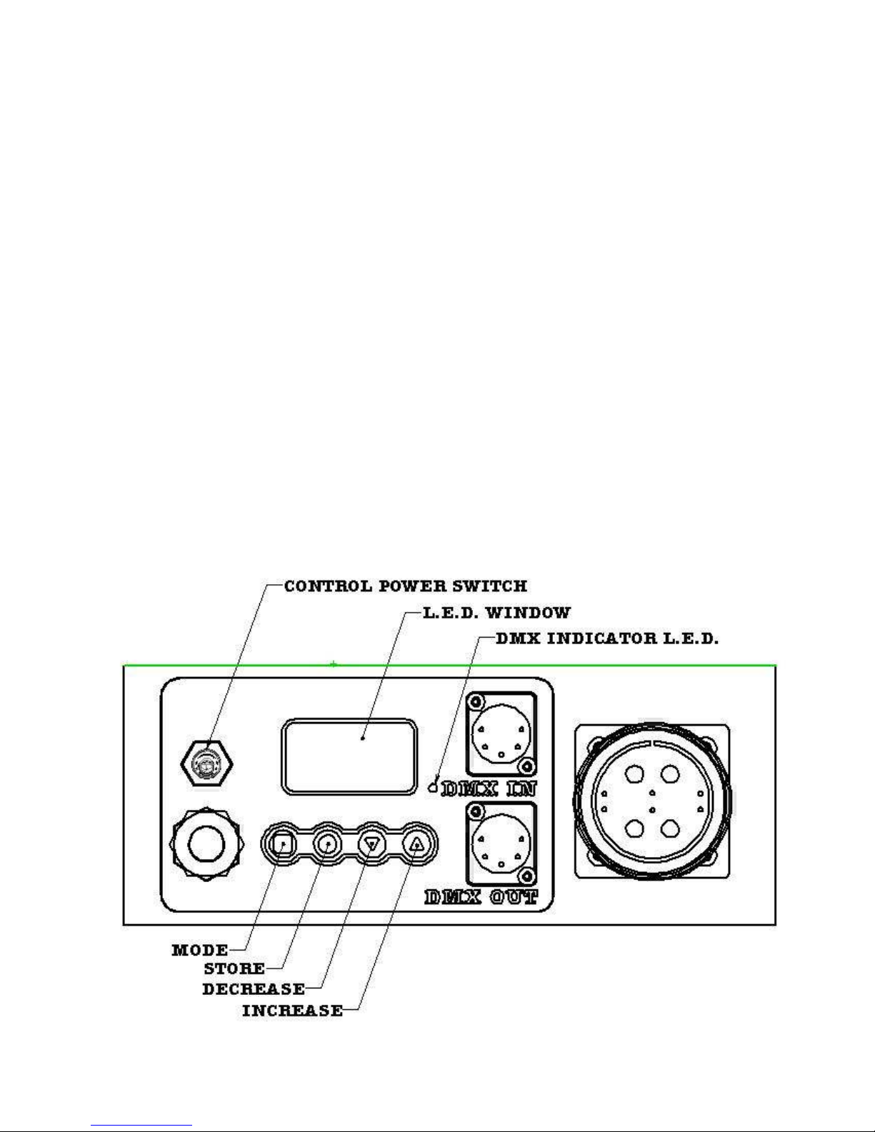
FIXTURE ADDRESSING
Lamp addressing is performed a he rear of he hanger assembly. The fix ure can be
programmed o opera e in DMX mode or FIXTURE mode (for use wi h he hand
con roller). Because each LRX fix ure requires six een DMX channels for opera ion,
FIXTURE mode is merely a convenien way of skipping DMX channels in 16 channel
incremen s, beginning wi h DMX channel #001. Addi ionally, fix ure mode provides
power o a connec ed hand con roller, which is also designed o work in 16 channel
incremen s.
The mode (square icon) on he lef is used o oggle be ween DMX mode and FIXTURE
mode. FIXTURE mode is designa ed by a capi al ‘F’ in he lef -mos digi , wi h he
remaining wo digi s indica ing he fix ure number. E.g. F01=fix ure#1, e c. DMX
mode is shown as a hree digi number from 001 o 512. Once he mode is selec ed he
fix ure number or DMX address can be increased or decreased using he up/down
arrows on righ side of he swi ch assembly. When he correc FIXTURE/address has
been selec ed, he s ore (round icon) bu on second from he lef is pressed and held
(un il he display s ops flashing) o s ore ha address.
I is impor an o no e ha
he LRX fix ure will no begin responding o a newly selec ed FIXTURE/DMX address
un il i has been s ored by pressing and holding he s ore (round icon) bu on.
If he
display is flashing, his is a warning ha he displayed FIXTURE/DMX address does
no ma ch he address ha fix ure is curren ly responding o. Saving he displayed
address ells he fix ure o begin lis ening and responding o he new address.

LRX™ SCORPION
SPECIFICATIONS SUBJECT TO CHANGE WITHOUT NOTICE
FILE: S- DRIVE – DAVID – LRX-650 – TEXT – Scorpoin-650 se up manual.doc –
Word documen and PDF - LAST REVISED – Augus 10, 2008
5
5
The LRX fix ure always wri es he las saved address and mode o non-vola ile
memory, such ha in he even of a power in errup ion, he fix ure will power up
in he mode and address i was using before he power in errup .
IMPORTANT: When he LRX fix ure is in FIXTURE mode, pins 4 & 5 on he DMX IN
connec or become energized o 12VDC o supply power o he hand con roller. No power
is supplied o pins 4 & 5 when in DMX mode. Ensure ha fix ure is in he correc
mode prior o connec ing DMX lines. Always connec he hand con roller o he fix ure
wi h he power off. Damage could resul if a emp ing o connec he hand con roller
o he LRX while he power is on.
Pressing and holding he mode bu on will provide access o he hour me er. Once in
hour me er mode press he up icon o display bulb hours, indica ed as a scrolling
number. I will show as a blank digi followed by hree digi s hen a decimal place and
wo more digi s (i.e. _120.59). The bulb hours can be rese by pressing and holding he
s ore bu on un il he me er zeros, abou five seconds.
To display fix ure hours, press he down icon. Fix ure hours will be displayed as a
scrolling number wi h an “F” prefix. This can no be rese by he user.

LRX™ SCORPION
SPECIFICATIONS SUBJECT TO CHANGE WITHOUT NOTICE
FILE: S- DRIVE – DAVID – LRX-650 – TEXT – Scorpoin-650 se up manual.doc –
Word documen and PDF - LAST REVISED – Augus 10, 2008
6
6
HAND CONTROLLER
The hand con roller is designed o opera e a maximum of hir y wo fix ures
connec ed o a single con roller; he con roller will provide con rol of he fix ure
selec ion, il (up & down), pan (lef & righ ) , and rolley move lef & righ (when
connec ed o he LRX beam rolley).
Please no e ha he flood/spo func ions and he individual gel cooling fans or all gel
cooling fans swi ches are for use wi h he LRX singles.
All swi ches ac as momen ary ype.

LRX™ SCORPION
SPECIFICATIONS SUBJECT TO CHANGE WITHOUT NOTICE
FILE: S- DRIVE – DAVID – LRX-650 – TEXT – Scorpoin-650 se up manual.doc –
Word documen and PDF - LAST REVISED – Augus 10, 2008
7
7
GEL FRAMES
1. To ins all gel frame holders, loosen four humb screws loca ed on he fron of
he fix ure housing.
2. Slide he keyhole slo s loca ed on he gel frame holder over he loosened humb
screws and lower in o place.
3. Tigh en humb screws and ins all he four safe y clips provided.
4. The ou side gel slo mus be used firs as his will hold he wo gel frame
holders oge her. No gel ma erial is o be used on he side of he fil er frame
ha has been slo ed. These slo s will ma e wi h bend re urns on he ou er mos
slo of he fil er frame holder. See illus ra ion.
5. Ins all he supplied gel frame safe y pins in he op wo corners. See
illus ra ion.

LRX™ SCORPION
SPECIFICATIONS SUBJECT TO CHANGE WITHOUT NOTICE
FILE: S- DRIVE – DAVID – LRX-650 – TEXT – Scorpoin-650 se up manual.doc –
Word documen and PDF - LAST REVISED – Augus 10, 2008
8
8
MOUNTING THE LIGHT IN THE SHIPPING CASE
IMPORTANT: before re-ins alling he fix ure in o he shipping case
1. Til fix ure up un il i reaches i s upper limi swi ch.
1. Pan fix ure so ha i is poin ed s raigh ahead.
2. Ins all and igh en T-bol s and ra che s raps
3. Secure gel frame holders using he Velcro s raps provided in here shipping
rays.
4. Hang gel frames a he of rear shipping s and.
5. Place hand con roller Pelican case and place in ray.
6. Hang DMX cables on shipping s and.
7. Always s ore shipping cases in a dry loca ion.

LRX™ SCORPION
SPECIFICATIONS SUBJECT TO CHANGE WITHOUT NOTICE
FILE: S- DRIVE – DAVID – LRX-650 – TEXT – Scorpoin-650 se up manual.doc –
Word documen and PDF - LAST REVISED – Augus 10, 2008
9
9

LRX™ SCORPION
SPECIFICATIONS SUBJECT TO CHANGE WITHOUT NOTICE
FILE: S- DRIVE – DAVID – LRX-650 – TEXT – Scorpoin-650 se up manual.doc –
Word documen and PDF - LAST REVISED – Augus 10, 2008
10
10
LIFTING THE LIGHT
1. Lif ing wi h chain mo or or o her mechanical means (for ins alla ion only) can
be done using he safe y chain holes direc ly below he main moun ing hooks.
2. Lif ing by hand; Use lif ing handles provided as well as he yoke ubes.
3.
If here are any concerns please con ac your heal h and
safe y represen a ive.
4.
PLEASE NOTE: he fix ure is approxima ely 135 pounds
.
INSTALLATION OF FIXTURES ON TRUSS AND TELESCOPIC TYPE MAN LIFTS
1. This fix ure is in ended o be moun ed on a level russ wi h a ubing diame er
no larger han wo inches and ha he russ is moun ed o a s ruc ure capable
of suppor ing he load being applied.
2. Tee bol s in hanger assembly mus be ins alled and bo h ra che s raps clipped
on o heir locking bol s hen igh ened around he rear cord of he russ. See
pic ure.
3. Safe y wires are required for each fix ure.
4. All feed cables mus have a s rain relief.
5. When fix ures are moun ed in close proximi y o one ano her, care mus be
aken so ha ou pu energy from one fix ure is no direc ed a ano her fix ure.
6. Cable rollers when used on a elescopic lif should only be ins alled on fully
re rac ed boom.
7. LRX russ is o be ins all so ha load is cen ered and evenly applied o baske ,
see illus ra ions. Maximum capaci y for LRX russ is 500 pounds evenly
dis ribu ed.
8. Follow all lif manufac ures guide lines for load/wind capaci ies and de-ra ing
as required. See he JLG & Genie (or o hers) opera or manuals & special
supplemen for Au horized and Trained Se Ligh ing Technicians and S udio
Grips. These guides will be made available wi h his manual and is also
available for our office 1-818-669-3334 / 1-416 287 3107 or on-line a
“lrx-ligh ing.com”

LRX™ SCORPION
SPECIFICATIONS SUBJECT TO CHANGE WITHOUT NOTICE
FILE: S- DRIVE – DAVID – LRX-650 – TEXT – Scorpoin-650 se up manual.doc –
Word documen and PDF - LAST REVISED – Augus 10, 2008
11
11

LRX™ SCORPION
SPECIFICATIONS SUBJECT TO CHANGE WITHOUT NOTICE
FILE: S- DRIVE – DAVID – LRX-650 – TEXT – Scorpoin-650 se up manual.doc –
Word documen and PDF - LAST REVISED – Augus 10, 2008
12
12
PRE-DELIVERY INSPECTION
1. Warning labels in place and in good order.
2. Check socke con ac s for signs of overhea ing or arcing.
5. All hardware in place and igh ened.
6. U-ground plug and cable a hanger assembly in good condi ion.
7. Power up uni and es con rol func ions.
8. Func ion es hanger swi ch assembly, and LED display.
9. Plug in hand con roller and es il , pan, and rolley ou pu .
10. Hanger hooks, T-bol s and ra che s raps in good condi ion.
11. Inpu connec ors secure and in good condi ion.
12. Check yoke for signs of damage.
13. Drive assemblies should be lubed wi h ligh oil every hree mon hs.
14. Visual inspec ion of all wiring should be performed every hree mon hs or
sooner as required
15. Each case should include : 1 - Fix ure
2 - Gel frames
1 - 120 foo DMX cable
1 – 10 foo DMX cable
1 – Hand con roller
TROUBLE SHOOTING GUIDE
FUSES:
1. All fuses are loca ed in he hanger assembly. Ensure all power supplies are
disconnec ed prior o removing any covers. Three fuses are loca ed on he rear
hanger pla e and one 12VDC circui breaker is loca ed near he ransformer.
Spare fuses are provided in he plas ic con ainer on op of he ransformer. If
a fuse is removed from con ainer, please make service depar men aware, so
ha he fuses aken can be replaced.
NO DISPLAY AT REAR OF HANGER ASSEMBLY:
1. Ensure 120vac power o fix ure ( non dimmed line)
2. Power swi ch is on
3. Check fuse # 1 (2 amp)
4. Check power across C7(12vdc)
5. Check power across fuse 4 (12VDC circui breaker).
6. Check ribbon cable from main board o display board.
FIXTURE DOESN’T RESPOND TO ANY FUNCTIONS REQUESTED FROM HAND
CONTROLLER OR OTHER DMX INPUT:
7. Es ablish power is correc and display is func ioning properly, see above.
8. Check hanger display for proper addressing and mode.
9. Tes fix ure wi h he hand con roller supplied; se fix ure o fix ure
mode, he address will have an “F” as a prefix – E.g.-
F01
. When he

LRX™ SCORPION
SPECIFICATIONS SUBJECT TO CHANGE WITHOUT NOTICE
FILE: S- DRIVE – DAVID – LRX-650 – TEXT – Scorpoin-650 se up manual.doc –
Word documen and PDF - LAST REVISED – Augus 10, 2008
13
13
correc FIXTURE/address has been selec ed, he s ore (round icon) bu on
second from he lef on he hanger is pressed and held (un il he display
s ops flashing) o s ore ha address.
I is impor an o no e ha he LRX
fix ure will no begin responding o a newly selec ed FIXTURE/DMX
address un il i has been s ored by pressing and holding he s ore (round
icon) bu on.
If he display is flashing, his is a warning ha he
displayed FIXTURE/DMX address does no ma ch he address ha he
fix ure is curren ly responding o.
10. Ensure he address a he fix ure ma ches he address on he hand
con roller.
11. When he LRX hand con roller is plugged in o he “DMX IN” recep acle a
he rear of he hanger he hand con roller will power up and he DMX
ligh on he hanger will ligh up. If his doesn’ happen ry ano her hand
con roller if available.
12. If he 2
nd
hand con roller does no ligh up, me er across pins #4 & #5 of
he “DMX IN” recep acle a he hanger, i should measure 12VDC. If no
vol age is presen check poly fuse, ( his is loca ed ei her on he main
board or on he fuse block depending on he version). If he fuse checks
ou OK i is possible ha here is a defec ive relay on he main board and
he main PCB should be replaced.
TILT, PAN OR FOCUS MOTOR NOT OPERATING IN ONE OR BOTH DIRECTION OR HAS
LIMITED TRAVEL; BUT OTHERS OPERATE AS NORMAL.
1. Tes wi h ano her hand con roller if available. If s ill unresponsive proceed o
nex s ep.
2. If he problem is wi h a il or pan drive, ac ua e non responsive func ion and
lis en for mo or drive noise. The il and pan drive assemblies use a slip clu ch
inline be ween he mo or and drive gear as a pro ec ive measure, his clu ch
will slip and make a clicking sound once each revolu ion when driven by he
mo or if he clu ch has exceeded i prese limi s. If he clu ch is slipping
inspec he mo or drive assembly; gears, gear lash, bearings e c. The il & pan
mo or drive assemblies can be disengaged from he driven brass gear by
loosening he moun ing bol s and hen re es ed. If mo or drives normal when
disengaged check he brass driven gear for damage o he ee h or o her
mechanical binding wi hin he assembly and repair as required. If he problem
is wi h he flood/spo or rolley func ions proceed o nex s ep.
3. I here is no response a he mo or, remove he hanger cover and check main
PCB mo or ou pu s. 12VDC should be measured across any wo ma ing ou pu s
when a corresponding func ion is selec ed and hen reverse polari y when he
opposi e func ion is selec ed. (See wiring diagram or see below). If any of hese
ou pu s fail o supply he ou pu as required, check he ou pu s individually.
This can be achieved by connec ing one es lead o he sys em nega ive, ( his
is easily found a he nega ive side of he large blue capaci or, blue wire #16),
and hen es suspec ou pu s one by one. Ac ua e he corresponding func ion

LRX™ SCORPION
SPECIFICATIONS SUBJECT TO CHANGE WITHOUT NOTICE
FILE: S- DRIVE – DAVID – LRX-650 – TEXT – Scorpoin-650 se up manual.doc –
Word documen and PDF - LAST REVISED – Augus 10, 2008
14
14
on hand con roller in one direc ion hen he o her direc ion. One of hese wo
direc ions should provide a posi ive 12VDC ou pu , repea es for he ma ing
ou pu . If here is no ou pu he PCB board should be replaced.
A. Pan mo or ou pu labeled M1 - & M1+ a main board
B. Til mo or ou pu labeled M2 - & M2+ a main board
C. Focus mo or ou pu labeled M3 - & M3+ a main board
D. Trolley relay ou pu labeled M4 - & M4+ a main board.
4. If above checks ou good, check rela ed wiring & limi swi ches from PCB o
mo or.
• IF Pan; check for 12VDC across he common side of he wo pan limi swi ches
and hen a he normally closed side of he swi ches when he corresponding
func ion on he hand con roller is selec ed. Nex check a he mo or erminals.
If 12VDC is found a he mo or, replace mo or and es .
• IF Til ; check for 12VDC across he common side of he wo il limi swi ches
and hen a he normally open side of he swi ches when he corresponding
func ion on he hand con roller is selec ed. Nex check a he mo or erminals.
If 12VDC is found a he mo or, replace mo or and es .
• If Focus is no opera ing; check for 12VDC a he mo or, if 12VDC is found a
he mo or, undo fas ener a rod end of he ac ua or and es , if s ill no
working replace linear ac ua or, if ac ua or is opera ing as normal check for
binding of lamp socke carriage and associa ed linkages, repair as required.
TROLLEY DOESN’T TRAVEL OR ONLY TRAVELS IN ONE DIRECTION; ALL OTHER
FUNCTIONS OPERATE AS NORMAL.
1. Tes wi h ano her hand con roller if available. If s ill unresponsive proceed o
nex s ep.
2. Disengage rolley plug from he rear of he hanger assembly and ins all
hardwire rolley hand con roller from rolley shipping case. Power rolley hand
con roller wi h 120VAC , non dimmed line. Tes , if rolley opera es as normal
proceed o nex s ep. If rolley is s ill inopera ive check for mechanical
in erference on I-beam flange or o her signs of mechanical binding. If no hing
is found remove rolley from I-beam, loosen four mo or moun ing bol s on he
rolley side pla es and lif mo or o remove ension on he drive bel s, and now
re es . If he is no response a he drive mo or when es ed replace rolley. If
rolley opera es as normal wi h he rolley hand con roller proceed o nex s ep.
3. Disengage rolley plug from rear of he hanger assembly. Using a mul i-me er
es ou pu a pin’s #A & B, his should measure 120VAC. If i doesn’ check
fuse # 3 in he hanger assembly. If blown replace wi h exac ype/size and
re es . If above es s good check for con inui y be ween pins# D & F when
rolley func ion is selec ed on he LRX hand con roller, check bo h direc ions,
i should show con inui y for one of he wo direc ions. Repea his es for
pins # E & F. (E & F should show con inui y for one direc ion and D & F should
show con inui y for he o her direc ion, see wiring diagram).
4. If above doesn’ check ou remove hanger assembly cover and check he ou pu
of M4 - & M4+ a he main PCB. Check hese ou pu s individually. This can be

LRX™ SCORPION
SPECIFICATIONS SUBJECT TO CHANGE WITHOUT NOTICE
FILE: S- DRIVE – DAVID – LRX-650 – TEXT – Scorpoin-650 se up manual.doc –
Word documen and PDF - LAST REVISED – Augus 10, 2008
15
15
achieved by connec ing one es lead o he sys em nega ive, ( his is easily
found a he nega ive side of he large blue capaci or, blue wire #16), and hen
es suspec ou pu s one by one. Ac ua e he corresponding func ion on hand
con roller in one direc ion hen he o her direc ion. One of hese wo direc ions
should provide a posi ive 12VDC ou pu , repea es for he ma ing ou pu . If
here is no ou pu he PCB board should be replaced. If his es s OK proceed o
he nex s ep.
5. Check rolley circui board loca ed in he hanger assembly. Measure vol age a
relay coil when func ion is selec ed, (12VDC). If he coils are receiving 12VDC
replace his board and re es .

LRX™ SCORPION
SPECIFICATIONS SUBJECT TO CHANGE WITHOUT NOTICE
FILE: S- DRIVE – DAVID – LRX-650 – TEXT – Scorpoin-650 se up manual.doc –
Word documen and PDF - LAST REVISED – Augus 10, 2008
16
16
Other manuals for SCORPION
1
Table of contents
Other LRX Lighting Equipment manuals