LSIS SV110IP5A-4NE User manual

Safety Instructions
i
Thank you for purchasing LS Variable Frequency Drives!
SAFETY INSTRUCTIONS
To prevent injury and property damage, follow these instructions during the
installation and operation of the inverter.
Incorrect operation due to ignoring these instructions may cause harm or damage.
The following symbols are used throughout the manual to highlight important
information.
■The meaning of each symbol in this manual and on your equipment is as
follows.
This is the safety alert symbol.
Read and follow instructions carefully to avoid a dangerous situation.
This symbol alerts the user to the presence of “dangerous voltage” inside the
product that might cause bodily harm or electric shock.
■This manual should be placed in a location where it can be accessed by users.
■This manual should be given to the person who actually uses the inverter and is
responsible for its maintenance.
DANGER
WARNING
CAUTION
This symbol indicates the possibility of
death or serious injury.
This symbol indicates the possibility of
damage to the inverter or other components.
This symbol indicates death or serious injury can
occur if you do not follow instructions.

Safety Instructions
ii
WARNING
Do not remove the cover while power is applied or the unit is in operation.
Otherwise, electric shock could occur.
Do not operate the inverter with the front cover removed.
Otherwise, electric shock can occur due to the exposed terminals and bus bars.
Do not remove the cover except for periodic inspections or wiring, even if
the input power is not applied.
Otherwise, electric shock can occur due to accessing capacitor banks.
Wiring and periodic inspections should be performed at least 10 minutes
after disconnecting the input power and after checking the DC link
voltage is discharged with a meter (below 30VDC).
Otherwise, electric shock could occur.
Operate the switches with dry hands.
Otherwise, electric shock could occur.
Do not use the cable when its insulating tube is damaged.
Otherwise, electric shock could occur.
Do not subject the cables to scratches, excessive stress, heavy loads or
pinching.
Otherwise, electric shock could occur.
CAUTION
Install the inverter on a non-flammable surface. Do not place flammable
materials nearby.
Otherwise, fire could occur.
Disconnect the input power if the inverter has been damaged.
Otherwise, it could result in a secondary accident and fire.
Do not touch the inverter after shutting down or disconnecting it. It will
remain hot for a couple of minutes.
Otherwise, bodily injuries such as skin-burn or damage could occur.
Do not apply power to a damaged inverter or to an inverter with parts
missing even if the installation is complete.
Otherwise, electric shock could occur.
Do not allow lint, paper, wood chips, dust, metallic chips or other foreign
material into the drive.
Otherwise, fire or accident could occur.

Safety Instructions
iii
Equipment is intended for installation in closed electrical operating areas
only
On User’s Manual it shall be made clear that maintenance adjustments
should be made by qualified personnel.
OPERATING PRECAUTIONS
(1) Handling and installation
The iP5A series inverter can be heavy. Lift according to the weight of the product.
Use a hoist or crane to move and install the iP5A series inverter if necessary. Failure
to do so may result in personal injury or damage to the inverter.
Do not stack the inverter boxes higher than the number recommended.
Install the inverter according to instructions specified in this manual.
Do not open the cover during delivery.
Do not place heavy items on the inverter.
Check that the inverter mounting orientation is correct.
Do not drop the inverter, or subject it to hard impact.
Verify the ground impedance 100ohm or less for 230 V Class inverters and 10ohm or
less for 460V class inverters.
Take protective measures against ESD (Electrostatic Discharge) before touching the
pcb boards during inspection, installation or repair.
The inverter is designed for use under the following environmental conditions :
Environment
Ambient temp.
- 10 ~ 50 ℃(14℉~ 122℉)
Decrease 2% of rated current for every 1℃
increase in above 40℃.
Relative humidity
90% Relative Humidity or less (non-condensing)
Storage temp.
- 20 ~ 65 ℃(-4℉~ 149℉)
Location
Protected from corrosive gas, combustible gas, oil
mist or dust (Pollution degree 2 environment)
Altitude, Vibration
Max. 1,000m (3,300ft) above sea level,
Max. 5.9m/sec2(0.6G) or less
Atmospheric pressure
70 ~ 106 kPa (20.67 in Hg ~ 31.3 in Hg)
(2) Wiring
Do not connect power factor correction capacitors, surge suppressors, or RFI filter to
the output of the inverter.
The connection orientation of the motor output cables U, V, W will affect the direction
of rotation of the motor. Verify correct wiring before starting inverter.
Incorrect terminal wiring could result in inverter and/or equipment damage.
Reversing the polarity (+/-) of the terminals could damage the inverter.
Only authorized personnel familiar with LS inverter should perform wiring and

Safety Instructions
iv
inspections.
Always install the inverter before wiring. Otherwise, electric shock or bodily injury can
occur.
Wire insulation recommended for main power circuits.(Refer to Appendix A)
(3) Trial run
Check all parameters during operation. Parameter values might require adjustment
depending on the application.
Always apply voltage within the permissible range of each terminal as indicated in
this manual. Otherwise, inverter damage may result.
Current hunting can be occurred in the low speed territory during testing. It occurs
where the capacity is above 110kW with no-load and the axis is not connected. The
currnet hunting have a gap according to the motor characteristic. It will be
disappeared when the load is connected and it is not the indication of abnormal
condition. If the hunting is occurred seriously, please stop the testing and operates
with the load.
(4) Operation precautions
When the Auto restart function is selected, the inverter will restart after a fault has
occurred.
The Stop key on the keypad can only be used to stop the inverter when keypad
control is enabled. Install a separate emergency stop switch if necessary.
If a fault reset is made with the run command and /or reference signal present, a
sudden start will occur. Check that the run command and /or reference signal is
turned off in advance of resetting any faults. Otherwise an accident could occur.
Do not modify the inverter.
Depending on the motor specifications and user ETH overload settings, the motor
may not be protected by electronic thermal function of inverter.
The operation of the inverter is intended to be controlled by either keypad command
or control input signals. Do not use a magnetic contactor or any other device that
routinely disconnects the inverter and reconnects the inverter to the input supply
power for the purpose of starting and stopping the motor.
A noise filter may be installed to reduce the effect of electromagnetic interference.
Otherwise nearby electronic equipment may be affected.
In cases with input voltage unbalances, install an AC input reactor.
Power Factor capacitors and generators may become overheated and damaged due
to harmonics created by the inverter.
Use an insulation-rectified motor or take measures to suppress the micro surge
voltage when driving 460V class motor with inverter. A micro surge voltage
attributable to wiring constant is generated at motor terminals, and may deteriorate
insulation and damage motor.
Before operating unit and prior to user programming, reset user parameters to default
settings.

Safety Instructions
v
The Inverter can be set to operate a motor at high-speeds. Verify the speed
capability of motor and machinery prior to operating inverter.
Holding torque is not produced when using the DC-Brake function. Install separate
equipment when holding torque is required.
(5) Fault prevention precautions
If required, provide a safety backup such as an emergency mechanical brake to
prevent any hazardous conditions if the inverter fails during operation.
(6) Maintenance, inspection and parts replacement
Do not megger (hi-pot or insulation resistance) test the power or control circuit of the
inverter.
Refer to ‘Chapter 6 Troubleshooting and Maintenance’and parts replacement details.
(7) Disposal
Handle the inverter as an industrial waste when disposing of it.
(8) General instructions
Many of the diagrams and drawings in this instruction manual show the inverter without a
cover. Prior to operating the unit, be sure to restore covers and circuit protection according to
specifications.
(9) Protective requirements
The accessible connections and parts listed below are of protective class 0, it means that the
protection of these circuits relies only upon basic insulation and becomes hazardous in the
event of a failure of the basic insulation. Therefore, devices connected to these circuits must
provide electrical-shock protection as if the device was connected to supply mains voltage. In
addition, during installation these parts must be considered, in relation with electrical-shock,
as supply mains voltage circuits.
This applies to the following circuits :
STARTING CONTACT FUNCTION SELECT
M1,M2,M3, FX [M7], RX [M8], JOG [M6], BX [M5], RST [M4], CM, 24
ANALOG FREQUENCY SETTING
V+, V-, I, A0, B0, 5G (~30kW), CM(37kW~)
EXTERNAL MOTOR THERMAL DETECTION
NT (~30kW), ET (37kw ~), 5G
BUILT-IN RS485 TERMINAL
C+, C-, CM
ANALOG OUTPUT
S0, S1, 5G
CONTACT
3A, 3C, 3B, "A1~4, C1~4"
CONSOLE PORT
FAN CIRCUITS

vi
Table of Contents
CHAPTER 1 - BASIC INFORMATION.............................................................. 1-1
1.1 INSPECTION.........................................................................................................................................1-1
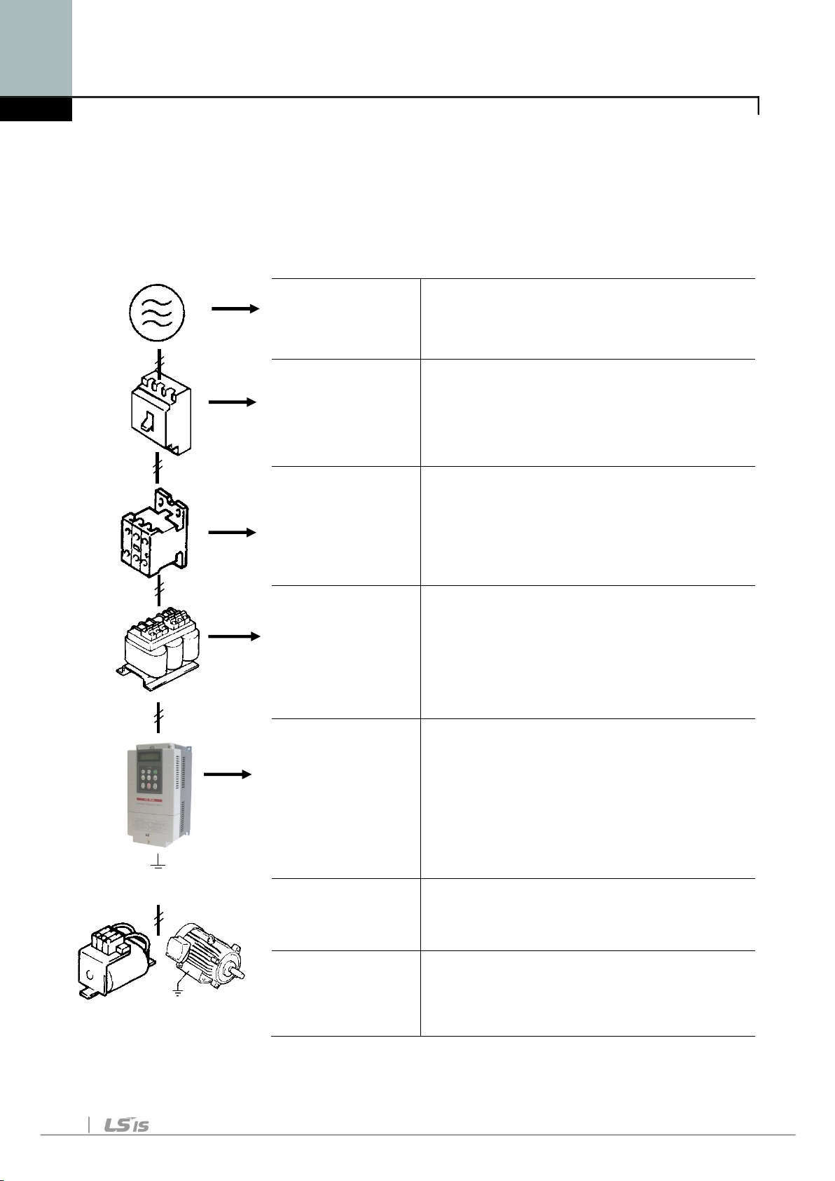
1.2 BASIC CONFIGURATION......................................................................................................................1-2
CHAPTER 2 - SPECIFICATION........................................................................ 2-1
2.1 200~230V CLASS (0.75~30KW/1~40HP)..........................................................................................2-1
2.2 380~480V CLASS (0.75~30KW/1~40HP).........................................................................................2-1
2.3 380 ~480VCLASS (37~90KW/50~125HP)....................................................................................... 2-2
2.4 380 ~480VCLASS (110~450KW/150~700HP).................................................................................2-2
2.5 DIMENSIONS........................................................................................................................................ 2-5
CHAPTER 3 - INSTALLATION ......................................................................... 3-1
3.1 INSTALLATION PRECAUTIONS ........................................................................................................... 3-1
3.2 WIRING ............................................................................................................................................... 3-4
CHAPTER 4 - OPERATION .............................................................................. 4-1
4.1 PROGRAMMING KEYPADS .................................................................................................................4-1
4.2 OPERATING EXAMPLE .......................................................................................................................4-8
4.3 VARIOUS FUNCTION SETTING AND DESCRIPTION ..........................................................................4-13
4.4 OPERATION EXAMPLE ..................................................................................................................... 4-19
CHAPTER 5 - PARAMETER LIST.................................................................... 5-1
5.1 PARAMETER GROUPS ......................................................................................................................... 5-1
5.2 PARAMETER LIST................................................................................................................................5-2
CHAPTER 6 -TROUBLESHOOTING AND MAINTENANCE........................... 6-1
6.1 FAULT DISPLAY.................................................................................................................................. 6-1
6.2 TROUBLESHOOTING...........................................................................................................................6-7
6.3 HOW TO CHECK POWER COMPONENTS ........................................................................................... 6-8
6.4 MAINTENANCE..................................................................................................................................6-10
CHAPTER 7 - OPTIONS.................................................................................... 7-1
CHAPTER 8 - RS485 COMMUNICATION ........................................................ 8-1
8.1 INTRODUCTION...................................................................................................................................8-1
8.2 SPECIFICATION................................................................................................................................... 8-2
8.3 OPERATION......................................................................................................................................... 8-3
8.4 COMMUNICATION PROTOCOL (RS485)............................................................................................. 8-4
8.5 PARAMETER CODE LIST ..................................................................................................................... 8-8
8.6 TROUBLESHOOTING.........................................................................................................................8-13
8.7 ASCII CODE LIST............................................................................................................................. 8-15
CHAPTER 9 - APPLYING DRIVES TO SINGLE-PHASE INPUT
APPLICATION 9-1
9.1 INTRODUCTION...............................................................................................................................9-1
9.2 POWER(HP), INPUT CURRENT AND OUTPUT CURRENT ................................................................9-2
9.3 INPUT FREQUENCY AND VOLTAGE TOLERANCE ...........................................................................9-2
9.4 WIRING AND PERIPHERAL DEVICE.................................................................................................9-2

Table Of Contents
vii
9.5 CONSIDERATIONS WHEN USING A THREE-PHASE DRIVE WITH SINGLE-PHASE INPUT ............. 9-4
APPENDIX A- UL MARKING.....................................................................................I
APPENDIX B- PERIPHERAL DEVICES................................................................VII
APPENDIX C- RELATED PARAMETERS..............................................................IX
EMI / RFI POWER LINE FILTERS ........................................................XI


Chapter 1 –Basic Information
1-1
CHAPTER 1 - BASIC INFORMATION
1.1 Inspection
- Remove the inverter from its packing and inspect its exterior for shipping damage.
If damage is apparent notify the shipping agent and your LSIS sales
representative.
- Remove the cover and inspect the inverter for any apparent damage or foreign
objects. Ensure that all mounting hardware and terminal connection hardware is
properly seated, securely fastened, and undamaged.
- Check the nameplate on the iP5A inverter. Verify that the inverter unit is the
correct horsepower and input voltage for the application.
- Inverter control is applied for AC asynchronous (Induction Motor) Synchronous
motor is excluded.
1.1.1 Inverter model number
The numbering system of the inverter is as shown below.
SV 055 iP5A –2 NE
Motor rating
N : No Keypad
O : UL Open Type
E : UL Enclosed Type 1
L : Built-in DC Choke
055
5.5kW
900
90kW
Series Name
Input Voltage
iP5A
2
200 - 230V
4
380 - 480V
* UL Open type : UL Open type product must be mounted on the panel in a house.
* UL Enclosed type 1 : UL Enclosed type1 product can be mounted without the panel
in a house.
1.1.2 Installation
To operate the inverter reliably, install the inverter in a proper place with the
correct direction and with the proper clearances.
1.1.3 Wiring
Connect the power supply, motor and operation signals (control signals) to the
terminal block. Note that incorrect connection may damage the inverter and
peripheral devices.
Read and understand this manual before installing, operating or servicing this
inverter. The inverter must be installed according to this manual.
The following conventions are used to indicate safety messages in this manual
Failure to heed these messages could result in serious or possibly even fatal
injury or damage to the products or to related equipment and systems.

Chapter 1 –Basic Information
1-2
1.2 Basic configuration
The following devices are required to operate the inverter. Proper peripheral
devices must be selected and correct connections made to ensure proper
operation. An incorrectly applied or installed inverter can result in system
malfunction or reduction in product life as well as component damage. You must
read and understand this manual thoroughly before proceeding.
AC Source
Supply
Use a power source with a voltage within
the permissible range of inverter input
power rating.
MCCB or Earth
leakage circuit
breaker (ELB)
Select circuit breakers or fuses in
accordance with applicable national and
local codes.
Inline Magnetic
Contactor
Install if necessary. When installed, do not
use it for the purpose of starting or
stopping the drive. It can reduce the life of
inverter.
AC Reactor
An AC reactor can be used when the
harmonics are to be reduced and power
factor is to be improved. One must be
used when the inverter is installed on a
power source with greater than 10 times
the KVA rating of the drive.
AC Drive
(SV-iP5A)
Installation and
wiring
To reliably operate the drive, install the
inverter in the proper orientation and with
proper clearances. Please pay attention, if
the inverter is installed in the panel.
Incorrect terminal wiring could result in the
equipment damage. Control wire of control
circuit must be wired separately with main
ciruit wire to reduce the electric noise.
DC Reactor
A DC reactor may be used together with or
in place of an AC reactor if necessary to
reduce harmonics or improve power factor.
Motor
Do not connect power factor capacitors,
surge arrestors or radio noise filters to the
output side of the inverter.

Chapter 2 - Specification
2-1
CHAPTER 2 - SPECIFICATION
2.1 200~230V Class (0.75~30kW /1~40HP)
Model Number (SVxxxiP5A-2)
008
015
022
037
055
075
110
150
185
220
300
Capacity [kVA](1)
1.9
3.0
4.6
6.1
9.1
12.2
17.5
22.9
28.2
33.5
43.8
Output
ratings
Fan or
pump
load
Motor
rating(2)
HP
1
2
3
5
7.5
10
15
20
25
30
40
kW
0.75
1.5
2.2
3.7
5.5
7.5
11
15
18.5
22
30
Current [A]
(110% overload)
5
8
12
16
24
32
46
60
74
88
115
110% 1Minute (Normal Duty)
General
load
Motor
rating(2)
HP
0.5
1
2
3
5
7.5
10
15
20
25
30
kW
0.4
0.75
1.5
2.2
3.7
5.5
7.5
11
15
18.5
22
Current [A]
(150% overload)
2.5
5
8
12
17
23
33
44
54
68
84
150% 1 Minute (Heavy Duty)
Frequency
0.01 ~ 120 Hz
Voltage
200 ~ 230 V(3)
Input
ratings
Voltage
3200 ~ 230 V (-15% ~ +10 %)
Frequency
50/60 Hz (5 %)
Protection degree
IP20 / UL Type1
IP00 / UL Open(3)
Weight [kg (lbs.)]
4.1
(9.0)
4.2
(9.3)
4.2
(9.3)
4.9
(10.8)
4.9
(10.8)
6
(13.2)
6
(13.2)
13
(28.7)
13.5
(29.8)
20
(44.1)
20
(44.1)
2.2 380~480V Class (0.75~30kW / 1~40HP)
Model Number (SVxxxiP5A-4)
008
015
022
037
055
075
110
150
185
220
300
Capacity [kVA](1)
2.0
3.2
4.8
6.4
9.6
12.7
19.1
23.9
31.1
35.9
48.6
Output
ratings
Fan or
pump
load
Motor
rating(2)
HP
1
2
3
5
7.5
10
15
20
25
30
40
kW
0.75
1.5
2.2
3.7
5.5
7.5
11
15
18.5
22
30
Current [A]
(110% overload)
2.5
4
6
8
12
16
24
30
39
45
61
110% 1Minute (Normal Duty)
General
load
Motor
rating(2)
HP
0.5
1
2
3
5
7.5
10
15
20
25
30
kW
0.4
0.75
1.5
2.2
3.7
5.5
7.5
11
15
18.5
22
Current [A]/
Built-in DCL Type
(150% overload)
1.25
2.5
4
6
8.8
12
16
22/24
28/30
34/39
44/45
150% 1 Minute (Heavy Duty)
Frequency
0.01 ~ 120 Hz
Voltage
380 ~ 480 V(3)
Input
ratings
Voltage
3380 ~ 480 V (-15% ~ +10 %)
Frequency
50/60 Hz (5 %)
Protection degree
IP20 / UL Type1
IP00 / UL Open(3)
Weight
[kg (lbs.)]
Standard Type
4.1
(9.04)
4.2
(9.26)
4.2
(9.26)
4.9
(10.8)
4.9
(10.8)
6
(13.2)
6
(13.2)
12.5
(27.6)
13
(28.7)
20
(44.1)
20
(44.1)
Built-in DCL Type
-
-
-
-
-
-
-
19.5
(42.9)
19.5
(42.9)
26.5
(58.3)
26.5
(58.3)

Chapter 2 - Specification
2-2
2.3 380 ~ 480V Class (37~90kW / 50~125HP)
Model Number(SVxxxiP5A-4)
370
450
550
750
900
Capacity [kVA](1)
59.8
72.5
87.6
121.1
145.8
Output
ratings
Fan or
pump
load
motor
rating(2)
HP
50
60
75
100
125
kW
37
45
55
75
90
Current [A]
(110% overload)
75
91
110
152
183
110% 1 Minute (Normal Duty)
Genera
l load
motor
rating(2)
HP
40
50
60
75
100
kW
30
37
45
55
75
Current [A]
(150% overload)
61
75
91
110
152
150% 1 Minute (Heavy Duty)
Frequency
0.01 ~ 120 Hz
Voltage
380 ~ 480 V(3)
Input
ratings
Voltage
3380 ~ 480 V (-15% ~ +10 %)
Frequency
50/60 Hz (5 %)
Protection degree
IP00 / UL Open(3)
Weight [kg
(lbs.)]
Standard Type
27(59.5)
27(59.5)
29
(64)
42
(92.6)
43
(94.8)
Built-in DCL Type
39(86)
40(88.2)
42(92.6)
67(147.4)
68(149.9)
2.4 380 ~ 480V Class (110~450kW / 150~700HP)
Model Number(SVxxxiP5A-4)
1100
1320
1600
2200
2800
3150
3750
4500
Capacity [kVA](1)
178
210
259
344
436
488
582
699
Output
ratings
Fan or
pump
load
Motor
rating(2)
HP
150
200
250
350
400
500
600
700
kW
110
132
160
220
280
315
375
450
Current [A]
(110% overload)
223
264
325
432
547
613
731
877
110% 1 Minute (Normal Duty)
Genera
l load
Motor
rating(2)
HP
125
150
200
250
350
400
500
600
kW
90
110
132
160
220
280
315
375
Current [A]
(150% overload)
183
223
264
325
432
547
613
731
150% 1 Minute (Heavy Duty)
Frequency
0.01 ~ 120 Hz
Voltage
380 ~ 480 V(3)
Input
ratings
Voltage
3380 ~ 480 V (15% ~ +10 %)
Frequency
50/60 Hz (5 %)
Protection degree
IP00 / UL Open(4)
DCL (DC Choke)
Built-in
External Option

Chapter 2 - Specification
2-3
Weight [kg (lbs.)]
101
(222.7)
101
(222.7)
114
(251.3)
200
(441.9)
200
(441.9)
243
(535.7)
380
(837.7)
380
(837.7)
Common Specifications
Cooling method
Forced air cooling (Self-cooling for below 1.5kW-2, 1.5kW-4)
Short Circuit Rating
65kA, suitable for use on a circuit capable of delivering not more than 100,000
RMS Symmetrical amperes, 240 (or 480V) volts maximum
Agency Approvals
UL and cUL listed, CE marked
CONTROL
Control Method
V/F, Sensorless Vector, Slip Compensation, Easy Start Selectable
Frequency Setting
Resolution
Digital Reference: 0.01 Hz (Below 100 Hz), 0.1 Hz (Over 100 Hz)
Analog Reference: 0.01 Hz / 60 Hz
Frequency Accuracy
Digital: 0.01 % of Max. Output Frequency
Analog: 0.1 % of Max. Output Frequency
V/F Ratio
Linear, Squared Pattern, User V/F
Overload Capacity
110 % per 1 min, 120% per 1 min
(5)
Torque Boost
Manual Torque Boost (0 ~ 15 % settable), Auto Torque Boost
OPERATION
Operation Method
Keypad / Terminal / Communication Operation
Frequency Setting
Analog: 0 ~ 12V / -12V ~ 12V / 4 ~ 20mA or 0~20mA/ Pulse / Ext-PID
Digital: Keypad
Input Signal
Start Signal
Forward, Reverse
Multi-Step
Up to 18 Speeds can be set including Jog (Use Programmable Digital Input
Terminal,Including Jog/Dwell )
Multi Step
Accel/Decel Time
0.1~ 6,000 sec, Max 4 types can be set via Multi- Function Terminal.
Accel/Decel Pattern: Linear, U-Curve, S-Curve Selectable
Emergency Stop
Interrupts the Output of Inverter
Jog
Jog Operation
Fault Reset
Trip Status is Reset when Protection Function is Active.
Output signal
Operating Status
Frequency Detection Level, Overload Alarm, Stalling, Over Voltage, Low
Voltage, Inverter Overheating/ Running/ Stopping/ Constant running,
Inverter By-Pass, Speed Searching
Fault Output
Contact Output (3A, 3C, 3B) –AC 250V 1A, DC 30V 1A
Indicator
Choose 2 from Output Frequency, Output Current, Output Voltage, DC Link
Voltage (Output Voltage: 0 ~ 10V)
Operation Function
DC Braking, Frequency Limit, Frequency Jump, 2
nd
Function, Slip
Compensation, Reverse Rotation Prevention, Auto Restart, Inverter By-
Pass, Auto-Tuning, PID Control, Flying Start, Safety Stop, Flux Braking,
Low leakage, Pre-PID, Dual-PID, MMC, Easy Start, Pre-heater

Chapter 2 - Specification
2-4
PROTECTION
Inverter Trip
OverVoltage,LowVoltage,OverCurrent,GroundFault,InverterOverheat,Motor
Overheat,OutputPhaseOpen,OverloadProtection,ExternalFault1,2,
CommunicationError,LossofSpeedCommand,HardwareFault,OptionFault,etc.
Inverter Alarm
Stall Prevention, Overload Alarm, Thermal Sensor Fault
DISPLAY
Keypad
Operation
Information
Output Frequency, Output Current, Output Voltage, Frequency Set Value,
Operating Speed, DC Voltage, Integrating Wattmeter, Fan ON time, Run-
time, Last Trip Time
Trip Information
Trips Indication when the Protection Function activates.
Max. 5 Faults are saved. Last Trip Time.
ENVIRONMENT
Ambient Temperature
-10
℃
~ 50
℃
(14
℉
~ 104
℉
) (Use loads less than 80% at 50
℃
)
Storage Temperature
-20
℃
~ 65
℃
(14
℉
~ 149
℉
)
Ambient Humidity
Less Than 90 % RH Max. (Non-Condensing)
Altitude –Vibration
Below 1,000m (3,300ft), Below 5.9m/sec
2
(0.6g)
Application Site
Pollution degree 2, No Corrosive Gas, Combustible Gas, Oil Mist, or Dust
(1) Rated capacity (√3×V×I) is based on 220V for 200V class and 460V for 400V class.
(2) Indicates the maximum applicable capacity when using a 4-Pole standard motor.
(3) IP20 or UL Enclosed Type1 can be provided by the option.
(4) IP20 or UL Enclosed Type1 is not provided.
(5) Overload rating 120%, 1 min is based on ambient 25℃.

Chapter 2 - Specification
2-5
2.5 Dimensions
1) SV008~055iP5A (200/400V Class)
mm (inches)
Model
W1
W2
H1
H2
H3
A
B
D1
Enclosure
Type
SV008
~055iP5A-2/4
150
(5.91)
130
(5.12)
284
(11.18)
269
(10.69)
7.5
(0.29)
6
(0.23)
6
(0.23)
156.5
(6.16)
IP20
UL Type 1

Chapter 2 - Specification
2-6
2) SV075~300iP5A (200/400V Class)
mm (inches)
Model
W1
W2
H1
H2
H3
D1
A
B
Enclosure
Type
SV075iP5A-2/4
200
(7.87)
180
(7.09)
284
(11.18)
269
(10.69)
7.5
(0.29)
182
(7.16)
6
(0.23)
6
(0.23)
IP20
UL Type 1
SV110iP5A-2/4
200
(7.87)
180
(7.09)
284
(11.18)
269
(10.69)
7.5
(0.29)
182
(7.16)
6
(0.23)
6
(0.23)
IP20
UL Type 1
SV150iP5A-2/4
250
(9.84)
230
(9.06)
385
(15.16)
370
(14.57)
7.5
(0.29)
201
(7.91)
9
(0.35)
9
(0.35)
IP00
UL Open
SV185iP5A-2/4
250
(9.84)
230
(9.06)
385
(15.16)
370
(14.57)
7.5
(0.29)
201
(7.91)
9
(0.35)
9
(0.35)
IP00
UL Open
SV220iP5A-2/4
304
(11.97)
284
(11.18)
460
(18.11)
445
(17.52)
7.5
(0.29)
234
(9.21)
9
(0.35)
9
(0.35)
IP00
UL Open
SV300iP5A-2/4
304
(11.97)
284
(11.18)
460
(18.11)
445
(17.52)
7.5
(0.29)
234
(9.21)
9
(0.35)
9
(0.35)
IP00
UL Open

Chapter 2 - Specification
2-7
3) SV150~300iP5A (UL Type 1 or UL Open Type with Conduit Option used,
200V/400V Class)
mm (inches)
Model
W1
W2
H1
H2
H3
D1
A
B
Enclosure
Type
SV150iP5A-2/4
250
(9.84)
230
(9.06)
451.1
(17.75)
370
(14.57)
7.5
(0.29)
201
(7.91)
9
(0.35)
9
(0.35)
IP20
UL Type 1
SV185iP5A-2/4
250
(9.84)
230
(9.06)
451.1
(15.16)
370
(14.57)
7.5
(0.29)
201
(7.91)
9
(0.35)
9
(0.35)
IP20
UL Type 1
SV220iP5A-2/4
304
(11.97)
284
(11.18)
596.1
(23.46)
445
(17.52)
7.5
(0.29)
234
(9.21)
9
(0.35)
9
(0.35)
IP20
UL Type 1
SV300iP5A-2/4
304
(11.97)
284
(11.18)
596.1
(18.11)
445
(17.52)
7.5
(0.29)
234
(9.21)
9
(0.35)
9
(0.35)
IP20
UL Type 1
Note) Mounting NEMA 1 conduit option to the 15~90Kw(20~125HP) Open Type meets
NEMA 1 but does not comply with UL Enclosed Type 1. To that end, please
purchase UL Type 1 product.

Chapter 2 - Specification
2-8
4) SV150 ~ SV300 iP5A (400V Class) –Built-in DCL Type
mm (inches)
Model
W1
W2
H1
H2
H3
D1
A
B
Enclosur
e Type
SV150, 185
iP5A-4L
(Built-in DCL)
250
(9.84)
186
(7.32)
403.5
(15.88)
392
(15.43)
6.5
(0.25)
261.2
(10.28)
7
(0.27)
7
(0.27)
IP00
UL Type 1
SV220, 300
iP5A-4L
(Built-in DCL)
260
(10.23)
220
(8.66)
480
(18.89)
468.5
(18.44)
6.5
(0.25)
268.6
(10.57)
7
(0.27)
7
(0.27)
IP20
UL Type 1

Chapter 2 - Specification
2-9
5) SV150 ~ SV300 iP5A (Built-in DCL Type, UL Type 1 or UL Open Type with
Conduit Option used, 400V Class)
mm (inches)
Model
W1
W2
H1
H2
H3
D1
A
B
Enclosure
Type
SV150, 185iP5A-4L
(Built-in DCL Type)
250
(9.84)
186
(7.32)
475.5
(18.72)
392
(15.43)
6.5
(0.25)
261.2
(10.28)
7
(0.27)
7
(0.27)
IP20
UL Type 1
SV220, 300iP5A-4L
(Built-in DCL Type)
260
(10.23)
220
(8.66)
552
(21.73)
468.5
(18.44)
6.5
(0.25)
268.6
(10.57)
7
(0.27)
7
(0.27)
IP20
UL Type 1

Chapter 2 - Specification
2-10
6) SV370 ~ SV550iP5A (400V Class)
mm (inches)
Model
W1
W2
H1
H2
H3
D1
A
B
Enclosure Type
SV370, 450
iP5A-4
300
(11.81)
190
(7.48)
534
(21.02)
515
(20.28)
11
(0.43)
265.6
(10.46)
10
(0.39)
9
(0.35)
IP00
UL Open
SV550iP5A-4
300
(11.81)
190
(7.48)
534
(21.02)
515
(20.28)
11
(0.43)
292.6
(11.52)
10
(0.39)
9
(0.35)
IP00
UL Open
SV370, 450
iP5A-4L
(Built-in DCL)
300
(11.81)
190
(7.48)
684
(26.92)
665
(26.18)
11
(0.43)
265.6
(10.46)
10
(0.39)
9
(0.35)
IP00
UL Open
SV550
iP5A-4L
(Built-in DCL)
300
(11.81)
190
(7.48)
684
(26.92)
665
(26.18)
11
(0.43)
292.6
(11.52)
10
(0.39)
9
(0.35)
IP00
UL Open
This manual suits for next models
37
Table of contents
Other LSIS Inverter manuals

LSIS
LSIS sv-ig5a User manual

LSIS
LSIS S100 Series User manual

LSIS
LSIS LSRP-T100LT User manual

LSIS
LSIS SV-iS7 series User manual

LSIS
LSIS iG5H Series User manual

LSIS
LSIS SV-iS7 series User manual

LSIS
LSIS SV-iV5 Series User manual

LSIS
LSIS LSLV-S100 Series User manual

LSIS
LSIS iS7 PROFInet User manual

LSIS
LSIS SV-iS7 series User manual
Popular Inverter manuals by other brands

CBC
CBC GEVC 12-36/48 6A instruction manual

Long Time Electronic
Long Time Electronic LIV-10 Operation manual

SMA
SMA SUNNY BOY 2500HF installation guide

Hyundai power products
Hyundai power products HG3000I instructions

CETC
CETC CETC-420M/144 installation manual

Westerbeke
Westerbeke Series 11 BTD Specifications