43 65
www.ltech-led.com www.ltech-led.comwww.ltech-led.comwww.ltech-led.com
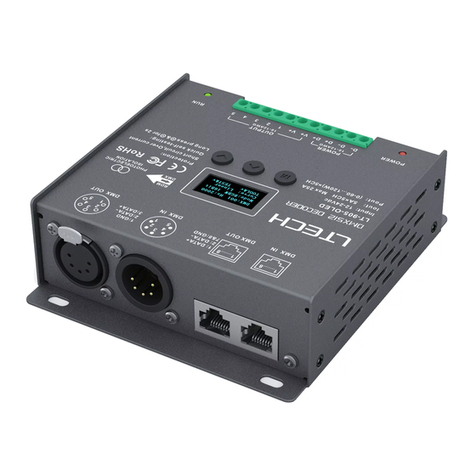
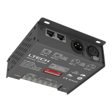
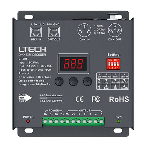
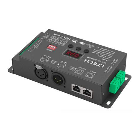
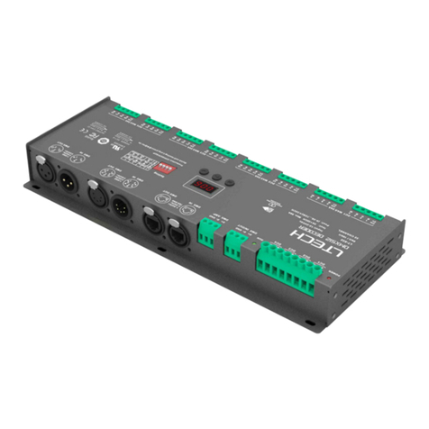
Main component descriptions
Power
indicator
Signal
indicator
12-24Vdc
input voltage
LED lamps
connection
Digital
display
Dip
switch Digital display
Screen
High Smooth
Low Standard
30S off
Enable
PWM Hz DIM
Dip switch
16
Bit
8
RJ45
3-pin XLR
DMX/RDM
input & output
DMX/RDM
input & output
DMX
RDM
DMX
RDM
Wiring diagram
1 Connecting LED lights:
Signal Signal
LED
driver
12-24Vdc
DMX
console
2. DMX console onnectionc :
DMX signal DMX signal
12-24Vdc 12-24Vdc 12-24Vdc
Resistor
terminal
An amplifier is needed if more than 32 decoders are connected ,
signal amplification should not be more than 5 times continuously.
or use overlong signal line
If the recoil effect occurs because of longer signal line or bad line quality, please try to
connect 0.25W 90-120Ω terminal resistor at the end of each line.
LT-903 is equipped with 2 kinds DMX
terminals for users’ selection. The following
diagram takes 3-pin XLR as an example,
the same connecting method for Rj45.
*
*
These 2 terminals can be connected in a mixed way.
Rj45 connected in parallel
3-pin XLR connected in parallel
Terminal
resistor
Terminal
resistor
3. The connection diagram of 2 kinds of DMX/RDM terminals:
*
Installation Attentions : Please reserve enough ventilation distance between decoders ( no less
than 20mm). Be sure not to block the vent, or it may affect the lifetime of decoders for poor
heat dissipation.
Installation distance > 20mm
Vent
RGB LED
RGB LED
DMX signal
LT-903
LT-9 03 LT-90 3 LT-9 03
1
3
2
PUSH
1
3
2
PUSH
GND
DATA+
DATA-
LT-9 03 LT-903 LT-9 03
LT-9 03 LT-903 LT-9 03
Update Time: 31/08/2020_A2
V+
1
2
3
Digital display will enter the locked mode
without operating after 15 seconds.
Long press “M” key to unlock.
Short press “M” key to switch numbers.
Press “ ””v” key to adjust value.
^
M
<
<
888
This manual is subject to changes without further notice.
Product feel free to contact our official distributors if you have any question.
006
