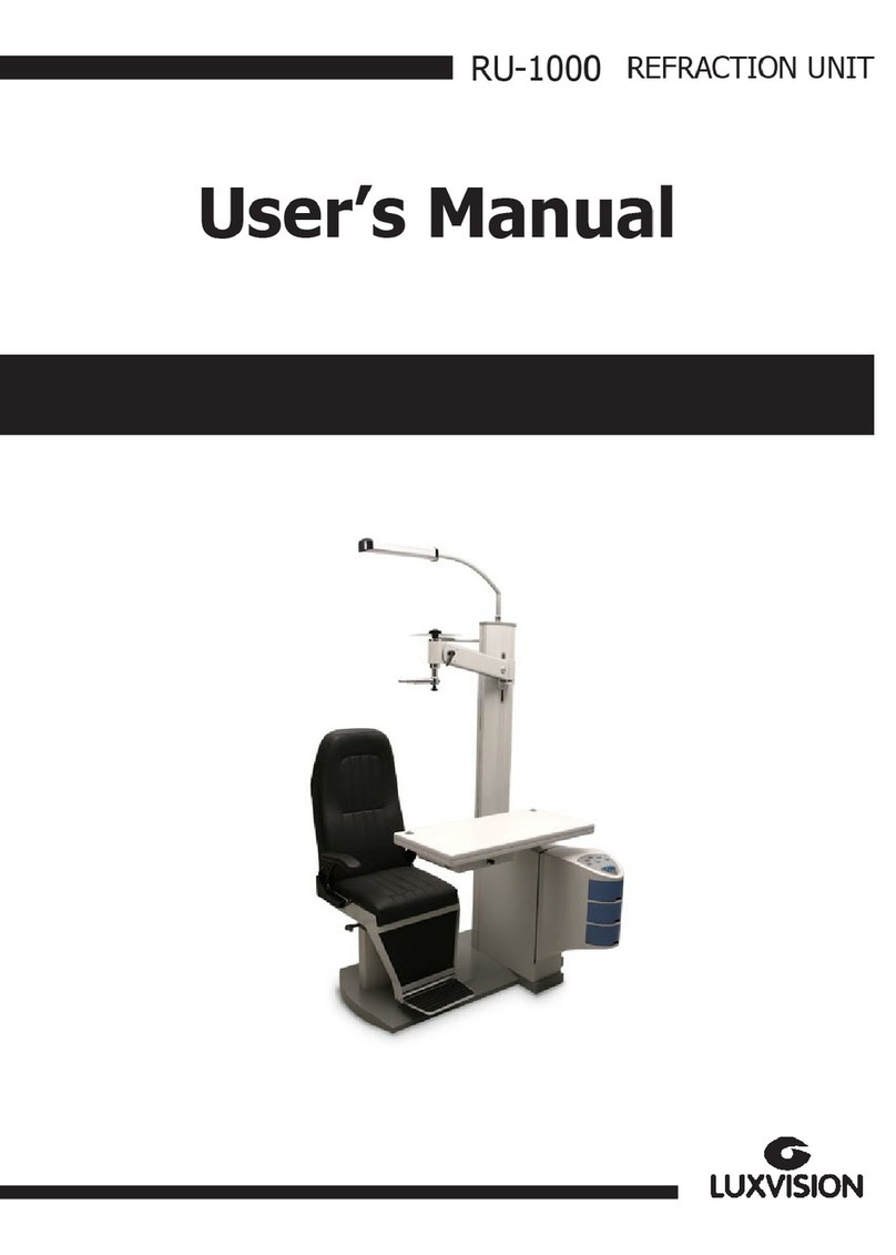
luxvision LRK-7000 User manual

L R K - 70 0 0 A u t o r e f r a c t o r / K e r a t o m e t e r
Operation Manual
LRK-7000

2
Precautions
This product may malfunction due to the electromagnetic wave that is generated from mobile
phone, two-way radio, machinery controlled wireless and others. Do not place any device that may
affect this product nearby.
We believe that the contents of this user manual are accurate in overall since they were reviewed
carefully. However, US Ophthalmic LLC does not assume any kind of responsibility for the latent
mistake or omission that results from the use of information included in this user manual.
US Ophthalmic LLC has the right to make any kind of modification to this product or product specs
anytime without prior notice and modification may not be renewed on this document.
VER1.0
US Ophthalmic LLC
9990 NW 14th ST STE 105 Doral FL 33172

3
! CAUTION
Provision of information on the avoidance of light hazard from the optical device is required in
ISO 15004-2:2007
“Ophthalmic instruments-Fundamental requirements and test methods”
1. The manufacturer shall, on request, provide the user with a graph showing the relative spectral
output of the instrument between 305 nm and 1 100 nm when the instrument is operating at
maximum light intensity and maximum aperture. The spectral output shall be shown for the beam
after it exits the instrument.
LRK-7000
< Spectrum output of all light source during measurement (maximum light intensity) >
2. “CAUTION – The light emitted from this instrument is potentially hazardous. The longer the
duration of exposure, the greater the risk of ocular damage. Exposure to light from this instrument
when operated at maximum intensity will exceed the safety guideline after 1.72 minutes.”

4
CONTENT
1.Introduction..........................................................................................................................................6
1.1.Intended Use.......................................................................................................................................................6
1.2.Equipment overview............................................................................................................................................6
1.3.Grade classification and mentioned items...........................................................................................................6
2.Information regarding safety ..............................................................................................................7
2.1.Introduction.........................................................................................................................................................7
2.2.Safety indication................................................................................................................................................8
2.3.Environment related matters.............................................................................................................................11
2.4.Safety Precautions............................................................................................................................................14
3.Characteristics...................................................................................................................................18
4.Precautions during use.....................................................................................................................19
5.Name and function of each part .......................................................................................................20
5.1.Key part.............................................................................................................................................................20
5.2.Main measurement screen button explanation..................................................................................................24
6.Equipment installation and preparation for measurement............................................................26
7.Measurement Method........................................................................................................................30
8.Measurement......................................................................................................................................37
8.1. Refractive power measurement mode (REF mode).........................................................................................37
8.1.1. Manual measurement mode................................................................................................................................................37
8.1.2. Automatic measurement mode..........................................................................................................................................41
8.1.3. Message List................................................................................................................................................................................42
8.2. Corneal curvature measurement mode (KER mode) .......................................................................................43
8.2.1. Manual measurement mode................................................................................................................................................43
8.2.3. Message List................................................................................................................................................................................46
8.3. Continuous corneal curvature / refractive power measurement mode (K&R mode).........................................47
8.3.1. Manual measurement mode................................................................................................................................................47

5
8.3.2. Automatic measurement mode .........................................................................................................................................49
9.Other mode.........................................................................................................................................50
9.1. SIZE mode (pupil diameter measurement) ......................................................................................................50
9.2. DISPLAY mode................................................................................................................................................53
9.3. User SETUP mode..........................................................................................................................................55
9.3.1. List of setup items & Initial .................................................................................................................................................55
9.3.2. Initial setting...............................................................................................................................................................................55
9.3.3. Detailed description of setting...........................................................................................................................................57
9.4. Input method....................................................................................................................................................66
10.Self-diagnosis and maintenance/repair.........................................................................................68
10.1. REF / KER Accuracy check...........................................................................................................................68
10.2. Replacing.......................................................................................................................................................69
10.2.1 ........................................................................................................................................................................................................69
10.2.2. Chin rest paper .......................................................................................................................................................................70
10.3. Cleaning Equipment.......................................................................................................................................70
10.4. Cleaning.........................................................................................................................................................72
10.4.1. Cleaning the measuring window ....................................................................................................................................72
10.4.2. Cleaning the mire ring ........................................................................................................................................................72
10.4.3. Cleaning the forehead rest and chin rest...................................................................................................................73
10.5. Prior to contact with preferred distributor .......................................................................................................73
10.6. When moving equipment installation place.................................................................................................. 74
11.Information needed for servicing.................................................................................................75
12.Key specs .......................................................................................................................................78
13.Accuracy.........................................................................................................................................81
14.Accessories....................................................................................................................................82
15.EMC Information ............................................................................................................................84
16.Electrical construction diagram ...................................................................................................90

6
1.Introduction
1.1.Intended Use
The Auto Ref/Keratometer LRK-7000 is intended to be used to measure the refractive power of the eye.
1.2.Equipment overview
Automatic eye examination refractive power measurement device, LRK-7000 is the equipment that
measures refractive power of patient’s eyeball to show Sphere (SPH), Cylinder (CYL) and Axis (AXS)
information. Moreover, it can measure test subject’s corneal curvature and PD (Pupillary Distance,
distance between pupils) and pupil’s size. In particular, it is possible to measure Peripheral Corneal
Curvature separately when measuring corneal curvature, and it enables accurate prescription since it is
possible to know the information of the cornea’s center and periphery curvature individually.
1.3. Grade classification and mentioned items
1. Classification of product :
-. EU - Class I with a measuring function according to Annex IX (Rule 12) of the Medical Device
Directive 93/42/EEC
-. KFDA – Class II
2. Resistance against electric shock : Class I (earthed)
3. Protection class against electric : Type B
4. Protection against harmful ingress of water : Ordinary, IPX0
5. Degree of safety in the presence of a flammable anesthetic’s mixture with air or with oxygen or with
nitrous oxide: Not suitable for use in the presence of a flammable anesthetic’s mixture with air or
with oxygen or with nitrous oxide
6. Mode of operation : Continuous

7
2.Information regarding safety
2.1.Introduction
Safety is everyone’s obligation and responsibility. Safe use of this device is important for everyone
involved - installers, users, operators and device managers. It is a must to study and to master this user
manual individually prior to installing, using, cleaning, repairing or controlling this device and its
accessories. It does not suffice to emphasize the importance of understanding the instructions found in
this manual repeatedly in order to increase safety of patient or users. For this reason, the following safety
warning chart is included at the adequate place on this manual in order to highlight information that
requires special precaution or safety related information in particular. All the users or managers need to
pay special attention in addition to mastering “WARNING” or “CAUTION” in the manual.
! WARNING
“Warning” cautions against the existence of calamity that can cause severe personal injury,
death or property loss in case of negligence.
! CAUTION
“Caution” informs of the matters related to calamity that can cause minor injury or property
loss in case of negligence.
! NOTE
“Note” explains important information related to installation, operation and management, and
failure to comply may lead to calamity in case of negligence.

8
2.2.Safety indication
The International Electro technical Commission (IEC) announced the symbols that warn when
connecting electric medical device’s power or that warn against calamity that may occur. Classification
and symbol are as follows.
I and O on power switch represent ON and OFF
respectively.
(O sur l'interrupteur d'alimentation représentent
respectivement ON et OFF.)
Type B Isolated patient connection.
(Type B Connexion patient isolée.)
This symbol identifies a safety note. Ensure you
understand the function of this control before using it.
Control function is described in the appropriate User’s or
Service Manual.
(Ce symbole identifie une note de sécurité. Assurez-vous
de comprendre la fonction de ce contrôle avant de
l'utiliser. La fonction de contrôle est décrite dans le
manuel d'utilisation ou d'entretien approprié.)
It indicates the year of manufacture and the
manufacturer.
(Il indique l'année de fabrication et le fabricant.)
Manufacturer
(Fabricant)
Authorised Representative in the European Community
(Représentant autorisé dans la Communauté
européenne)
Identifies the point where the system safety ground is
fastened to the chassis. Protective earth connected to
conductive parts of Class I equipment for safety
purposes.
(Identifie le point où la terre de sécurité du système est
fixée au châssis. Terre de protection connectée aux
parties conductrices des équipements de classe I à des
fins de sécurité.)

9
Alternating Current
(Courant alternative)
Temperature Limitation
(Limitation de température)
Keep DRY
(Garder au sec)
WEEE mark
Disposal of your old appliance
When this crossed-out wheeled bin symbol is attached
to a product it means the product is covered by the
European Directive 2002/96/EC.
All electrical and electronic products should be disposed
of separately from the municipal waste stream via
designated collection facilities appointed by the
government or the local authorities.
The correct disposal of your old appliance will help
prevent potential negative consequences for the
environment and human health.
For more detailed information about disposal of your old
appliance, please contact your city office, waste disposal
service or the shop where you purchased the product.
(Mise au rebut de votre ancien appareil
Lorsque ce symbole de poubelle barrée est joint à un
produit, cela signifie que le produit est couvert par la
directive européenne 2002/96 / CE.
Tous les produits électriques et électroniques doivent
être éliminés séparément du flux des déchets
municipaux via des installations de collecte désignées
par le gouvernement ou les autorités locales.
L'élimination correcte de votre ancien appareil aidera
à prévenir les conséquences négatives potentielles
sur l'environnement et la santé humaine.Pour plus
d'informations sur l'élimination de votre ancient
appareil, veuillez contacter votre mairie, le service
d'élimination des déchets ou le magasin où vous avez
acheté le produit.)

10
Warning: Crushing or insert of hand
(Attention: écrasement ou insertion de la main)
CE Mark
(Marque CE)
CE for RoHS
RoHS Detective Compliance 2011/65/EU
(CE pôr RoHS
Conformité à la directive RoHS 2011/65 / UE)
Atmospheric pressure limitation
(Limitation de pression atmosphérique)
Humidity limitation
(Limite d'humidité)
Stack direction
(Direction de la pile)
Fragile , handle with care
(Frágil, manipuler avec soin)
Keep away from sunlight
(Tenir à l'écart de la lumière du soleil)
Stack layer limitation
(Limiter la couche de pile)

11
Use no hooks
(N'utilisez aucun crochet)
Consult instructions for use
(Consulter les instructions d'utilisation)
COM Connector cable Symbol
(COM Connector cable Symbole)
Serial Number Symbol
(Symbole du numéro de série)
2.3. Environment related matters
The following environment for operation and storage:
Place where device comes directly into contact with
moisture (do not operate the device with wet hand)
Place where device is exposed directly to sunlight.
A place where the equipment can be exposed to direct
ultraviolet
Place with severe temperature change (temperature
for normal operation ranges from 10 C to 40 C while
humidity level ranges from 30% to 75%).

12
Where there is a hot equipment nearby.
Where the humidity is extremely high or there is a ventilation
problem.
Where the machine is exposed to excessive shocks or
vibrations.
Where the machine is exposed to chemical material or
explosive gas.
Be cautious so that things like dust and metal do not fall
inside the machine.
Don’t disassemble or open the product. US Ophthalmic LLC
does not take responsibility for the possible problems
Be careful not to block the fan of the machine.
Don’t plug the AC power cord into the outlet
unless all parts of the machine are completely
connected. Otherwise, it will cause severe
damage on the machine.
To avoid risk of electric shock, this equipment must
only be connected to a supply main with protective
earth.

13
This instrument must be followed by these following conditions:
As for the environment when using the device, maintain temperature of 10 ~ 40 ℃, humidity level of 30 ~ 75 % and
atmospheric pressure of 800 ~ 1060 hpa.
As for the environment when transporting the device, maintain temperature of -40 ~ 70 ℃, humidity level of 10 ~ 95
%, and atmospheric pressure of 500 ~ 1060 hpa.
As for the environment when storing the device, maintain temperature of –10 ~ 55 ℃, humidity level of 30 ~ 75 %,
and atmospheric pressure of 700 ~ 1060 hpa.
Take precaution so that the device won’t be subjected to excessive shock or vibration.

14
2.4.Safety Precautions
! BEFORE USE, READ THIS MANUAL
The safety precautions and operating procedures must be thoroughly understood prior to
operation of the device.
The device complies with ISO 10342 subclause 4: 2010 (Ophthalmic instruments – Eye
Refractometers) and ISO 10343 subclause 4: 2009 (Ophthalmic instruments -
Ophthalmometers). The dioptric powers are indicated with reference wavelength λd = 546.07
nm or λd = 587.56 nm
This device was developed and proven according to the domestic and international safety specs. This
guarantees this device’s high safety level. By law, a manufacturer is obligated to provide sufficient
explanation of the matters pertaining to the device safety to device users. Likewise, compliance with the
contents of this device’s manual is mandatory for safety sake. Thus, read the instructions in the manual
sufficiently and understand prior to turning on the power. For many more information, inquire the
distributor where you purchased the device.
1. Do not store or install this device at the following places; (a) place that runs the risk of exploding, or
(b) place that has volatile chemical substance such as alcohol benzene or inflammable and
explosive material.
2. Do not store or install at a humid place. To ensure normal operation, humidity level should range
between 30 and 75%. The device should not be exposed to a place where water splashes
significantly, water falls off, or gets sprayed. Do not place the container with liquid or gas on top of
the device.
3. This device should be operated by qualified personnel with sufficient training or under such
personnel’s supervision.
4. This device can be modified only by US Ophthalmic LLC service technician or a person with
comparable qualifications.

15
5. Device management by customer should be carried out as explained in the user or service manual.
Management that requires more sophisticated skill set can be carried out only by US Ophthalmic
LLC service technician or a person with comparable qualifications.
6. Manufacturer assumes responsibility for this device’s safety, reliability and performance only when
the following conditions are satisfied: (1) When this device was installed at a viable space in
accordance to this manual’s regulations, and (2) when this device was used and maintained
according to the procedure regulated in this manual or service manual.
7. Manufacturer does not take responsibility for the damage resulting from this device’s unlawful
modification. However, device’s unlawful modification becomes a factor for losing the right to get
warranty during the warranty period.
8. This device is utilized with the accessories provided by US Ophthalmic LLC. If consumer wants to
use other manufacturers’ accessories, safety of use must be proven and confirmed by US
Ophthalmic LLC or by the accessories’ manufacturer.
9. Only a person who completed adequate training or education program can install, operate and
maintain this device.
10. Store user or service manual at a place that is readily accessible by the person who manages and
uses this device.
11. Do not exert force on the cable connection. If cable does not get connected easily, then check whether connecter (plug) is suitable for the socket.
When connector or socket is damaged, qualified service
technician needs to repair it.
12. Do not pull on the device’s cable. Hold on the plug to take out to open up the cable.
13. This device can be used according to this manual in relation to the refractive power, corneal
curvature measurement and their application.
14. Always test the state of the device’s external appearance and check whether it is functioning well
before using the device.

16
15. Do not block device’s hole for heat radiation.
16. Turn off the power immediately and take out the plug when there is smoke, spark, abnormal noise
or smell.
17. IEC standard needs to be satisfied with in order to connect an outside device with input/output signal
or other connector. (IT equipment is IEC 60950, and electric equipment for medical use is IEC
60601). Moreover, all the systems need to satisfy the safety requirement, IEC 60601-1 when it
comes to the electric system for medical use. Person who connects outside device with input/output
signal or other connector has the obligation to take responsibility in accordance to the IEC60601-1.
Contact local technician or distributor if you have doubts.
18. This equipment may cause edge which is hazardous for other devices at the periphery. Wireless
frequency may be generated or used, and energy may be released when the device is not installed
or used according to the guideline. However, there is no guarantee that edge does not result when
carrying out specific installation. If this device leads to hazardous interception on other device when
the equipment is turned on/off, user needs to solve the interception issue by using one of the
following measures.
- Change direction or relocate the receiver
- Distance between equipment is increased
- Connect the equipment with the socket of the circuit connected with other device and other
circuit
- Ask manufacturing business or field service technician for help
19. To avoid electrocution, this device must be connected to the supply power along with protective
grounding.
20. Do not place at a difficult location when separating cable when it comes to the device’s placement.
21. When you carry this product, please hold on left and right bottom of the product. If you want the
product to be installed on another place, please call A/S center.

17
! CAUTION
For use of equipment in rated voltage less than 125Vac, minimum 6A, Type SJT or SVT,
18/3AWG, 10A, max 3.0m long: One end with Hospital Grade Type, NEMA 5-15P Other end
with appliance coupler. For use of equipment in rated voltage less than 250Vac, minimum 6A,
Type SJT or SVT, 18/3AWG, 10A, max 3.0m long: One end terminated with blade attachment
plug (HAR) Type, NEMA 6-15P.
This equipment must be installed and operated in accordance with provided instructions and
the antenna(s) used for this transmitter must be installed to provide a separation distance of
at least 20 cm from all persons and must not be co-located or operating in conjunction with
any other antenna or transmitter. End-users and installers must be provide with antenna
installation instructions and transmitter operating conditions for satisfying RF exposure
compliance.

18
3.Characteristics
1. It is possible to carry out both refractive power and corneal curvature measurement with one
machine.
2. It is possible to measure even the myopia since the refractive power measurement range is very
broad ranging from –30 D to +25 D.
3. When measuring refractive power, it is possible to measure up to a minimum pupil diameter Ø2.0
mm.
4. Fog and mist technique that is applied to the internal fixation Target enables increasingly accurate
measurement by ensuring natural and comforting feel for the patient’s eyes.
5. Cornea measurement’s marking form and cornea equivalence curve rate can be selected.
6. Distance between pupils (PD) measurement is enabled.
7. It is possible to observe the state of cataract patient’s eyes or scratch on the contact lens surface
through light observation with Retro-Illumination. It is possible to store up to two images of the left/right
eyes in the memory. Stored image can be output on the monitor screen again to show to the patient.

19
4.Precautions during use
1. Handle with care since shock can damage the outside or the inside.
2. Precision measurement may be affected when the product is exposed to direct sunlight or too bright
indoor illumination. It is recommended to measure at a dark eye examination room.
3. Get guidance at the place of purchase when using the device by connecting with other equipment.
4. When heating up the inside at a cold area all of the sudden, vapor may result on the object lens of the
customer side and on the optical parts at the inside of the device. In this case, measure after waiting
for the vapor to disappear.
5. Main the object lens from the customer side that is subjected to the test clean at all times. Error may
result or precision measurement may be affected if tainted with dust or alien substance.
6. Take out the power plug to separate the power when there is smoke, smell or noise during use. Then,
follow the instructions of the place of purchase.
7. Do not use alcohol, thinner, benzene and organic solvent to clean this equipment’s surface since
these may damage the equipment.
8. When moving the LRK-7000, turn off the power switch always, and fixate the stage. Then, move by
lifting up with lower part of the body with both hands.
9. When LRK-7000 is not used for a long time, separate the power and cover it with the dust cover.
10. When using this equipment under normal state, then the proper location is as shown below.

20
5.Name and function of each part
5.1.Key part
1
6
4
5
7
3
2
[Front part]
This manual suits for next models
1
Table of contents
Other luxvision Medical Equipment manuals
Popular Medical Equipment manuals by other brands

Storz
Storz TP012 instruction manual

Atmos
Atmos E 201 Thorax Short operating instructions

Mercoframes Optical Corp
Mercoframes Optical Corp Kowa KT-800 instruction manual

Limacorporate
Limacorporate SMR Axioma TT Metal Back Glenoid Bone... Disassembly and Assembly Instructions

Anspach
Anspach SHORT-G1 Assembly and Disassembly

natus
natus XLTEK EEG32 User and service manual