mectron COMPACT PIEZO LED User manual

INSTALLATION MANUAL
compact piezo LED
U.S. Federal law restricts this device to sale by or on
the order of a licensed dentist or dental hygienist.
00510051

COMPACT PIEZO LED

I
Copyright
© Mectron S.p.A. 2022. All rights reserved. No part of this document can be reproduced in any
form without the written consent of the copyright owner.

II
COMPACT PIEZO LED
TABLE OF CONTENTS
1 Introduction 1
1.1 Intended Use 1
1.2 Description of the Device 2
1.3 Disclaimer 2
1.4 Safety Precautions 3
1.5 Symbols 5
2 IdenticationData 6
2.1 DeviceIdenticationLabel 6
2.2 HandpieceIdenticationData 7
2.3 InsertTipsIdenticationData 7
3 Delivery 8
3.1 List of Components 8
4 Installation 11
4.1 Safety precautions During Installation 11
4.2 Mechanical Installation 12
4.3 Electrical Connections 13
4.3.1 Alternate 24V Power Supply 14
4.3.2 Direct 32V Power Supply 14
4.3.3 Power Regulation 15
4.3.3.1 Power Regulation with 2.2 kOhm Potentiometer 15
4.3.3.2 Power Regulation with 10 kOhm Potentiometer 15
4.3.3.3 PowerRegulationwith4.7kOhmPotentiometer 15
4.3.3.4 0-5VPowerRegulation 16
4.3.3.5 0-10VPowerRegulation 16
4.3.4 SolenoidValveControl 16
4.3.5 Enabling 17
4.3.5.1 EnablingofPedalwithNegativeSignal 17
4.3.5.2 EnablingofPedalwithPositiveSignal 17
4.3.6 OtherConnections 17
4.3.7 ConnectingtheCordoftheScalerHandpiece 18
4.3.8 Standard Connections 18
4.3.8.1 Layout A 19
4.3.8.2 Layout B 19
4.3.8.3 Layout C 20
4.3.8.4 Layout D 20
4.3.8.5 Layout E 21
4.3.8.6 LayoutF 21
4.3.8.7 LayoutG 22
4.3.8.8 Layout H 22
4.4 Water Connection 23
5 MethodsandPrecautionsforDisposal 24
6 TechnicalData 24
6.1 ElectromagneticCompatibilityIEC/EN60601-1-2 26
6.1.1 GuidanceandManufacturer’sDeclaration-ElectromagneticEmissions 26
6.1.2 AccessiblePartsoftheCasing 27
6.1.3 GuidanceandManufacturer’sDeclaration-ElectromagneticImmunity 28
6.1.3.1 A.C.InputPowerConnection 28
6.1.3.2 PointsofContactwiththePatient 30
6.1.3.3 PartsAccessibletotheInput/OutputSignals 31
6.1.4 SpecicationsoftheTestsfortheImmunityoftheAccessiblePartsofthe

IV
COMPACT PIEZO LED
PAGEINTENTIONALLYLEFTBLANK

1
INTRODUCTION
1 INTRODUCTION
1 https://manuals.mectron.com/
Read this manual and follow its instructions
carefully before proceeding with the
installation, use, maintenance, or other
operations on the device. Please always keep
this manual within easy reach.
IMPORTANT: to avoid potential serious
injurytotheuserandthepatientand/
or this device or other equipments, read
all the “Safety precautions” present in the
manual with particular attention. The words
WARNING, CAUTION and NOTE contained
in this document, carry special meaning
and must be carefully reviewed. Depending
on their degree of seriousness, the safety
precautionsareclassied:
WARNING:(Identiesconditionsor
practices that present a risk of serious injury
ordeathtothepatientand/ortheuser.)
CAUTION:(Identiesconditionsor
practices that could result in minor injury or
devicedamage.)
NOTE:Identiesspecialinformationtoclarify
or emphasize important instructions.
The purpose of this manual is to make
the operator knowledgeable of the safety
precautions and the instructions for a correct
installation and maintenance of the device
and its accessories.
Use of this manual for purposes other than
those strictly tied to the installation and
maintenance of the device is forbidden.
The information and illustrations in this
manual are updated as of the date of issue
reported on the last page.
Mectron is committed to continuously update
its products with possible modications to
device components.
In case you encounter discrepancies between
the descriptions found in this manual and the
device in your possession you can:
• check for any available updates in
the
section MANUALS of MECTRON
website
1
;
• askclaricationstoYourDealer;
• contact Piezosurgery Inc. After Sales
Service.
1.1 IntendedUse
The compact piezo LED is an ultrasonic piezoelectric scaler intended for use, with the appropriate
associated insert tips, in the following dental applications:
• Scaling: Procedures for removal
ofsupra-gingival/sub-gingivaland
interdentalcalculus/plaquedeposits;
• Periodontology: Periodontal therapy
and debridement for all types of
periodontal diseases, including
periodontal pocket irrigation and
cleaning;
• Endodontics: All treatments for root
canal reaming, irrigation, revision,
lling,guttaperchacondensationand
retrograde preparation;
• RestorativeandProsthetics:
Restorative procedures including cavity
preparation, removal of prostheses,
amalgamcondensation,nishing
ofcrownpreparations,inlay/onlay
condensation,implants/restorations
cleaning.
WARNING: The device must be used
in a dental practice, in a clinic, or in a
professional oral hygiene and preventive
care centres. Do not use the device in
environments where the atmosphere
issaturatedwithammablegases
(anaestheticmixtures,oxygen,etc.).

2
COMPACT PIEZO LED
WARNING: Qualiedandspecialized
personnel.The device is intended exclusively
for use by a dentist, or dental hygienist, with
suitablemedical/healthtraining.The use of
thedevicedoesnotcausesideeectsifitis
used correctly. An improper use might cause
tissues heating.
WARNING: IntendedUse. Use the
device only for the intended use.
Failuretoobservethisprecautionmaycause
serious injuries to the patient, the operator,
anddamages/breakdownstothedevice.
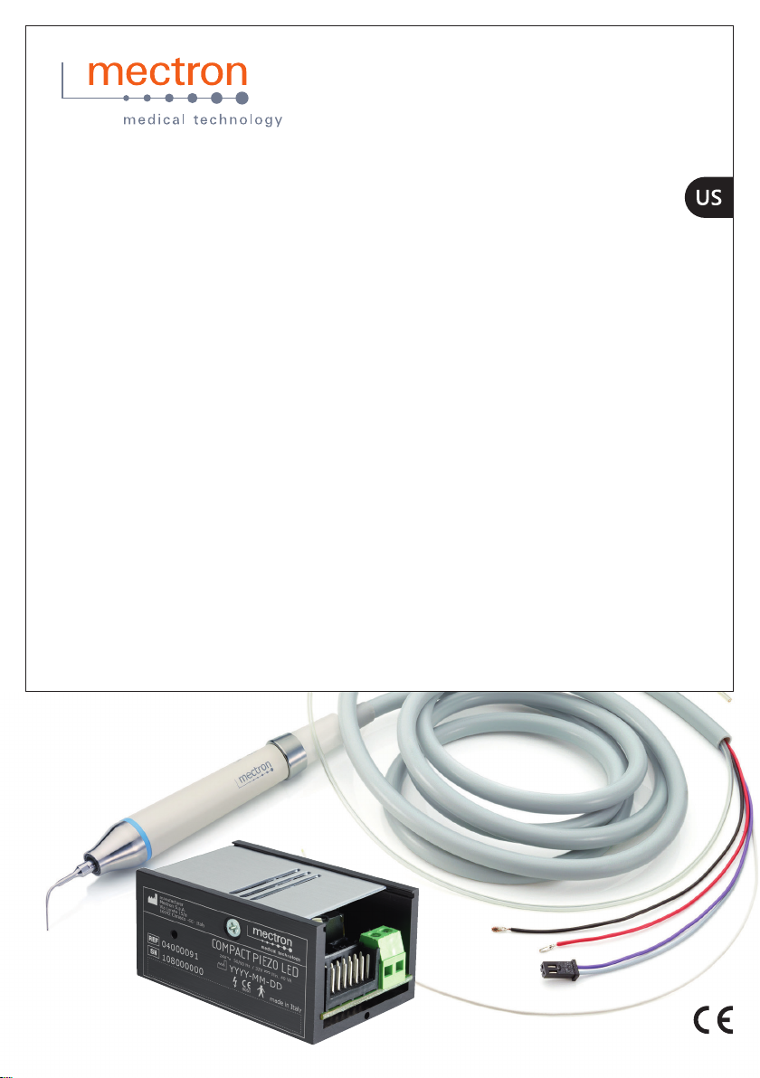
1.2 DescriptionoftheDevice
compact piezo LED is a multifunctional
ultrasonic piezoelectric scaler. It has been
designed in order to oer a product with
innovative design and exclusive technical
characteristics to the operator, and maximum
comfort during the treatment to the patient
thanks to a wide range of possible power
settings.
The device has an automatic sync circuit
which optimizes frequency and power for
each available insert tip, so that the best
performance is always assured. The handpiece
has a circular LED light and can be autoclaved
at 135 °C.
1.3 Disclaimer
The manufacturer Mectron disclaim any
liability, expressed or implied, and shall have
no responsibility for any direct, indirect or
other damages and personal injury arising out
in connection with any errors in the use of the
device and its accessories.
The manufacturer Mectron shall be under no
liability, expressed or implied, with respect to
anydamages(personalinjuryand/ordamage
toproperty)which mightariseorbecaused,
whether by the customer or by any of the
users of the product and its accessories, as
result of:
• Useorproceduresdierentthanthose
speciedintheintendeduseofthe
product;
• The environmental conditions for the
preservation and storage of the device
are not compliant to the precautions
indicated in the
Chapter6onpage24
;
• The device is not used in compliance
with all the instructions and precautions
described in this manual;
• The electrical system in the premises in
which the device is used is not compliant
to the norms in force and to the relative
precautions;
• The assembly operations, extensions,
adjustments, updates, and repairs on the
device are performed by personnel not
authorized by Piezosurgery Inc.;
• Misuse, abuse, abnormal use, negligent
use, intentional misconduct or use
exceeding the limits of the device
indicatedandallowedand/ornormal
wearordeterioration,illtreatmentand/
or incorrect interventions;
• Any and all attempts to tamper with
or modify the device, under any
circumstance;
• Use of non-original Mectron insert
tipsthatentailanitedamageto
the threading of the handpiece, thus
compromising correct operation and
causing risk of harm to the patient;
• Use of non-original Mectron insert tips,
used in accordance to designed and
tested settings of Mectron original insert
tips. The correct use of the settings is
guaranteed only with original Mectron
insert tips;
• Lack of stock materials (handpiece,
inserttips,wrenches)tobeusedinthe
event of device stop due to fault or of
inconveniences;
• Incorrect/omittedmaintenance
compared to what is stated in
Chapter7
on page 33
of this manual;

3
INTRODUCTION
• Breach of the requirements and the
information contained in
Chapter 4.5 on
page 14
of the Use and Maintenance
Manual;
• Breach of the requirements and the
information contained in
Chapter6on
page 17
of the Use and Maintenance
Manual;
• Unauthorized repairs in accordance with
the indications contained in
Chapter7.3
on page 36
of this manual.
1.4 SafetyPrecautions
WARNING: Contraindications.
Do not use the device on patients who
carryheartstimulators(Pace-makers)or
other implantable electronic devices. This
precaution also applies to the operator.
WARNING: Contraindications. Do not
perform scaling treatments without water
spray in order to avoid the insert tip over-
heating which may cause damages to the
tooth. Treatments with no water spray can be
carried out only with “Dry Work” insert tips
which do not have the water passage.
CAUTION: Contraindications.
Ultrasonicscaler. Do not perform treatments
on prosthetic artifacts made of metal or
ceramics. The ultrasonic vibrations could lead
to the de-cementing of the artifacts.
WARNING: Contraindications.
Interferencefromotherequipment.
An electrical scalpel or other electro-surgical
units near the compact piezo LED device may
interfere with its correct operation.
WARNING: Contraindications.
Interferencewithotherequipment.
ThoughcomplianttothestandardIEC60601-
1-2, compact piezo LED may nonetheless
interfere with other devices nearby.
compact piezo LED must not be used near
to or stacked on other devices. However,
if this were to prove necessary, check and
monitor correct operation of the device in
thatconguration.
WARNING: Riskofexplosion. The
device cannot operate in environments where
theatmosphereissaturatedwithammable
gases(anestheticmixtures,oxygen,etc..).
CAUTION: In case the end user, when
operating in his or her own medical study
or clinic, must subject the electro-medical
equipment and systems to periodical
inspections in order to adhere to imposed
requirements, the test procedures that must
be applied to electro-medical equipment
and systems to evaluate safety must be
performedinlinewiththestandardEN62353
‘Medical electrical equipment - Periodic
inspections and tests to be carried out after
repairofmedicalelectricalequipment’.The
frequency of periodic inspections in the
intended conditions of use described is
once per year or every 2000 hours of use,
whicheverconditionissatisedrst.
WARNING: Checkingdevicestatus
beforethetreatment. Before every
treatment, always check that the device
works perfectly and that the accessories are
ecient.Incaseofoperatingabnormalities,
DO NOT perform the treatment. Contact an
Authorized Piezosurgery Inc. Service Center if
the abnormalities concern the device.
WARNING: Cleaningandsterilising
neworrepairedinstruments. All the new
or repaired device accessories are not sterile.
Atrstuseandaftereachtreatmentthey
must be cleaned and sterilized by carefully
following the instructions in
Chapter6on
page 17
of the Use and Maintenance
Manual.
WARNING: Diamond coated insert tips
are SINGLEUSEONLY. The diamond coated
insert tips are intended to be used on an
individual patient during a single treatment
procedure and then disposed of. The
diamond coated insert tips must be sterilized
onlyonetime,priortherstuse.

4
COMPACT PIEZO LED
WARNING: Infectionscontrol.
To ensure maximum safety of the patient and
the operator, before using all the reusable
parts and accessories, make sure you have
rstcleanedandsterilizedthem,following
the instructions of the
Chapter6onpage
17
of the Use and Maintenance Manual.
CAUTION: Contraindications. Allow
reusable, autoclavable items (the handpiece,
the insert tips, the torque wrench, and any
otheraccessorythatcanbesterilized)to
gradually return to room temperature after
steam sterilization and prior to usage. The
cooling process must not be accelerated.
WARNING: Breakageandwear-outof
the insert tips. High frequency oscillations
and wear-out may, in rare circumstances, lead
to the breakage of the insert tip.
Deformed or otherwise damaged insert tips
are susceptible to breakage during their use.
These insert tips must never be used.
If an insert tip breaks, check that none of its
fragments remain in the treated part and,
atthesametime,applyeectivesuctionto
remove them.
The patient must be instructed to breathe
through his nose during the treatment, or
a dental dam must be used to prevent the
patient from ingesting fragments of broken
insert tips.
Check the level of wear of the insert tip and
its integrity before and during each use. If
there is a decrease in performance, replace
it. The level of wear of the most common
inserttips(S1,S1-S,S2,S5,P2,P4,P10)can
be checked by using the INSERT TIP - CARD
supplied. To use the INSERT TIP - CARD
correctly:
• Position the insert tip on the INSERT
TIP-CARDsothattheprolematches
theoneprintedonthecard.Theprole
printed on the card has a red line
indicating the wear limit;
• If the insert tip has a length less than
the wear limit, its performance will be
signicantlylowerthanthecondition
of a new one and replacement is
recommended.
If the layer of titanium nitride (golden
surface),wherepresent,isvisiblyworn,the
insert tip must be replaced. The use of a worn
inserttipdecreasesitseciency.
When the nitride coating wears out, the
cuttingeciencydecreases;re-sharpening
the insert tip damages it and is therefore
forbidden. Check that the insert tip is not
worn out.
During the intervention, frequently check that
the insert tip is intact, especially in its apical
part.
During the intervention, avoid prolonged
contact with retractors or with metallic
instrumentation in use. Do not exert excessive
pressure on the insert tips during their use.
WARNING: OnlyuseoriginalMECTRON
inserttips,accessories,andspareparts.
CAUTION:Nomodicationofthis
equipment is allowed.
WARNING: Prior to any use, system
components must be inspected for damage.
Do not use if damage is apparent.
WARNING: Do not operate the device if
handpiece is defective, damaged or broken.
Immediately replace the handpiece.
NOTE: In case of accident attributable to the
device during correct use and in accordance
with the intended use, a report must be
made to the Competent Authority and
manufacturer indicated on the product label.

5
INTRODUCTION
1.5 Symbols
Symbol Description Symbol Description
0051
Device compliant
withRegulation(EU)
2017/745.Notied
body:IMQS.p.A.
MEMKO Mark
UL-CSA compliance
CAUTION, See
instructions for use.
Consult instructions
for use
Manufacturer Date of manufacture
YYYY
Manufacturer, year of
manufacture included
(YYYY=year)
Serial Number
Lot Number Product Number
Single-Use Expiring date
Non-sterile
Can be sterilized in
autoclave up to a
maximum temperature
of 135° C
Applied part of type
“B”asperEN60601-1
recommendation
Alternating current
Direct Current Dangerous voltage
The device and its
accessories must not be
disposed of or treated
as solid urban wastes
Genericwarning
indication a)
Temperature limitation
- transport and storage
conditions
Humidity limitation -
transport and storage
conditions
Atmospheric pressure
limitation - transport
and storage conditions
QTY.1 Quantityofitemsinthe
package: 1

6
COMPACT PIEZO LED
Symbol Description Symbol Description
Rx Only
ForUSmarket,only.
CAUTION:U.S.Federal
law restricts this device
to sale by or on the
order of a licensed
dentistand/ordental
hygenist.
Table1 – Symbol a) The symbol is represented by a yellow warning
triangle and a black graphical symbol.
2 IDENTIFICATIONDATA
A correct description of the model and of the
serial number of the device will allow the After
Sales Service to provide fast and eective
answers.
Always provide this information every time
that you contact Piezosurgery Inc. After Sales
Service.
2.1 DeviceIdenticationLabel
Each device is equipped with an
identication label indicating the main
technical characteristics and the serial
number. The ID label is located on the
side of the compact piezo LED module.
Thecompletetechnicalspecicationsare
provided in
Chapter6onpage24
.
NOTE: The complete list of symbols is
provided in
Capitolo 1.5 a pagina 5
.
COMPACT PIEZO LED
108000000madein Italy
manufacturer
Mectron S.p.A.
Via Loreto 15/a
16042 Carasco -GE- Italy
0051
04000091YYYY-MM-DD
24V 50/60 Hz / 32V Min. 40 VA
Bar Code HIBC 128
Additional symbols and characteristics
of the device are provided on a separate
label. This ID label is located on the side
of the compact piezo LED module.
NOTE: The complete list of symbols is
provided in
Capitolo 1.5 a pagina 5
.
Protect with Fuse T 2AL, 250V
Use only with adapters or similar as indicated in
the instruction manual.
Device for intermittent operation:
60 s ON - 30 s OFF with irrigation
30 s ON - 120 s OFF without irrigation
COMPACT PIEZO LED

7
IDENTIFICATIONDATA
2.2 HandpieceIdenticationData
The handpiece name, MECTRON logo,
serial number, product code, HIBC matrix
code, and a series of symbols are laser
engraved on the scaler handpiece.
NOTE: The complete list of symbols is
provided in
Chapter 1.5 on page 5
.
YYYY-MM
YYYY-MM
0476
0051
114000000
03120000
107000000
03120238
114000000
03120238
0476 0476
0051
0051
YYYY-MM
MANIPOLO ABLATORE
SLIM
MANIPOLO ABLATORE
SLIM
MANIPOLO ABLATORE
SLIM
114000000
03120238
0476
0051 YYYY-MM
MANIPOLO ABLATORE
SLIM Data Matrix
HIBC 128
2.3 InsertTipsIdenticationData
On each insert tip is laser-marked the
name the insert tip itself (Reference 2),
the MECTRON logo (Reference 3) and
the lot number to which the insert tip
belongs(Reference4).
2 3 4

8
COMPACT PIEZO LED
3 DELIVERY
3.1 ListofComponents
See
Figure1apagina10.
compact piezo LED is supplied with the
standard equipment (see Table 2 a pagina
8), a set of variable accessories depending
onthecongurationandclientrequests(see
Table 3 a pagina 9), and accessories that
can be ordered separately (see Table 4 a
pagina 9).
NOTE: Both the items included in the
standard supply and all accessories can be
ordered separately by the client.
Standardsupply
Item Code Description Ref.
Device core unit 04000091 A
Cord 02830086 B
Scaler Handpiece 03120238 MANIPOLO ABLATORE SLIM
(SLIMSCALERHANDPIECE) C
Use and Maintenance Manual 02150290 US version
DInstallation Manual 02150291 US version
Information: Online
Documentation 02150650
Table2 – Standard supply.
Accessoriesavailablefororderwithstandardsupply
Item Code Description Ref.
Torque wrench 02900137 K10 torque wrench b) E
Inserts 0296xxxx "S” series reusable scaler inserts b) F
0308xxxx “PE” series reusable scaler inserts
b)
0305xxxx “R” series reusable scaler inserts b)
0345xxxx “ER” series reusable scaler inserts
b)

9
DELIVERY
Accessoriesavailablefororderwithstandardsupply
Item Code Description Ref.
0235xxxx “E” series reusable scaler inserts b)
0299xxxx “D” series reusable scaler inserts
b)
0219xxxx “CM” series reusable scaler
inserts b)
03570004 “ICS” series reusable base insert b)
03590009 "IC1" tip b)
02900112 IC1tipskit(5pcs.)b)
Wiring
01560022 Layout A b)
G
01560023 Layout B b)
Table3 – Accessories available for order with standard supply.
Accessoriesavailableforseparateorder
Item Code Description Ref.
Scaler Handpiece 03120142 MANIPOLO ABLATORE LED (LED
SCALERHANDPIECE)
b) H
FrontconeforLEDhandpiece 03020158 FrontconeforLEDSCALER
HANDPIECE
b) I
Frontconewithoutlight 03020171 Front cone for LED SCALER
HANDPIECE b) J
Light guide kit 02900146
Front cone, light guide and
decorative ring for SLIM scaler
handpiece b)
K
Table4 – Accessories available for separate order.
b) Produced by Mectron.

10
COMPACT PIEZO LED
The packaging of the appliance cannot
undergo strong impacts as contains electronic
components, therefore the transport and the
storage must be carried out with particular
care.
All the material sent by MECTRON was
controlled at the time of dispatch.
The appliance is shipped appropriately
protected and packaged.
Upon receipt of the appliance, check for any
possible damage caused during transport and
incase anydamage and/ordefectsisfound,
complain to the transporter.
Keep the packaging in case any items need to
be sent to an Authorised MECTRON Service
Centre and to store the appliance during long
periods of non-use.
WARNING: Before starting the treatment,
always make sure to have a stock of material
(handpiece,inserts,wrenches)touseinthe
event of failures or drawbacks.
E
I J K
F
D
A
G H
B C
x 3
Figure1 – List of components

11
INSTALLATION
4 INSTALLATION
compact piezo LED, in order to operate must
be connected to a dental unit.
The dental unit mechanically houses the pilot
module, supplies power to the module, and
supplies water to cool the handpieces and
inserts.
The dental unit to which compact piezo LED
is connected must be a medical device that
complies with general and applicable product
regulationsforthespeciccategoryofdental
unit, and in general, satisfy the following
standards:
• ISO7494Dentistry–Stationarydental
units and dental patient chairs;
• ISO60601-1Medicalelectrical
equipment–Part1:General
requirements for basic safety and
essential performance.
NOTE: Check that the dental unit to which
compactpiezoLEDisconnectedsatisesthe
speciedrequirements.
4.1 SafetyprecautionsDuringInstallation
CAUTION: The voltage of the electric
power supply to which the device will be
connected must be compatible with the
devicetechnicalspecications(see
Chapter
6onpage24
)andthechosenconnection
diagram.
CAUTION: Use a power supply
conformingtoIEC/EN60601-1withthe
following characteristics:
• 24V~50/60Hzor
• 32 V with a minimum power of 40VA.
CAUTION: DONOT invert, for any
reason, the position of the red and black
wires on the connector of the scaler
handpiece (
Figure4atpage18
).
CAUTION:Do not wire the red and black
wires of the scaler handpiece cord (see
Figure
4 at page 18
)togetherwithotherwires.
CAUTION: If long connections are
needed for the power supply, use wires of
adequate section, for example 1.5 mm2.
CAUTION: The water hose of the scaler
handpiece cord must be directly connected
to the dental unit cold water circuit.
WARNING: Install the device in a safe
place protected from impact or accidental
water or liquid spray.
WARNING: Do not install the device
above or near sources of heat. Arrange
during installation for a suitable circulation of
air around the device.
CAUTION: The electrical system of the
premises in which the device is installed
and used must be compliant to the norms
in force and to the relative electrical safety
precautions.
WARNING: The technician or the
manufacturer of the dental chair on which
the compact piezo LED has been installed
is responsible for the compliance of the
productandoftheentiresystemtotheIEC/
EN60601-1inlaw.
WARNING: Contraindications.
Interferencewithotherequipment.
ThoughcomplianttothestandardIEC60601-
1-2, compact piezo LED may nonetheless
interfere with other devices nearby.
compact piezo LED must not be used near
to or stacked on other devices. However,
if this were to prove necessary, check and
monitor correct operation of the device in
thatconguration.
WARNING: Contraindications.
Interferencefromotherequipment.
An electrical scalpel or other electro-surgical
units near the compact piezo LED device may
interfere with its correct operation.

12
COMPACT PIEZO LED
CAUTION: In the case that the end
user, when operating in his or her own
medical study or clinic, must subject the
electro-medical equipment and systems to
periodical inspections in order to adhere to
imposed requirements, the test procedures
that must be applied to electro-medical
equipment and systems to evaluate safety
must be performed in line with norm EN
62353‘Electro-medicaldevices-Periodical
inspections and tests to be performed after
repair interventions on electro-medical
devices’.Theintervalforperiodicchecks,in
the intended operating conditions is one year
or 2000 hours of use, depending on which of
thesetwoconditionsoccursrst.
WARNING: Riskofexplosion.
The device cannot operate in environments
where there are saturated atmospheres of
ammablegases(aestheticmixtures,oxygen,
etc.).
CAUTION: Theelectricalcontactsinside
thecordandhandpiececonnectorsmust
be dry. Before connecting the handpiece to
its cord, check that the electrical contacts are
perfectly dry, on both parts. If necessary dry
them with compressed air.
WARNING:OnlyuseoriginalMectron
inserttips,accessories,andspareparts.
CAUTION: It is prohibited to make any
changes to the device.
4.2 MechanicalInstallation
Figure2apagina12 shows the dimensions of the module.
The module can be secured to the dental unit by means of two M3 threaded holes (Ref. A and
B),oralternatively,bymeansoftwoholeswithdiameter2mm(Ref.CandD).
WARNING: The M3 screw used to secure
the module must not penetrate the inside of
said module for more than 4mm as it may
damage the circuits.
The holes with diameter 2 mm have a
maximumdepthof6mm.
The module is also supplied with holes on the
sides, but these must NOT be used to secure
it. The holes on the sides are used to attach
several internal components.
5,0012,00
70,00
36,50
46,00
2,00
2,00
42,00
M3
M3
23,00
34,00
A
A
B
B
C
C
D
D
MAX
4,00
M3
MAX
6,00
2,00 2,00
Figure2 – Dimensions of the module.

13
INSTALLATION
4.3 ElectricalConnections
compact piezo LED allows various electrical
congurationstosatisfythecharacteristicsof
the dental unit in which it is housed.
The dental units to which the
compact piezo LED device can be connected
must be able to provide one of the following
power supplies:
• 24V~50/60Hzor
• 32 V
with minimum power 40VA.
Moreover, it must have a 2A, 250V safety fuse.
Fortheelectricalconnections,the
compact piezo LED device is equipped with 2
connectors (see
Figure3apagina13
):
• M1 : connector with 2x8 contacts for the
module controls;
• M2 : connector with 2 contacts for
connection of the handpiece cable
(piezoelectricelementscontrol);
• M3 : connector with 2 contacts for
connection of the handpiece cable (LED
control).
M1
M3
M2
M1
M2
1 21 2 3 4 5 6 7 8
16 15 14 13 12 11 10 9
16 15 14
1 2
M3
Figure3 – Module connectors.
M1ConnectorPin-Out
Pin Signal Pin Signal
1 Reserved 9 Bypass capacity
2 RIS 10 GND
3 TX 11 Pedal +
4 RX 12 Power Selection
5 Valve 13 AC In
6Power Control 14 AC/DCIn
7Pedal - 15 GND
8 +Vdc 16 Reserved
Table5 – M1 Connector Pin-Out.

14
COMPACT PIEZO LED
M2ConnectorPin-Out
Pin Signal
1 Vout handpiece
2 Neutral
Table6 – M2 Connector Pin-Out.
M3ConnectorPin-Out
Pin Signal
1 LED A
2 LED K
Table7 – M3 Connector Pin-Out.
4.3.1 Alternate24VPowerSupply
Topowerthemoduleat24V~50/60Hz
connect pins 13 and 14 (see
Figure 3 a
pagina 13
and Table 5 a pagina 13).
Connect pins 8 and 9 to insert the bypass
capacity present on the board to lter
any disturbances on the power supply.
Observe the voltage and current values
indicated on the plate.
1
2
3
4
5
6
7
8
13
16
15
14
12
9
10
11
~Vin
4.3.2 Direct32VPowerSupply
To power the module at 32V connect
the power supply positive on pin 14 and
the negative on pin 15.
Connect pins 8 and 9 to insert the bypass
capacity present on the board to lter
any disturbances on the power supply.
Observe the voltage and current values
indicated on the plate.
1
2
3
4
5
6
7
8
13
16
15
14
12
9
10
11
+
-
Other manuals for COMPACT PIEZO LED
4
Table of contents
Other mectron Medical Equipment manuals