LVI Pulvimaster96 User manual

USER & PARTS MANUAL
LVI PULVIMASTER LITTER PROCESSOR
MODEL 96 & MODEL 72
#LTMAN016
Pullvimast_Owners_Manual_2019.indd 1 1/13/20 9:48 AM

2
INDEX
Introduction ................................................................................................................................................................. Pg. 3
Safety Decals .............................................................................................................................................................. Pg. 4
Safety Message.......................................................................................................................................................... Pg. 5
Operating Safety........................................................................................................................................................ Pg. 6
Maintenance Safety .................................................................................................................................................. Pg. 6
Storage Safety ............................................................................................................................................................ Pg. 7
Pre-operation Checklist........................................................................................................................................... Pg. 8
Equipment Matching................................................................................................................................................. Pg. 8
PTO Shaft Information.............................................................................................................................................. Pg. 8
Operation ..................................................................................................................................................................... Pg. 9
Lubrication ................................................................................................................................................................... Pg. 11
Chain Case .................................................................................................................................................................. Pg. 12
Drive Chain Maintenance ........................................................................................................................................ Pg. 12
Warranty Forms.......................................................................................................................................................... Pg. 30
Thank you for the Purchase & Support of your LVI Dairy Bedded Pack Composter!
Pullvimast_Owners_Manual_2019.indd 2 1/13/20 9:48 AM

3
INTRODUCTION
Congratulations on your choice of a LVI LITTER PROCESSOR to complement your operation. This equipment
has been designed and manufactured to meet the needs of the discriminating buyer for ecient processing
of poultry litter. Safe, ecient and trouble free operation of your processor requires that you and anyone else
who will be operating or maintaining the machine, read and understand the safety, operation, maintenance,
and trouble-shooting information contained within the Operator’s Manual.
This manual covers the Pulvimaster series manufactured by Binkley & Hurst, LP.
Keep this manual readily available for reference and be sure to pass it on to new operators or owners.
Contact Binkley & Hurst, LP if you need assistance or information for a complete listing of parts
and accessories.
OPERATOR ORIENTATION - The directions left, right, front and rear as mentioned throughout the manual
are as seen from the tractor driver’s seat, facing forward.
CUSTOMER REFERENCE INFORMATION
LVI Model Number: Pulvimaster: ___________________________________________________
LVI Serial Number: ____________________________________________________________
Date Purchased: ______________________________________________________________
Dealer Name: ________________________________________________________________
Dealer Tel #: _________________________________________________________________
BINKLEY & HURST, LP
Toll-free: 888.414.7518
LVI LITTER PROCESSOR PAGE: www.lvimfg.com
LVI DEALER LIST:www.lvimfg.com/dealerlist
Pullvimast_Owners_Manual_2019.indd 3 1/13/20 9:48 AM

4
SAFETY DECALS
The safety decals have been placed on the machine at the time of manufacture. It is important that all the
decals are kept clean and legible at all times. If any decals have become illegible or have been removed,
replacements are available from Binkley & Hurst, LP.
Toll-free: 888.414.7518
These Safety Decals Are on your Dairy Bedded Pack Composter
Pullvimast_Owners_Manual_2019.indd 4 1/13/20 9:48 AM

5
DANGER
You are responsible for the SAFE operation and maintenance of your LVI LITTER PROCESSOR. You must
ensure that you, and anyone else who will be operating, maintaining, servicing or working around the
processor be familiar with the operating and maintenance procedures and related safety information
contained in this manual. This manual will take you step-by-step through the operation procedures and
alerts you to all good safety practices that should be adhered to while operating the litter processor.
Remember, YOU are the key to safety. Good safety practices not only protect you, but also the people
around you. Make these practices a working part of your safety program. Be certain that EVERYONE
operating this equipment is familiar with the recommended operating and maintenance procedures and
follows all the safety precautions. Most accidents can be prevented. Do not risk injury or death by ignoring
good safety practices.
• Litter Processor owners must give operating instructions to their employees before allowing them
to operate the machine and ensure that all operators have read and understood the safety and
operating procedures.
• The most important safety device on the equipment is a SAFE operator. It is the operator’s
responsibility to read and understand ALL safety and operating instructions in the manual and
follow them.
• A person who has not read and understood all operating and safety instructions is not qualified
to operate this machine. An untrained operator exposes himself and bystanders to possible or
serious injury or death.
• Do not modify the equipment in any way. Unauthorized modifications may impair the function and/
or safety and could aect the life and warranty of the equipment.
• Think SAFETY! Work SAFELY!
Do not allow riders on machinery. Place all controls in neutral, stop the engine, set park brake, remove
ignition key and wait for all moving parts to come to a complete stop before servicing, repairing or
unplugging machinery.
Pullvimast_Owners_Manual_2019.indd 5 1/13/20 9:48 AM

6
OPERATING SAFETY
1. Read and understand the Operator’s Manual and all safety decals before using the equipment.
2. Clean reflectors, slow moving vehicle signs and lights before transporting.
3. Place all controls in neutral, stop the engine, set park brake, remove ignition key and wait for all moving
parts to come to a complete stop before servicing or repairing.
4. Install and secure guards before starting.
5. Keep hands, feet, hair and clothing away from all moving and/or rotating parts.
6. Do not operate when guards are missing or broken.
7. Clear the area of all bystanders, especially children, before starting.
8. Do not allow children to play on or around the machine.
9. Do not allow riders on the LITTER PROCESSOR or tractor.
10. Be sure the PTO driveline guard telescopes and rotates freely on the shaft before installation.
11. Use hazard flashers on tractor when transporting on roads, and follow all local laws.
12. Review safety instructions annually.
MAINTENANCE SAFETY
1. Follow ALL the operating, maintenance, and safety information in this manual.
2. Place all controls in neutral, stop the engine, set park brake, remove ignition key and wait for all moving
parts to come to a complete stop before servicing, adjusting, repairing or unplugging.
3. Support the machine with blocks or safety stands when working under it.
4. Follow good shop practices:
- Keep service area clean and dry.
Pullvimast_Owners_Manual_2019.indd 6 1/13/20 9:48 AM

7
- Be sure electrical outlets and tools are properly grounded.
- Use adequate lighting for the job at hand
5. Use only tools, jacks and hoists of sucient capacity for the job.
6. Make sure all guards and shields are in place and properly secured when maintenance work is completed.
7. Keep hands, feet, hair and clothing away from all moving and/or rotating parts.
8. Clear the area of all bystanders, especially children, when operating, repairing, or making adjustments to the machine.
STORAGE SAFETY
1. Store the unit in an area away from human activity.
2. Do not permit children to play on or around the stored machine.
3. Store the unit in a dry, level area.
PRE-OPERATION CHECKLIST
Ecient and safe operation of the LVI LITTER PROCESSOR requires that each operator reads and
understands all the operating procedures and all the related safety precautions outlined in this section.
1. Lubricate the machine as per the schedule in the Service and Maintenance section of the manual.
2. Use only tractor with adequate power to operate your LVI LITTER PROCESSOR.
3. Make sure the gearbox oil reservoir is filled to the proper level.
4. Check the gearbox. Make sure the drain plugs are properly installed and tightened and not leaking.
5. Make sure the chain case reservoir is filled to the proper level.
6. Make sure pivot points and bearings are greased.
7. Ensure that the machine is properly attached to your tractor.
Pullvimast_Owners_Manual_2019.indd 7 1/13/20 9:48 AM

8
8. Check for and remove entangled material from the PTO, driveshaft and rotor.
9. Check that PTO driveline is pinned to the tractor.
10. Check rotor for missing or broken flails.
EQUIPMENT MATCHING
The LVI Pulvimaster model is designed to be used with agricultural tractors. To ensure a good performance,
the following recommendations regarding minimum equipment size and horsepower should be met.
An operator must use his own discretion when determining whether the tractor attached is suitable. Using
a small tractor on a heavy piece of machinery can cause severe injury or death if the operator loses control
of the machinery.
PTO SHAFT INFORMATION
When the machine is attached to the tractor, the length of the PTO shaft must be checked. The shaft
MUST overlap at least 4” in the longest position. Make sure the shaft DOES NOT bottom out in the shortest
position while raising and lowering the machine. This is extremely important.
The machine should not be put into service if the PTO shaft has missing or broken guards.
PTO Shaft Lubrication: Every 8 hours of use, lube both U-Joints of PTO shaft with quality grease. Also slide
the front half of the shaft o the rear half shaft. Smear grease on the male and the female portions of the
shafts liberally and then reassemble the shafts.
Model PTO Horsepower Weight
Pulvimaster96 60 960 lbs.
Pulvimaster72 45 800 lbs.
Pullvimast_Owners_Manual_2019.indd 8 1/13/20 9:48 AM

9
OPERATION
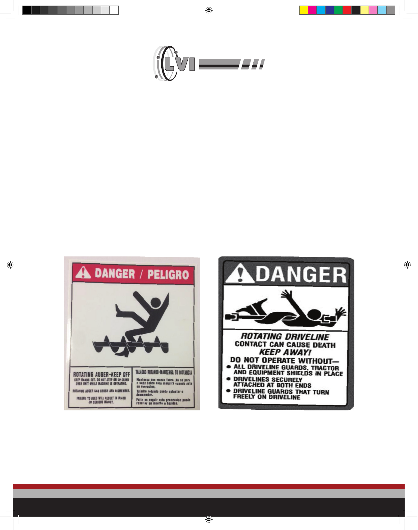
The LVI Pulvimaster is designed to pulverize litter in the poultry house after birds have been taken out of
the house. Please follow these operating suggestions in order to provide maximum eciency of operation
and long life for your machine. Also maintain the machine as suggested.
After attaching the machine to the tractor, verify PTO shaft length is within proper lengths. Adjust tractor
top link so that the Pulvimaster when in the lowered position, the skid shoes are slightly higher in the front
than the rear. This is done to prevent the skid shoes from digging into the poultry house floor.
Adjust the chains on the tail drag lid to allow the lid to move upward to a 45 degree angle while moving
forward. If the chains are adjusted too short the lid will not raise high enough and the pulverized litter will
not be able to exit out the back of the machine. If the pulverized litter cannot exit out the back it will fill
the machine trough and will cause the machine to vibrate and consume more power than necessary. This
situation will vary depending on the depth and moisture of the litter.
Run the tractor PTO at approximately 500 rpm and not greater than 540 rpm. Forward tractor speed
is dependent upon the depth and condition of the litter. At times if the litter has a thick hard crust the
Pulvimaster may need to be run through the litter a second time in order to produce the desired results.
Note: Rocks, stones and other foreign objects can severely damage the machine. Avoid running these
objects into the machine.
MAINTENANCE SCHEDULE
To ensure the long life for which the processor was designed, it is essential that the proper maintenance
procedures are followed. The following chart indicates the manufacturer’s recommended lubrication/
maintenance schedule.
DESCRIPTION HOURS OF OPERATION SPECIAL INSTRUCTIONS
GEAR BOX CHECK EVERY 6 MONTHS 80-90EP GL-5 GEAR OIL
CHAIN CASE CHECK EVERY 3 MONTHS 80-90EP GL-5 GEAR OIL
PTO SHAFT GREASE EVERY 8 HOURS QUALITY LITHIUM 2 GREASE
BEARINGS GREASE EVERY 8 HOURS QUALITY LITHIUM 2 GREASE
Pullvimast_Owners_Manual_2019.indd 9 1/13/20 9:48 AM

10
GEARBOX LUBRICATION
Gearbox: Oil level needs to be up to the small check plug on the side of the gearbox. Oil used is 80-90 EP
gear oil - GL 5 classification. Check oil level on a regular basis. Oil capacity is approximately 3 pints.
DRIVE AND BEARING LUBRICATION
Drive coupler left side of gearbox. Can be accessed from rear of machine underneath drive shaft shield.
Grease 1 pump of grease every 8 hours of use.
(3) Bearings – 2 pumps of grease every 8 hours of use:
1. Upper drive shaft bearing next chain case (not pictured)
2. Rotor bearings lower front edges on left and right end of the machine (see below)
Fill Plug
Check Plug
Pullvimast_Owners_Manual_2019.indd 10 1/13/20 9:48 AM

11
DRIVE CHAIN MAINTENANCE
To check tension adjustment of drive chain. Restrain rotational movement of upper drive shaft. [perhaps
clamp a large vise grip pliers onto the drive shaft] Reach under machine from the rear and grasp the main
rotor by one of the flail bars. While restraining movement of the upper drive shaft, gently rock the main rotor
underneath the machine forward and backward. Notice the distance of movement at the flail attachment
bolt. If the movement is not more than ¾ inch the chain does not need to be adjusted.
If the drive chain needs adjusting proceed as follows. Drain oil out of the chain case by removing oil
level check plug and hoisting up the front of the machine to have oil drain out the plug hole. After oil is
drained out lower front of machine to normal position. Remove nuts and bolts which attach chaincase to
the machine. Drive an appropriate tool or a quality putty knife between the chaincase and the machine
end plate about every 4 inches to cut the sealant loose. Be careful not to bend the chaincase edges. To
adjust chain tension, loosen the 4 bearing retaining bolts. Turn adjusting bolt underneath bearing to push
the bearing and shaft upward. The roller chain should have approximately 1/8” of movement on one span
of roller chain midway between the two sprockets.
Clean the chain case and the machine end plate of all silicone and oil. Put a thin layer of silicone on the
chaincase flange surface. Install the chaincase onto the machine and tighten bolts. Allow silicone to cure
for at least one hour before installing oil into the chain case. Install 80/90 gear oil into chain case up to the
oil check plug. [approximately one pint].
Fill Plug
Check Plug
Pullvimast_Owners_Manual_2019.indd 11 1/13/20 9:48 AM

12
INDEX
3 Pt. Arm .....................................................................................................................................................................................Pg. 14
Front Rubber Curtain ..............................................................................................................................................................Pg. 15
Rotor Assembly ........................................................................................................................................................................Pg. 16
Flails ............................................................................................................................................................................................ Pg. 17
Grease Tube ..............................................................................................................................................................................Pg. 18
Gear Box .....................................................................................................................................................................................Pg. 19
Drive Shaft.................................................................................................................................................................................Pg. 20
Chain Case.................................................................................................................................................................................Pg. 21
Tail Gate Lid ..............................................................................................................................................................................Pg. 22
Drive and Rotor Shaft Bearings..........................................................................................................................................Pg. 23
Top Shaft / Bottom Shaft ......................................................................................................................................................Pg. 24
Drive Chain................................................................................................................................................................................Pg. 25
Skid Shoes ................................................................................................................................................................................Pg. 26
PTO Shaft / Yoke .....................................................................................................................................................................Pg. 27
Ware Plate .................................................................................................................................................................................Pg. 28
Warranty Forms .......................................................................................................................................................................Pg. 29
Pullvimast_Owners_Manual_2019.indd 12 1/13/20 9:48 AM

13
3 PT. ARM
(1) Lower 3 pt. arm attaching pins - #LT873-1887, double pin with nut
(2) Top link pin - #LTFX00076
SERIAL NUMBER PLATE
Right side of upper frame
Pullvimast_Owners_Manual_2019.indd 13 1/13/20 9:48 AM

14
FRONT RUBBER CURTAIN
Pulvimaster 96
95” long x 6’ wide - #LT011619, retained with (10) 3/8” x 1” bolt, nut, lockwasher
Pulvimaster 72
71” long x 6’ wide - #LT050119, retained with (8) 3/8” x 1” bolt, nut, lockwasher
Pullvimast_Owners_Manual_2019.indd 14 1/13/20 9:48 AM

15
ROTOR ASSEMBLY
Rotor assembly with flails installed
#LT082619, Pulvimaster 96
#LT083019, Pulvimaster 72
Pullvimast_Owners_Manual_2019.indd 15 1/13/20 9:48 AM

16
FLAILS
5/8” x 1 3/4” Bolt
5/8” Flat washer
LTPM7-33 Laser washer
LTGB0218 Bushing
LTPM7-30B Flail
5/8” Lock nut
Pulvimaster 96 uses 60 of each item
Pulvimaster 72 uses 44 of each item
BEARING AT EACH END OF ROTOR
1 3/4” I.D. with lock collar
4 bolt mount
#LTB1344
Retained by:
4 - 5/8” x 2” bolt
4 - 5/8” nut
4 - 5/8” lock washer
Pullvimast_Owners_Manual_2019.indd 16 1/13/20 9:48 AM

17
GREASE TUBE
Grease tube on each bearing extends
out front of machine
1 - Grease sert 1/8” NPT #LT63225
1 - Pipe coupler 1/8” NPT #LT228700
1 - Stainless steel tube 1/8” x 8” #LT1XAN4
2 - 45° elbow 1/8” street el #LTSE18B45
Pullvimast_Owners_Manual_2019.indd 17 1/13/20 9:48 AM

18
GEAR BOX #LTB7513
Gear box attachment to frame
4 - 5/8” x 1 1/2” hex head bolt
8 - flat washers
4 - lock washers
Note: flat washers between gear box and main frame
Pullvimast_Owners_Manual_2019.indd 18 1/13/20 9:48 AM

19
DRIVE SHAFT
Top drive shaft gearbox out to chain case
3/8” key way both ends - snap ring groove on one end
1 1/2” diametershaft
Pulvimaster 96 - 35 1/2” long - #LT070119
Pulvimaster 72 - 28” long - #LT070219
DRIVE COUPLER
Drive coupler gearbox to horizontal drive shaft
1 1/2” rnd. I.D. with 3/8” keyway
1 3/8” 6 spline I.D.
#LT080115
Uses 1 - 3/8” key - #LT3838214
Pullvimast_Owners_Manual_2019.indd 19 1/13/20 9:49 AM

20
CHAIN CASE
Chain case assembly - #LT070319
Retained with 12 5/16” x 1” carriage bolt,
nut, lock washer
Breather fitting on top - #LT190729 m91
Breather bushing 3/8” - 1/2” NPT - #LT44236
Oil level check plug 3/8” NPT - #LT44277
HINGES
6 Hinges on rear tail drag lid - #LT660225
4 - 3/8” x 3/4” bolt, nut, lock washer
Rear tail drag lid
Pulvimaster 96 - #LT070419
Pulvimaster 72 - #LT070519
Install with hinge pin “heads” pointed
toward each other
Pullvimast_Owners_Manual_2019.indd 20 1/13/20 9:49 AM
This manual suits for next models
1
Table of contents
Other LVI Farm Equipment manuals