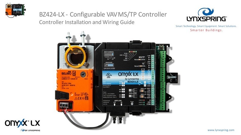
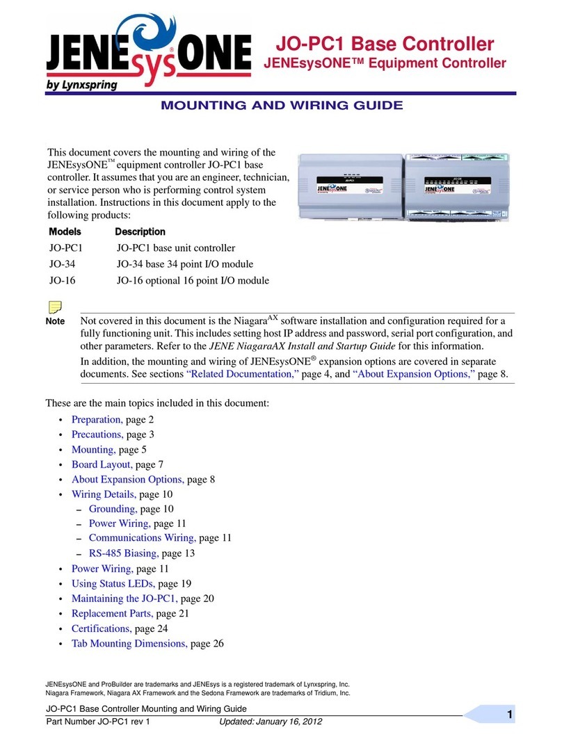
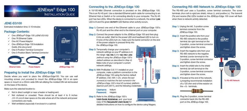
Lynxspring onyxx LX BZ122-LX User manual

BZ122-LX - Configurable VAVMS/TP
Controller Installation and Wiring Guide

BZ122-LX - Configurable VAVMS/TP
Controller Disclaimer Notes
Please read the manual before proceeding to install this controller or any other Onyxx LX device. This manual applies to
Onyxx LX U I software version 4.0 and higher and using
firmware
version
2
.182 and higher.
All firmware updates must be done utilizing Supplied USB-COM adapter or USB to MSTP converter cable.
Installations shall be made by a certified technician and respect all local codes and regulations.
Electronic controls are static sensitive devices: discharge yourself properly before handling and installing a controller.
Any short circuit or incorrect wiring may damage the controller or the controlled equipment.
Double check all wiring before applying power.
If a control failure could lead to personal injury and/or loss of property, it becomes the responsibility of the installer to
add safety devices to protect against failures
www.lynxspring.com

BZ122-LX - Configurable VAVMS/TP
Controller Contents
Disclaimer….................................................................................................................. p. 2
Installation……............................................................................................................. p. 4
Mounting instructions ……………………………….................................. p. 4
Product Label………………………………................................................ p. 5
Wiring Instructions….......................................................................................... p. 7
Jumper Settings….............................................................................................. p. 8
TZ Room Sensor Wiring…….……………………….................................. p. 10
Sequence of Operation ………………………………………………………. p. 11-25
Built-in Application Program Parameters........................................................................ p. 13
Physical Inputs and Outputs................................................................................ p. 26
Analog Values…………………………………………………………. p. 27-30
Binary Values...................................................................................................... p. 31
PID Loops…..…................................................................................................ p. 32
Multi-State Values................................................................................................. p. 33-43
TZxxx Room Sensors........................................................................................... p. 44
RS-485 Network Guidelines….............................................................................................. p. 45-49
Technical Specifications….............................................................................................. p. 50
www.lynxspring.com

Electronic controls are static sensitive devices; discharge yourself properly before manipulating and installing the device.
Short circuits or incorrect wiring may permanently damage the controller. Double check your wiring before applying power.
If acontrol failure could lead to personal injury and/or loss of property, the installer must add safety devices and/or alarm
systems to protect against failures.
Installation
BZ122-LX Mounting Instructions
Failure to properly position the screw will result in torsion and breakage of the unit.
When securing the BZ122 to the
ductwork or sheet metal, make sure that
the rotor shaft bracket is centered, and
the mounting screw is in the center of
the slider. Because the clamp fixes to
the shaft asymmetrically, this allows the
unit to move with the shaft as the
bracket slides back and forth.
www.lynxspring.com

The BZ122-LX consists of an
actuator motor and various screw
terminals, and jumpers, that let you
configure the unit to your needs.
Jumpers are within the housing
(internal), under the removable
cover.Internal labeling inside the
cover helps you identify the
interfaces
Physical connectors (for mounting
and cable connections) are
accessible on the outside of the
unit. This section describes all the
user adjustable interfaces of the
BZ122-LX.Details for each section
are provided further in this guide.
Interface
Product label
www.lynxspring.com

Installation
BZ122-LX Wiring Instructions
Connectors Description
AI1
Common
N/C Inactive input
Common
B-
A+ BACnet MS/TP Comm Bus
24V
Common
B-
A+
TZ Comm Bus
Analog Input
Analog Outputs
AO1
Common
AO2
Binary Outputs
BO1
Common or (BO1,BO2)
BO2
Ground
24VAC
Common Input Power
Mini USB2 Connector Allows local access to the MS/TP network
Requires a Strato Automation USB-485 cable adapter
Cables suitable for use in an RS-485 network should have an impedance of between 100 and 130
ohms, a capacitance between conductors of less than 30 pF per foot (100 pF per meter), and a
capacitance between conductors and shield less than 60 pF per foot (200 pF per meter).
RS-485 Wire Required
Supported Wire Size 28-16 AWG
Wire size based on VA rating and distance from Power source
Supported Wire Size 28-16 AWG
www.lynxspring.com

BACnet MS/TP, TZ Comm Bus, and Power wiring
24VAC Supply
B
A
AI
AO
BO
Cable shield connection (Refer to RS485
network guidelines for proper wiring)
24 VAC
COM
TZ100
B
ABACnet MS/TP
B
ABACnet MS/TP
PO WER B IN ARY OU TPU TS ANA LOG OU T ANALOG INPU T
Tzone
BACnet
MS / TP
The BZ122 is powered using a
Class 2, 24Vac transformer,, do not
ground either side of the
transformer’s secondary
WARNING: Internally, this device utilizes a half-wave rectifier
and therefore can only share the same AC power source with
other half-wave rectified devices. Sharing AC power with full
wave rectified devices is NOT recommended. If not properly
wired, connecting controllers on an MSTP BACnet network
that have internal full wave rectifier controllers with Onyxx LX
half-wave controllers can have adverse effect on network
communications and in some cases would result in damaging
the Onyxx LX Controllers. Not properly wiring the devices will
void the warranty.
For maximum protection from
electrostatic discharge or other
forms of EMI connect each
controller to earth ground using a
#16 AWG and keep these wires as
short as possible.
Proper grounding of a controller is
important to ensure a high probability of
surviving a nearby lightning strike as well as
other possible electrical surges.
For details on
grounding within control
panels, NFPA 79 and
UL508A provide the
required details.
www.lynxspring.com

DIP switches DS2 configures the MS/TP address
The Values of the On Switches adds up
Possible Address : 1 -127
EOL jumper: MS/TP Network end of line
EOL jumper: TZ Bus end of line
Installation
Jumper settings
JP11
JP10
DIP switches DS1 configures the Baud Rate (BPS)
Switches Configuration : Off = 0, On = 1
Available baud rates :
010
-9600 BPS,
110
-19200 BPS,
001
-38400 BPS
, 011
-76800 BPS
These jumpers are used to configure the analog input:
Left = mA 4 -20 mA or 0 –20 mA
Middle = Thermistor 10K Type 3 (std) or Type 2
Right = VDC 0 –10 V or 2 –10 V
www.lynxspring.com

Replaceable TR5R Fuse, Time-Lag type, 2.0 A
Littelfuse 37212000411
Actuator driver connector:
1 = 24V, 2 = A0 , 3 = COM, 4 = Open , 5 = Close
Installation
Jumper settings
External 24VAC supply
Internal 24VAC supply
**recommend using pilot relays in any application utilizing Binary outputs
asswitching loads. **
24V
JP4/
JP5
BO1
COM
BO2 LOAD
LOAD
COM
24Vac
24Vac
JP4/
JP5 LOAD
LOAD
BO1
COM
BO2
24Vac Supply
24Vac
24Vac
www.lynxspring.com

TZ Room Sensor Wiring
•Daisy Chain up to 3 TZ room sensors. All TZroom sensors must be the same model, either all
TZ200 or all TZ100.
•RS-485 Wire Required for communications wiring
•Supported Wire Size 28-16AWG for power wiring, recommend 18 AWG
•Max total distance of communication wire of 300 ft from controller to last TZroom sensor.
•
•
•
•
Field verifyTzone addressing and EOL jumpers
Connect shields together in thedaisy chain communication network(isolatethem to avoid touching
metal or electronic components)
Connectshield toground, at only one extremityof the network
MS/TPA+ and B+ are optional;they are directly connected to the USB connector below theTZxxx.
The goal is to allowaccess to the MSTPnetwork from the special USB to MSTP adapter.
•If there is a loss in communication to any of the TZcontrollers, BV24 will indicate a fault, AV 41 will
=- 40 °F and the fan, heating and cooling will be disabled, and the damper will return to minimum
position.
9
8
7
6
5
4
3
2
1COM
24VAC
N/C
AI
BI
A+
B-
M S/ TP
A+
B-
TZ
DS1
12345678
EOL
TZ100
EOLNONE
JP2
TZ200
COM
24 Vac
A
B
BZxxx
9
8
7
6
5
4
3
2
1
COM
24VAC
N/C
AI
BI
A+
B-
M S/ TP
A+
B-
TZ
DS1
12345678
EOL
TZ100
EOLNONE
JP2
TZ200
9
8
7
6
5
4
3
2
1COM
24VAC
N/C
AI
BI
A+
B-
M S/ TP
A+
B-
TZ
DS1
12345678
EOL
TZ100
EOL
NONE
JP2
TZ200
www.lynxspring.com

Sequence of Operation
Room Temperature
When using TZone sensors, up to three can be configured. The controller can be configured to control the average of all three TZone sensors, a maximum heating call, a maximum
cooling, or individual outputs can be controlled by each TZone sensor, such as separate baseboard heat for particular spaces.
Standard third-party room sensors with push-button override and sliders for set point can be used; however, the room sensor must be a 10K type 2 or 3 with a 5K room setpoint slider
(0-5K = 65°F -85°F)
Occupied Cooling control
During occupied mode and a call for cooling, the damper will modulate open to Max Air Flow setpoint (configurable), maintaining the Occupied Cooling Setpoint (74°F).
Occupied Heating control
During occupied mode and a call for heating, the damper will modulate closed to Min Air Flow setpoint (configurable), maintaining the Occupied Heating Setpoint (72°F).
Outputs can be configured for additional heat, such as Hot Water, Staged Electric, Baseboard, or Modulating Electric Heat (SCR). As the room temperature drops below the heating
setpoint, outputs are cycled on and off to maintain the Heating Setpoint.
When the Downstream T°sensor is configured, the outputs will cycle to maintain a discharge air setpoint of the High Limit Heating (default 95°F) setpoint until the space temperature is
satisfied.
Unoccupied Cooling control
During unoccupied mode and a call for cooling, the damper will modulate open to Max Air Flow setpoint (configurable), maintaining the Unoccupied Cooling Setpoint (80°F).
Unoccupied Heating control
During unoccupied mode and a call for heating, the damper will modulate closed to Min Air Flow setpoint (configurable), maintaining the Unoccupied Heating Setpoint (65°F).
www.lynxspring.com

Sequence of Operation
Standby Cooling control
When a motion sensor is configured on an AI or a TZ200 room sensor is used with a PIR sensor, and motion is not sensed in the space for 60 min (cfg) Cooling will be maintaining the
Cooling Setpoint plus the standby cooling offset.
Standby Heating control
When a motion sensor is configured on an AI or a TZ200 room sensor is used with a PIR sensor, and motion is not sensed in the space for 60 min (cfg) Heating will be maintaining the
Heating Setpoint minus the standby heating offset.
Changeover Mode
*Requires Upstream T°sensor
When the ChangeOver Switching Type [MSV-25] is configured for None, the VAV will remain in cooling mode [MSV-26]. [MSV-26] is writable from BACnet to change mode externally at
priority 9 or higher.
When the Upstream T°sensor is installed, and the ChangeOver Switching Type [MSV-25] is configured for Constant, the VAV will change from heating to cooling mode, regardless of
room temp vs. setpoint, when the supply air from the primary unit is less than 75.2 °F (cfg).
When the Upstream T°sensor is installed, and the ChangeOver Switching Type [MSV-25] is set to RoomT°+Offset, the VAV will change from heating to cooling mode, regardless of room
temp vs. setpoint; when the supply air from the unit is less than Room, the VAV will change from heating to cooling mode, regardless of room temp vs. setpoint, when the supply air from
the unit is less than RoomT°+ Offset value 1°F (cfg).
Demand Limiting
Heating outputs can be limited to reduce energy consumption during peak times. The Aux Output A-E Authorization can be set to MaxPower or Fan+MaxPower. When placed in this
mode, the outputs will be allowed to modulate or cycle from 0-100% (100%). A network variable can modify this setpoint.
Fan Status
The fan status of the primary unit can be used as proof of airflow as status or to prevent outputs from operating when no airflow is detected. Set Aux Output A-E Authorization Fan Status
or Fan+MaxPwr.
www.lynxspring.com

Sequence of Operation
Series Fan Powered Application (as set per MSV-13 Auxiliary output C, control type)
In both occupied & standby mode, the fan is always on.
In Unoccupied mode, the fan will only start when there is a demand for heating or cooling. The fan can be configured with configuration point AuxC Formula to be either on/off or
modulating. If configured on/off, the fan will start when unit is in occupied or standby mode. If configured modulating, the fan will be running at minimum fan speed regardless of
occupancy and as soon as there is a heating or cooling demand (1%+) and will ramp up the fan output. When the heating or cooling demand rises from 30% to 100%, the fan output will
track the heating or cooling demand output. When the heating demand is 0%, the fan will resume minimum fan speed.
Parallel Fan Powered Application (as set per MSV-13 Auxiliary output, control type)
In both occupied, standby & unoccupied modes, the fan will only start when there is a demand for heating. The fan can be configured with configuration point AuxC Formula to be either
on/off or modulating. If configured on/off, the fan will start when there is a call for heat. When the call for heat is satisfied, the fan will stop. If configured modulating, the fan will start as
soon as there is a heating demand (1%+) and will automatically ramp up to 30% fan output. When the heating demand rises from 30% to 100%, the fan output will track the heating
demand output. When the heating demand 0%, the fan will stop.
ECM Minimum Speed (AO)
If modulating fan is chosen, there is an ECM Minimum Speed setting that can be adjusted in Onyxx LX UI below Output C. The default is 30%.
Ramp adjustment boxes below Aux A thru Aux E
Ramp settings are preset to manufacturer recommendations. Adjustments can be performed at user risk and may result in undesirable behavior.
Demand Control Ventilation Application and Sequence (as set per AV66)
If the current CO2 measured reading from the TZ200HC zone sensor exceeds the CO2 setpoint [AV66], the damper will open to the maximum position and the fan will increase to 100% if
using a Modulating Fan or On if Fan is On/Off type.
If the measured reading from the TZ200HC zone sensor reaches within 100ppm greater than the CO2 setpoint [AV66], the fan and damper will modulate toward normal operation in the
BZ controller. Once the measured reading from the TZ200HC zone sensor is less than the CO2 setpoint [AV66], the BZ controller returns to normal operation.
www.lynxspring.com

Sequence of Operation
Maximum Airflow Flow [MaxAFpos] (as set per AV 3)
The maximum airflow flow setting can be set to a value no higher than 4999 CFM. When setting airflow, refer to the box/dampermanufacturer rating for the correct size actuator motor. The
actuator motor that is installed onboard the BZ122 is rated at 45 in-lb.
For assistance in calculating in-lb values you can use this guide from belimo:
https://www.belimo.com/mam/americas/technical_documents/Support%20material/how_to_size_a_damper_actuator.pdf
Minimum Airflow Flow (Heating) [When central system is in cooling] (as set per AV 5)
For boxes that are shut off only, or fan powered (either series or parallel) the heating minimum setting should be the same as the cooling minimum flow setting. Shut off boxes do not
have the capability to heat and should not provide any less air then is required for ventilation. Fan powered boxes will bring in return air to provide the required airflow for proper heating
of the zone. Shut off boxes with reheat should have the heating minimum flow setting set at the level required for proper heating of the zone. This value is typically higher than the
minimum cooling flow setpoint. In normal operation the box will modulate from maximum flow down to minimum cooling flow as there is less call for cooling, then will open to the
heating minimum flow and open the heating coil on a call for heat.
Minimum Airflow Flow (Cooling) [When central systemis in Heating] (as set per AV 6)
The minimum cooling flow should be set based on the ventilation requirements for the zone based on the requirements of ASHRAE 62 or local codes. The minimum flow setting should
be the same regardless if the box is configured as cooling only, cooling with reheat, or fan powered.
zRuntime (assetperAV0)
This setting is used to adjust the run time of the internal airflow actuator only. The default is 95 seconds.
The runtime for any of external BOs are adjustable using Onyxx LX UI only via a Private VAR when applied using a floating output BO1/BO-2 or BO3/BO4. The default is 95 sec.
There is a reference to AV-46 thru 50 but this doesnot write to the Private VAR. Do not write to these AVs in BACnet to adjust the runtime. Adjustment is solely through the
Onyxx LX UI.
www.lynxspring.com

Sequence of Operation Details
RoomT
PidRoomT_Htg
P = 20
I = 0.05
Bias = 0
Reverse
100 PidRoomT_Clg
ActiveRTSP_Clg + 5
P = 20
I = 0.05
Bias = 0
Direct
ActiveRTSP_Htg - 5 ActiveRTSP_Htg ActiveRTSP_Clg
DSsupplyT
PidHL_DST
DSHL_SP - 10 DSH L_SP DSHL_SP + 10
P = 5
I = 0.1
Bias = 50
Reverse
100
50
0
DSsupplyT
PidLL_DST
DSLL_SP DSLL_SP + 10
P = 5
I = 0.1
Bias = 50
Direct
100
0
Temperature
50
DSLL_SP - 10
Tzone2
PidRoomTz2_Htg
P = 20
I = 0.05
Bias = 0
Reverse
100 PidRoomTz2_Clg
ActiveTz2SPClg + 5
P = 20
I = 0.05
Bias = 0
Direct
ActiveTz2SPHtg - 5 ActiveTz2SPHtg ActiveTz2SPClg
Tzone3
PidRoomTz3_Htg
P = 20
I = 0.05
Bias = 0
Reverse
100 PidRoomTz3_Clg
ActiveTz3SPClg + 5
P = 20
I = 0.05
Bias = 0
Direct
ActiveTz3SPHtg - 5 ActiveTz3SPHtg ActiveTz3SPClg
www.lynxspring.com

Sequence of Operation Details
zAirFlow
zPidFlow
zActiveFlowSP zActiveFlowSP +
333,33
P = 0.3
I = 0.01
Bias = 50
Direct
100
0
zActiveFlowSP –
333.33
50
Flow
www.lynxspring.com

Sequence of Operation Details
zPidFlow (%)
49.9
MaxAFpos
(AV3) 100%
zActMod (AO2)
100
0
Cooling
Independent Pressure Control
VAV_Type (MSV27) = 2
MinAFpos
(AV4) 15%
HtgClgMode (MSV26) = 2
(cool)
Contr ol (%)
RoomT_Loc (MSV17):
1x Tzone.
PidRoomT_Clg
2x Tzone.
TzControlMode (MSV34):
Tzone1.
PidRoomT_Clg
Tzone2.
PidRoomTz2_Clg
Average.
(PidRoomT_Clg + PidRoomTz2_Clg) / 2.0
Maximum Htg
MIN(PidRoomT_Clg, PidRoomTz2_Clg)
Maximum Clg
MAX(PidRoomT_Clg, PidRoomTz2_Clg)
3x Tzone.
TzControlMode (MSV34):
Tzone1.
PidRoomT_Clg
Tzone2.
PidRoomTz2_Clg
Tzone3.
PidRoomTz3_Clg
Average.
(PidRoomT_Clg + PidRoomTz2_Clg + PidRoomTz3_Clg) / 3.0
Maximum Htg
MIN(PidRoomT_Clg, PidRoomTz2_Clg, PidRoomTz3_Clg)
Maximum Clg
MAX(PidRoomT_Clg, PidRoomTz2_Clg, PidRoomTz3_Clg)
PidRoomT_Clg On/Off
ON
MinAFpos_Clg
(AV6) 25%
0
MinAFpos
(AV4) 15%
HtgClgMode (MSV26) = 2
(cooling)
AUX mode ON OFF Cooling (A
to E)
PidRoom T_C lg AO
100
MinAFpos_Clg
(AV6) 25%
0
MinAFpos
(AV4) 15%
HtgClgMode (MSV26) = 2
(cooling)
AUX analog Cooling (A to E)
Dependent Pressure Control
VAV_Type (MSV27) = 1
zPidFlow (%)
49.9
MaxAFpos
(AV3) 100
CFM
zActiveFlowSP ( AV2)
100
0
MinAFpos
(AV4) 0
CFM
HtgClgMode (MSV26) = 2
(cool)
PidRoomT_Clg On/Off
MinAFpos_Clg
(AV6) 30 CFM
zActiveFlowSP ( AV2)
0
MinAFpos
(AV4) 0
CFM
HtgClgMode (MSV26) = 2
(cooling)
AUX mode ON OFF Cooling (A
to E)
PidRoomT_Clg AO
100
MinAFpos_Clg
(AV6) 30 CFM
zActiveFlowSP ( AV2)
0
MinAFpos
(AV4) 0
CFM
HtgClgMode (MSV26) = 2
(cooling)
AUX analog Cooling (A to E)
ON
www.lynxspring.com

Sequence of Operation Details
zPidFlow (%)
49.9
MaxAFpos
(AV3)
100%
zActMod (AO2)
100
0
Heating
Independent Pressure Control
VAV_Type (MSV27) = 2
MinAFpos
(AV4) 15%
HtgClgMode (MSV26) = 1
(heat)
Contr ol (%)
RoomT_Loc (MSV17):
1x Tzone.
PidRoom T_Htg
2x Tzone.
TzControlMode (MSV34):
Tzone1.
PidRoom T_Htg
Tzone2.
PidRoomTz2_Htg
Average.
(PidRoomT_Htg + PidRoomTz2_Htg) / 2.0
Maximum Htg
MIN(PidRoomT_Htg, PidRoomTz2_Htg)
Maximum Clg
MAX(PidRoomT_Htg, PidRoomTz2_Htg)
3x Tzone.
TzControlMode (MSV34):
Tzone1.
PidRoom T_Htg
Tzone2.
PidRoomTz2_Htg
Tzone3.
PidRoomTz3_Htg
Average.
(PidRoomT_Htg + PidRoomTz2_Htg + PidRoomTz3_Htg) / 3.0
Maximum Htg
MIN(PidRoomT_Htg, PidRoomTz2_Htg, PidRoomTz3_Htg)
Maximum Clg
MAX(PidRoomT_Htg, PidRoomTz2_Htg, PidRoomTz3_Htg)
PidRoomT_Htg On/Off
ON
MinAFpos_Htg
(AV5) 25%
0
MinAFpos
(AV4) 15%
HtgClgMode (MSV26) = 1
(Heating)
AUX mode ON OFF Heating
(A to E)
PidRoomT_Htg AO
100
MinAFpos_Htg
(AV5) 25%
0
MinAFpos
(AV4) 15%
HtgClgMode (MSV26) = 1
(Heating)
AUX analog Heating (A to E)
Dependent Pressure Control
VAV_Type (MSV27) = 1
zPidFlow (%)
49.9
MaxAFpos
(AV3) 100
CFM
zActiveFlowSP (AV2)
100
0
MinAFpos
(AV4) 0
CFM
HtgClgMode (MSV26) = 1
(heat)
PidRoomT_Htg On/Off
MinAFpos_Htg
(AV5) 30 CFM
0
MinAFpos
(AV4) 0
CFM
PidRoomT_Htg AO
100
MinAFpos_Htg
(AV5) 30 CFM
0
MinAFpos
(AV4) 0
CFM
ON
HtgClgMode (MSV26) = 1
(Heating)
AUX mode ON OFF Heating
(A to E)
HtgClgMode (MSV26) = 1
(Heating)
AUX analog Heating (A to E)
www.lynxspring.com

Sequence of Operation Details
AuxA_Out (AV46)
PidRoomT_Htg (Loop2)
Var1(AuxA_Out)
50%
100
AuxA_Type (MSV5) >=1 && <=4 Heat ing
AuxA_Formula (MSV6) != 4 Analog
AuxA_Auto (MSV7) > 0 Authori ze
AuxA_Auto (MSV7) >= 3
Limited to MaxPower (AV37)
AuxA_Auto (MSV7) = 2 or 4
Limited to PidHL_DST (Loop3)
and FanStatus (BV1).
Var2(AuxA_Out)
70%
0
Aux A Heating AuxA_Out (AV46)
PidRoomT_Htg (Loop2)
Var1(AuxA_Out)
50%
Var2(AuxA_Out)
70%
AuxA_Out (AV46)
PidRoomT_Clg (Loop1)
Var1(AuxA_Out)
50%
100
AuxA_Type (MSV5) >=5 && <=6 Cooling
AuxA_Formula (MSV6) != 4 Analog
AuxA_Auto (MSV7) > 0 Authori ze
AuxA_Auto (MSV7) >= 3
Limited to MaxPower(AV37)
AuxA_Auto (MSV7) = 2 or 4
Lmited to PidLL_DST (Loop4)
and FanStatus (BV1).
Var2(AuxA_Out)
70%
0
Aux A Cooling AuxA_Out (AV46)
PidRoomT_Clg (Loop1)
Var1(AuxA_Out)
50%
Var2(AuxA_Out)
70%
AuxA_Type (MSV5) >=1 && <=4 Heat ing
AuxA_Formula (MSV6) == 4 On/Off
AuxA_Auto (MSV7) > 0 Authori ze
AuxA_Auto (MSV7) >= 3
Limited to MaxPower (AV37)
AuxA_Auto (MSV7) = 2 or 4
Limited to PidHL_DST (Loop3)
and FanStatus (BV1).
AuxA_Type (MSV5) >=5 && <=6 Cooling
AuxA_Formula (MSV6) == 4 On/Off
AuxA_Auto (MSV7) > 0 Authori ze
AuxA_Auto (MSV7) >= 3
Limited to MaxPower(AV37)
AuxA_Auto (MSV7) = 2 or 4
Lmited to PidLL_DST (Loop4)
and FanStatus (BV1).
www.lynxspring.com

Sequence of Operation Details
AuxB_Out (AV47)
PidHtg (%)
Var1(AuxB_Out)
65%
100
AuxB_Type (MSV9) >=1 && <=4 Heat ing
AuxB_Formula (MSV10) != 4 Analog
AuxB_Auto (MSV11) > 0 Authori ze
AuxB_Auto (MSV11) >= 3
Limited to MaxPower (AV37)
AuxB_Auto (MSV11) = 2 or 4
Limited to PidHL_DST (Loop3)
and FanStatus (BV1).
Var2(AuxB_Out)
85%
0
Aux B Heating
AuxB_Out (AV47)
PidHtg (%)
Var1(AuxB_Out)
65%
Var2(AuxB_Out)
85%
AuxB_Out (AV47)
PidClg
Var1(AuxB_Out)
65%
100
AuxB_Type (MSV9) >=5 && <=6 Cooling
AuxB_Formula (MSV10) != 4 Analog
AuxB_Auto (MSV11) > 0 Authori ze
AuxB_Auto (MSV11) >= 3
Limited to MaxPower(AV37)
AuxB_Auto (MSV11) = 2 or 4
Lmited to PidLL_DST (Loop4)
and FanStatus (BV1).
Var2(AuxB_Out)
85%
0
Aux B Cooling
AuxB_Out (AV47)
PidClg
Var1(AuxB_Out)
65%
Var2(AuxB_Out)
85%
AuxB_Type (MSV9) >=1 && <=4 Heat ing
AuxB_Formula (MSV10) == 4 On/Off
AuxB_Auto (MSV11) > 0 Authori ze
AuxB_Auto (MSV11) >= 3
Limited to MaxPower (AV37)
AuxB_Auto (MSV11) = 2 or 4
Limited to PidHL_DST (Loop3)
and FanStatus (BV1).
AuxB_Type (MSV9) >=5 && <=6 Cooling
AuxB_Formula (MSV10) == 4 On/Off
AuxB_Auto (MSV11) > 0 Authori ze
AuxB_Auto (MSV11) >= 3
Limited to MaxPower(AV37)
AuxB_Auto (MSV11) = 2 or 4
Lmited to PidLL_DST (Loop4)
and FanStatus (BV1).
PidHtg (%)
RoomT_Loc (MSV17):
1x Tzone.
PidRoom T_Htg
2x Tzone.
TzControlMode (MSV34):
Tzone1.
PidRoom T_Htg
Tzone2.
PidRoomTz2_Htg
Average.
(PidRoomT_Htg + PidRoomTz2_Htg) / 2.0
Maximum Htg
MIN(PidRoomT_Htg, PidRoomTz2_Htg)
Maximum Clg
MAX(PidRoomT_Htg, PidRoomTz2_Htg)
3x Tzone.
TzControlMode (MSV34):
Tzone1.
PidRoom T_Htg
Tzone2.
PidRoomTz2_Htg
Tzone3.
PidRoomTz3_Htg
Average.
(PidRoomT_Htg + PidRoomTz2_Htg + PidRoomTz3_Htg) / 3.0
Maximum Htg
MIN(PidRoomT_Htg, PidRoomTz2_Htg, PidRoomTz3_Htg)
Maximum Clg
MAX(PidRoomT_Htg, PidRoomTz2_Htg, PidRoomTz3_Htg)
PidClg (%)
RoomT_Loc (MSV17):
1x Tzone.
PidRoomT_Clg
2x Tzone.
TzControlMode (MSV34):
Tzone1.
PidRoomT_Clg
Tzone2.
PidRoomTz2_Clg
Average.
(PidRoomT_Clg + PidRoomTz2_Clg) / 2.0
Maximum Htg
MIN(PidRoomT_Clg, PidRoomTz2_Clg)
Maximum Clg
MAX(PidRoomT_Clg, PidRoomTz2_Clg)
3x Tzone.
TzControlMode (MSV34):
Tzone1.
PidRoomT_Clg
Tzone2.
PidRoomTz2_Clg
Tzone3.
PidRoomTz3_Clg
Average.
(PidRoomT_Clg + PidRoomTz2_Clg + PidRoomTz3_Clg) / 3.0
Maximum Htg
MIN(PidRoomT_Clg, PidRoomTz2_Clg, PidRoomTz3_Clg)
Maximum Clg
MAX(PidRoomT_Clg, PidRoomTz2_Clg, PidRoomTz3_Clg)
www.lynxspring.com
Table of contents
Other Lynxspring Controllers manuals

Lynxspring
Lynxspring JENEsys Edge 534 User manual

Lynxspring
Lynxspring BW437-FCU-LX User manual

Lynxspring
Lynxspring JENEsys Edge 414 User manual

Lynxspring
Lynxspring JENEsys Edge 534 User manual

Lynxspring
Lynxspring JENEsysONE JO-PC1 Installation instructions manual

Lynxspring
Lynxspring onyxx LX BW437-RTU-LX User manual

Lynxspring
Lynxspring JENEsys Edge 100 User manual

Lynxspring
Lynxspring ONYXX LX BZ424-LX User manual
Lynxspring
Lynxspring JENEsys Edge 534 User manual