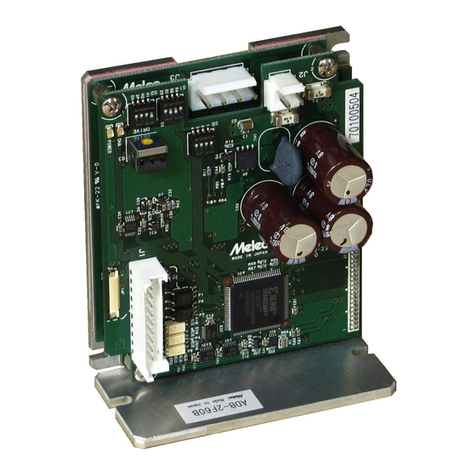
M-Elec C-VX875 User manual

Stepping & Servo Motor Controller
C-VX875
Instructions Manual
(For designers' use)
MN0203
Please ensure to read and understand this
Instructions Manual before using the Product.
Please keep this Instructions Manual at hand
so that it is always available for reference.

-2-
Introduction
This instructions manual explains the handling of "Stepping Motor and Servo Motor Controller C‑VX875"
emphasizing the specifications to enable proper and safe use.
The manual is thus intended for designers of control systems using stepping motors or servo motors.
Before using the product, read this manual carefully for better understanding.
Keep the manual handy so that you can read it whenever you want.
Wish and Notes
■The product and product specification which are indicated in this manual may be changed without a
preliminary announcement by improvement etc.
■The technical information indicated in this manual is for explaining typical operation and
application of a product, and does not perform consent of the guarantee to the intellectual
property rights and other rights of our company and a third party, or an actual right on the
occasion of the use.
■When you use the circuit indicated in this manual, software, and the information relevant to these,
please fully evaluate by a user's whole apparatus and system.
Moreover, please judge application propriety on a user's responsibility.
■The product which uses a semiconductor and a semiconductor may malfunction depending on an operating
condition, or a certain probability.
In order not to generate an accident resulting in injury or death, a fire accident, social damage,
etc. by failure or malfunction of this product, please cope with a safety design required for the
last equipment or a system, according to a user's responsibility.
■This product is designed and manufactured as a general industrial‑oriented general‑purpose product.
Therefore, please do not use aircraft instruments, an aerospace instrument, a submarine relay
appliance, a nuclear control system, transport plane machines (vehicles, a vessel, etc.), the signal
machine for traffic, disaster prevention / crime prevention apparatus, a safeguard, medical equipment,
etc. for the use which can consider big influence by a human life or property.
■Do not carry out reconstruction, change, and reproduction of this product.
■Please observe export related statutes applied, such as "foreign exchange and Foreign Trade Law",
when exporting, and perform required procedure by the place provided by this statute.
Please do not use the technical information indicated in this product or this manual for the purposes,
such as development of mass‑destruction weapons, the purpose of military use, and the other purpose
of a military use.
Moreover, this product cannot be used for the apparatus to which manufacture, use, and sale are
forbidden by a statute in and outside the country and regulation.
■Please be sure to ask to window of our marketing department about details, such as the environmental
suitability of this product.
■When using it, content of a specific substance, RoHS Directive which regulates use, etc. should
investigate the environmental related statute applied enough. And please suit this statute.
About the damage which arose by not observing the statute which requires to user, our company does
not take any responsibility.
C-VX875
Instructions Manual

-3-
Description of Safety
This product must be handled correctly.
Handling the product incorrectly may cause unexpected accidents resulting in personal injuries or
damage to your properties.
Many of those accidents can be avoided if you have advance information on dangerous situations.
This manual provides precautions where dangerous situations are predicted. The manual provides the
following alert marking and messages for this purpose:
This indicates a hazardous situation that could result in death or serious
WARNING
personal injury if you do not perform the procedure correctly.
This indicates a potentially hazardous situation that could result in personal
CAUTIONinjury or physical damage if you do not perform the procedure correctly.
Before Use
■Set up the product before operating it.
Refer to Section 3, "Setting."
■This product is equipped with a LIMIT (overtravel) signal and an FSSTOP signal to prevent mechanical
damage.
The initial values of these signals are set to ACTIVE OFF (B contact). Accordingly, even in a
system configuration in which the FSSTOP and LIMIT signals are not used, pulses are not output
unless NORMAL ON (GND connection) is enabled.
■The C‑VX875 allows axes to be controlled independently and therefore referred to each axis
as follows:
1st axis 2nd axis 3rd axis 4th axis
X axis Y axis Z axis A axis
・AL‑Ⅱ I/O communication of C‑VX875 explains C‑VX875 as a master board.
・This manual basically explains only the X axis.
■Please also read the device driver operation manual for Windows which suited this product.
C-VX875
Instructions Manual

-4-
C-VX875
Instructions Manual
Introduction
Wish and Notes
Description of Safety
Before Use Contents PAGE
1.OVERVIEW
1‑1. Features 5
1‑2. Product Configuration 5
1‑3. Example of System Configuration 5
1‑4. Function Block Diagram 6
1‑5. Externals of product 8
2.SPECIFICATIONS
2‑1. General Specifications 9
2‑2. PCI Specifications 9
2‑3. Basic Specifications 10
2‑4. Applied Functions 12
2‑5. AL‑Ⅱ I/O Communication specifications 14
2‑6. Input and Output Signal Table 15
(1) User I/O connector (J1) 15
(2) AL‑Ⅱ I/O communication connector (J2) 17
(3) Special‑purpose I/O connector (J3) 18
2‑7. Input and Output Specifications 19
(1) Output specifications 19
(2) Input specifications 20
2‑8. Outside Dimensions 21
3.SETTING
3‑1. Installation of device driver for Windows 22
3‑2. Setting the Board Number(S1) 22
3‑3. Setting of the AL‑Ⅱ I/O communication 22
(1) Address setting of the AL‑Ⅱ I/O seiries 22
(2) Baud rate setting of the AL‑Ⅱ I/O seiries 22
(3) Retry number setting of the AL‑Ⅱ I/O seiries 22
3‑4. Setting of Extend communications 22
4.CONNECTION
4‑1. Example of user I/O Interface Power Supply Connection 23
4‑2. Examples of Connection to Drivers 24
(1) Example of connection to the stepping motor driver 24
(2) Example of connection to the servo motor driver 25
4‑3. Examples of Connection to Sensors 26
(1) Example of sensor attachment (photosensor) 26
(2) Example of connection to a limit sensor 26
(3) Example of connection to an origin sensor 27
4‑4. Connection to AL‑Ⅱ communication system 29
(1) Core connection of AL‑Ⅱ I/O communications cable 29
(2) Connection of terminator 29
(3) Wiring distance of AL‑Ⅱ I/O communications 29
(4) Power supply and slave power for communication 29
5.Maintenance
5‑1. Maintenance and Inspection 30
(1) Cleaning method 30
(2) Inspection method 30
(3) Replacement method 30
5‑2. Saving and Disposal 30
(1) Saving method 30
(2) Disposal method 30
The main parts which revised by this manual

-5-
C-VX875
Instructions Manual
1.OVERVIEW
1‑1. Features
● The C‑VX875 is controller equipped with four independently functioning axes.
This controller supports servo and stepping motors that can directly be inserted into slots of a PCI
bus system conforming to PCI bus specifications R2.2.
・From RJ‑45 connector of a front panel, a maximum of four slave I/O units of AL‑Ⅱ series are
connectable by AL‑Ⅱ I/O communication.
Moreover, an Extended I/O unit can also be extended to a slave I/O unit.
Thereby, 4 axes motor control and the I/O system of a maximum of 256 points/256 points can be
built by one PCI slot.
・The board shape is the universal short card size (107 x 170) of the PCI bus standard.
● The C‑VX875 is equipped with our chip controller MCC07 to enable motor control using simple commands.
・C‑VX875 enables four independently linear interpolation driving, 2‑axis linear interpolation
(fixed interpolation‑axes) or 2‑axis circular interpolation (fixed interpolation‑axes) driving.
Moreover,the C‑VX875 is enable to optional axes liner interpolation drive or Optional 2‑axis
(Applied function)circular interpolation drive.
・The 32‑bit width address counter and the maximum output frequency of 6.5 MHz of the MCC07 enables
high‑precision, high‑speed positioning.
・Also equipped with a multi‑functional 32‑bit pulse counter, and 16‑bit pulse differential counter,
the C‑VX875 has a variety of application such as counting feedback pulses from the servo driver,
detecting step‑out of the stepping motor with an encoder. The applications also include interrupt
output and external signal output using the comparator function of each counter.
・After the command being executed is finished, the commands stored in the reservation register are
(Applied function)executed sequentially. Then this function can be allowed continuous drive.
1‑2. Product Configuration
Product name Rating Maker Quantity Remarks
Controller C‑VX875 Melec Inc. 1 (Main unit)
1‑3. Example of System Configuration
C‑VX875 Option Stepping ervo
PC or S
Cable Relay unit Driver otorM
X‑axis
CB‑25A/4C etc.
・CE‑33‑E4/100A10 (1m) Y‑axis
・CE‑34‑E4/100A20 (2m)
(Direct installation) ・CE‑35‑E4/100A30 (3m)
・CE‑36‑E4/100A50 (5m) Z‑axis
Option
Device driver
AL‑Ⅱ I/O communication A‑axis●MPL‑30‑01vx.xx/PCIW32 *1
30m/20Mbps,50m/10Mbps・Windows 2000
ORG, LIMIT sensor, Encoder signal etc.・Windows XP(32 Bit)
2CB‑01v1/3232‑MIL etc.・Windows Vista(32 BIt)
・Windows 7(32 Bit)
I/O 32/32 points
CB‑52/3232‑MIL etc.
●MPL‑31‑01vx.xx/PCIW64 *1
・Windows XP(64 Bit)
I/O 32/32 points・Windows Vista(64 Bit)
2CB‑02v1/1616‑MIL etc.・Windows 7(64 Bit)
I/O 16/16 points
*1 Please check the latest version number of vx.xx by the operation manual of device driver.
C-VX875
PL4
PL3
PL2
PL1
JP1
IN
J6
OUT
J5
J2J1
MADEIN JAPAN DC+24V
J3
J4
OUT INJ7 J8
J1 J2
J3 J4
J6J5
DC+24V
IN
OUT
INOUT
MADE IN JAPAN
J4 J3DC+24V
MADE IN JAPAN
J1 J2
J5 OUT J6 IN

-6-
C-VX875
Instructions Manual
1‑4. Function Block Diagram
CN1 J1
Drive Control block
Driver & Sensor
X‑axis Counter block
Drive Control block
Driver & Sensor
Y‑axis Counter block
Drive Control block
Driver & Sensor
Z‑axis Counter block
PCI Bus Local Bus Drive Control block
Driver &Sensor
A‑axis Counter block
General‑purpose output
(OUT0‑‑OUT3) General‑purposeI/O
General‑purpose input
(IN0‑‑IN3) SENSORx Input
J3
Hard Configuration block
Manual Input
(Applied Function) SIGNAL INx Input
SIGNAL OUTx Output
(Applied Function)
J2
(Insulation)
A
L
‑
AL‑Ⅱ I/O Communication
Ⅱ
Control block I
/
O
Bus interface block
Interface block with the PCI bus
Drive control block
The drive control block outputs serial pulses to the motor driver.
The 2‑axis indicated by is interrelation.
It enables 2‑axis linear interpolation or 2‑axis circular interpolation.
Counter block
The counter block has three types of counters: ADDRESS COUNTER, PULSE COUNTER, and DFL COUNTER.
(Can use as hard timer.)
ADDRESS COUNTER, PULSE COUNTER has 32‑bit counter, DFL COUNTER has 16‑bit counter.
These counters count pulses output by the controller or signals such as feedback signals from the
encoder.
Each counter equipped with three compare registers. These registers count optional count.
General‑purpose OUTPUT block
The block can control OUT0〜OUT3
General‑purpose INPUT block
The block can control IN0〜IN3
M
C
C
0
7
M
C
C
0
7
B
u
s
i
n
t
e
r
f
a
c
e
b
l
o
c
k
U
s
e
r
I
/
O
S
P
E
C
I
A
L
‑
P
U
R
P
O
S
E
I
/
O
A
L
Ⅱ
I
/
O
U
N
I
T

-7-
C-VX875
Instructions Manual
Hard Configuration block (Applied Function)
The Hard Configuration block is a control block that allows the user to connect User I/O and
Special‑purpose I/O to signals: Multipurpose sensor signal input to each axis, signal for
synchronization control, status signal.
The control block is used for multipurpose sensor function, Synchronous drive function, Status
output function.
User I/O block
The user I/O block interfaces with motor drivers, sensors, and general‑purpose I/O equipment
signals.
Special‑purpose I/O block (Applied Function)
The block interfaces with input signals what motors can be operated manually, and what can output
status signals to the outside.
AL‑Ⅱ I/O Communication Control block
It is the circuit block which controls AL‑Ⅱ I/O communication.
The interface part of AL‑Ⅱ I/O communication is insulated with C‑VX875 internal circuit
(personal computer power supply).
AL‑Ⅱ I/O Communication interface block
They are a slave I/O unit of AL‑Ⅱ series, and an interface part which performs AL‑Ⅱ I/O
communication.

-8-
C-VX875
Instructions Manual
1‑5. Externals of product
CN1 Universal (5V/3.3V) board edge connector inserted into a PCI bus.
J1 100‑pin half pitch connector that interfaces the motor driver, sensor signals, and
equipment having +24V interface I/O.
Dedicated interface cables (1m, 2m, 3m, and 5m) and relay units are available.
J2 This is a RJ‑45 type shield connector which connects AL I/O communication.
The slave I/O unit of AL‑Ⅱ series is connectable with AL‑Ⅱ I/O communication.
J3 Connector that interfaces with external signals at TTL level.
Motors can be operated by manual operation through this connector.(APPLIED FUNCTION)
External input signals can be assigned as input signals to signals for the SENSOR and
signal for synchronization control.
Signals can be output to the outside by status signal of each axis.
A general‑purpose standard MIL connector is used.
S1 Rotary switch that is set so that PCI can recognize the board number.
If two or more boards are inserted into the PC simultaneously, set the switch properly
so that every board number is unique.
RDY LED LEDs that allows the user to simply monitor the X, Y, Z, and A axes to check whether
the axes are operating normally. The RDY LED corresponding to each axis is on while
the axis is waiting for a command and is off during command processing.
PL5,PL6 These are LED for a monitor of AL‑Ⅱ I/O communication.
・PL5(Red) … This LED emits light, when the abnormalities or hard abnormalities of
AL‑Ⅱ I/O communication are detected.
・PL6(Green) … This LED emits light, when it can access from a PCI bus.
・PL7,PL8 … It is not used.
JP1 It is a connector for adjustment. Nothing should connect.
CN2 It is not used now. It is a connector for extension.
Nothing should connect.
CN2
C-VX875
PL8
PL7
PL6
PL5
1JP1
MADE IN JAPAN

-9-
C-VX875
Instructions Manual
2.SPECIFICATIONS
2‑1. General Specifications
No. Item Specifications
1 Supply voltage, ・+5V ±5%, 1.0 A or less
power consumption ・+24Vdc ±2V, 200 mA or less (for photocoupler interface)
2 Operating ambient ・0℃ 〜 +45℃
temperature and ・80%RH or less (without dew condensation)
humidity
3 Storage ・0℃ 〜 +55℃
temperature and ・80%RH or less (without dew condensation)
humidity
4 Installation ・Inside a well‑ventilated cabinet installed indoor, free from direct sunlight
environment ・Not exposed to corrosive and flammable gasses, and not affected by oil mist,
dust,salt, iron powder, water, and chemicals
・Not subject to constant vibration or excessive shock
・Not affected by electromagnetic noise caused by power equipment
・Free of radioactive materials and magnetic fields, and not in vacuum
5 Dimensions ・Short card size (107mm×170mm×17mm)
6 Weight ・About 0.2 kg
2‑2. PCI Specifications
No. Item Specifications
1 Applicable PCI Local Bus Specification Rev2.2
standard
2 Bus interface ・32‑bit bus, 33 MHz clock
・5V/3.3V Signal system (Universal)
※ It is nesessary +5V power supplied from the bus slot.
3 Interrupt ・INTA#
However, there is no interrupt from AL‑Ⅱ I/O communication.
4 System Resouce ・I/O : 128‑byte + 256‑byte

-10-
C-VX875
Instructions Manual
2‑3. Basic Specifications
No. Item Specifications
1 Number of 4 axes
control axes
2 Pulse output Output type ・Independent direction output/Specified direction output/
function Phase‑differential signal output
・Line driver output
Output frequency ・Independent drive :0.1 Hz to 6.5 MHz
・Interpolation drive:0.1 Hz to 5 MHz
5000 ms/kHz to 0.0025 ms/kHz (Trapezoid/S‑curve)Acceleration/deceleration
time constant
Trapezoid/S‑curve(This feature enables to set asymmetricalAcceleration/deceleration
shape shape)
Triangular drive ・During S‑shaped acceleration/deceleration drive, INDEX
prevention function drive may end before the maximum speed is reached.
In this event, triangular drive can be automatically
avoided.
Number of output pulses ・JOG drive : ‑65,535 to +65,535 pulse
・SCAN drive : Up to infinite pulses
・INDEX drive : ‑2,147,483,647 to + 2,147,483,647 pulses
3 Encoder Input type ・Incremental
function ・Line receiver input
Input range ・〜5MHz
External signal output ・External signals such as hand pulser signals that are input
to the EA and EB signals can be output as CWP and CCWP
signals.
4 Drive JOG drive ・Pulses are constantly output until the specified pulses.
・Pulses are continuously output until a stop command is detected.function SCAN drive
INDEX drive ・Pulses are output until the specified relative or absolute
address is reached.
ORIGIN drive ・The specified drive processes are performed.
This drive is finished when the ORG signal specified edge
is detected.
2‑axis linear ・Linear interpolation is performed toward the specified
interpolation drive coordinates from the current coordinates.
・Driving type is selected from INDEX drive or SCAN drive.
・Max speed is 5MHz.
・Positional errors for the specified straight line are
±0.5 LSB.
・The absolute and relative addresses that can be specified
for coordinates range from ‑2,147,483,647 to +2,147,483,647
(32 bits).
2‑axis circular ・Circular interpolation is performed toward the specified
interpolation drive coordinates from the current coordinates on the circular
curve specified by the center‑point or passing‑point
coordinates.
・Driving type is selected from INDEX drive or SCAN drive.
・Max speed is 5MHz.
・Positional errors for the specified circuit curve are ±1
LSB.
・The relative addresses range from ‑8,388,607 to +8,388,607
(24 bits).
・Short axis pulses range from
‑2,147,483,648 to +2,147,483,647 (32 bits).
Linear speed constant ・Control is performed to keep the synthesized speed of the
control two axes working for interpolation drive constant.

-11-
C-VX875
Instructions Manual
No. Item Specifications
5 Stop Slow stop function ・SLOW STOP command
function ・Detection of a match of the comparator of each counter.
・IN0‑‑IN3 signal setting the DALM input function, the DALM
signal can be used as the slow stop signal.
・Multipurpose sensor signal(SS0,SS1)
Immediate stop function ・FAST STOP command
・FSSTOP singal (User I/O)
・FSSTOP signal (Special‑purpose I/O)
・Detection of a match of the comparator of each counter.
・IN0‑‑IN3 signal setting the DALM input function, the DALM
signal can be used as the immdiate stop signal.
・Multipurpose sensor signal(SS0,SS1)
LIMIT signal ● direction stop+
・Immediate stop by CWLM signal and slow stop can be selected.
・Slow stop or immediate stop can be performed for each axis
upon detection of a match of the comparator(COMP2) of each
counter.
● direction stop
‑
・Immediate stop by CCWLM signal and slow stop can be
selected.
・Slow stop or immediate stop can be performed for each axis
upon detection of a match of the comparator(COMP3) of each
counter.
6 Counter Address counter ・32‑bit counter that manages absolute addresses by counting
function drive output pulses.
Pulse counter ・32‑bit counter that countes external pulse signals or
encoder feedback pulses.
Pulse differential ・16‑bit counter that detects differences in the number of
counter pulses by counting external pulse signals and encoder
feedback pulses.
・It can also be used as a 16‑bit timer.
Comparator function ・Detection of a match of the three comparators of each
counter.
・Upon detection of a match by the comparator, pulse output
can be decelerated and then stopped, or stopped immediately.
・Upon detection of a match by the comparator, output external
status signal.
AUTO CLEAR function ・The comparator of each counter:The counter can automatically
be cleared upon detection of a match of COMP1 of each
counter.
AUTO ADD function ・The comparator of each counter:If the couter value reaches
the COMP1, a value that is set by the data add to COMPARE
REGISITER1.
7 Other Servo driver support ・The signals are specially prepared as servo driver suport
functions function signals.
・Servo positioning completion input/phase (DEND/PO)
signal input
・Servo reset output (DRST)
・General‑purpose input signal(DALM .etc) (IN0‑‑IN3)
・General‑purpose output signal(S.ON .etc) (OUT0‑‑OUT3)
Data reading function ・Current status information can be read in real time.
Current status information includes status data, count data
of a counter etc.

-12-
C-VX875
Instructions Manual
2‑4. Applied Functions
No. Item Description of specifications
1 Drive UP/DOWN/CONST drive CHANGE ・Drive change for acceleration, deceleration, or
function function constant speed can be performed upon detection of
signal at an arbitrary change operation point.
SPEED CHANGE function ・The drive pulse speed is changed upon detection of
signal at an arbitrary change operation point.
RATE CHANGE function ・The rate is changed upon detection of signal at
an arbitrary change to the specified rate.
INDEX CHANGE function ・Upon detection of signal at an arbitrary change
operation point, the stop position at which drive
is to be finished is changed.
・Upon detection of the INC INDEX CHANGE command, the
system performs INC INDEX drive by setting the
specified data at the stop position of the relative
address for which the start position is the origin.
・Upon detection of the ABS INDEX CHANGE command, the
system performs ABS INDEX drive by setting the
specified data at the stop position of the absolute
address managed with the address counter.
Optional axes liner ・Linear interpolation is performed toward the
interpolation drive specified coordinates from the current coordinates.
Then long axis outputs pulses.
Optional 2‑axis circular ・Circular interpolation is performed toward the
interpolation drive specified coordinates from the current coordinates
on the circular curve.
INDEX drive controll ・This function is allowed to set OFFSET of the start
the start point at auto point at auto deceleration. This function can be used
deceleration When INDEX drive,liner interpolation INDEX drive,
and circular interpolation INDEX drive.
MANUAL SCAN drive ・MANUAL SCAN/JOG drive in the + or ‑ direction is
performed by operation of SELA to D,MAN, CWMS, CCWMS
signal input through the J3 connector.
2 Count function Ring counter function ・The address counter, pulse counter each are a ring
counter in which any maximum count can be set.
Count data latch/clearance ・This function latches count data of a counter ata
function specific latch timing and holds it till the next latch
timing.
・Each counter can latch counter value at arbitrary
timing. It is possible to clear a counter value at the
latch timing.
3 Other Interrupt function ・Each axis can output interrupt signals to the CPU.
functions ・Each interrupt signal is output when an interrupt is
caused by drive end, state of a reservation register,
and detection of a match by the counter.
Command reservation ・Each axis has a reservation register that can store
function data commands for ten instructions.
・General‑purpose commands of Drive commands can be
reserved in the reservation register.
・After the command being executed is finished, the
commands stored in the reservation register are
executed sequentially.Then this function can be
allowed continuous drive.

-13-
C-VX875
Instructions Manual
No. Item Description of specifications
3 Other Input signal logical switch ・The input signal can be changed to logic as follows:
functions function ・CWLM
・CCWLM
・DALM (INx is used for DALM function)
Input signal time constant ・The input signal can be set time constant as follows:
function ・CWLM
・CCWLM
・DALM (INx is used for DALM function)
・DEND/PO
・ORG
・NORG
・±ZORG
・±EA,EB
Multipurpose sensor Each axis has multipurpose sensor signal input used as
signal input stop signal, trigger signal of a counter latch data
and drive CHANGE operating signal.
The signal can be used as multipurpose sensor as
follows:
・SENSORx input signal
・SIGNAL INx input signal
・A status in any axis
Status external signal ・The compare register value, STATUS, output signal
output function of each counter can output as SIGNAL OUTx output
signal.
Synchronized start ・You can perform synchronized start with any axis.
function ・A condition of start can be set by the condition as
follows:
・SENSORx input signal
・SIGNAL INx input signal
・A status in any axis
・PAUSE command
Status read ・Current status information can be read in real time.
Data reading ・Current status information includes setting data
any axis, latch data of a counter etc.
※ Applied function.
Refer to the separate manual of the Windows device driver corresponding to C‑VX875 Applied Functions
Part.

-14-
C-VX875
Instructions Manual
2‑5. AL‑Ⅱ I/O Communication specifications
No. Item Description of specifications
1 AL‑Ⅱ I/O Conformity standard RS485 (Insulation type)
interface Transmission protocol Protocol for AL‑Ⅱ I/O communication
Application slave ・2CB‑01v1/3232‑MIL (32/32 points)
・2CB‑02v1/1616‑MIL (16/16 points)
Slave connection number A maximum of 4 slave
・C‑VX875 address of AL‑Ⅱ I/O communication
: H'0 fixation
・Slave address setting range
: Within the limits of H' 1〜H' F
Wiring distance/baud rate ・50 m/10 Mbps
・30 m/20 Mbps
2 Reading of slave The slave type connected now can be read.Connected
informationconfirmation
of slave
3 Reading of error total ・The error total number detected in the AL‑Ⅱ I/OError detection
number communication after the power supply is turned onof AL‑Ⅱ I/O
can be read.communication
・It is possible to use it for the evaluation of the
communication environment.
・When retrying is detected, it counts as an error.
・The error total number can be counted 65535 times
or less. More than it do not update a count.
Clear of error total number The value in which the error total number is counted can
be cleared to 0.
Retry ・It is a function to evade the stagnation of the entire
system by retrying it when the influence of the noise
etc. is given to AL‑Ⅱ I/O communications.
・The number of retrying is set by an Environment‑set‑
function.
When retrying is made effective and the communication
abnormality is detected, retrying is automatically
executed.
・The setting of retrying is possible by the range from
0 (non‑retry) to 3.
4 Initialize Auto transmission of The master carries out initialization for all slaves
initialization automatically when user carries out an Environment‑set‑
function to a master.
Interlock ・When an Environment‑set‑function is executed from the
application, master executes initialization
(a request) to each slave.
・The slave product of the AL‑Ⅱ series doesn't accept
other requests until the initial‑request sent from
master is received after the power supply is turned
on.
・When other requests are received, an initial error is
returned. As a result, master notifies the application
the answer back.
・When the internal logic on the slave side was reset by
the power failure etc. momentarily, operation by the
improper data can be stopped.
Please execute to master an Environment‑set‑function,
after turning on slave's power supply.
* Refer to the operation manual of 2CB‑01v1/3232‑MIL or 2CB‑02v1/1616‑MIL, about the slave I/O unit
specification of AL‑Ⅱ I/O communication connectable with C‑VX875.

-15-
C-VX875
Instructions Manual
2‑6. Input and Output Signal Table
(1) User I/O connector (J1)
■Pin assignments
(J1)
・Connector type name :HDRA‑E100LFDT‑SL+ (HONDA TSUSHIN KOGYO)
・Adaptable socket :HDRA‑E100MA1+ ,HDRA‑E100M1+ etc.
(HONDA TSUSHIN KOGYO, not included in attached accessories)
(Adaptable socket is 100‑pin)
・Adaptable cable :CE‑33‑E4/100A10 (1 m in length)
CE‑34‑E4/100A20 (2 m in length)
CE‑35/E4‑100A30 (3 m in length)
CE‑36/E4‑100A50 (5 m in length)
* The above‑mentioned conformity cables are not accessories.
Although C‑VX875 is a 4 axis controller, the suiting cable becomes
"8 axes and 12 axis controllers." Reference
For more information about a cable preparing in the
C‑VX870 series, refer to the instruction manual of
"The connecting cable for board controllers" .
■Signal table
This product may be damaged.
CAUTION Do not connect +24V to any pin other than EXTV.
After wiring, be sure to confirm the wiring before power‑on.
● A signal indicated by is photocoupler‑insulated.
● A signal is enable to set time constants marked with ☆.(Applied function)
● Logic switching is enabled for an input signal marked with ★.(Applied function)
Logic switching is enabled for general‑purpose input signal INx,
when this signal is used for DALM function
(Note 1)
An external power supply is required for a signal that is photocoupler‑insulated.
The specified input voltage range is +24V ±2V.
Current consumption at +24V is up to 200mA.
The initial values of the CWLM and CCWLM signals of each axis and the FSSTOP signal are
ACTIVE OFF input (B contact).
An external power supply must be connected even if these signals are not used.
The default contact B is recommended for the CWLM and CCWLM signals.
However, A‑contact signal input can also be used by switching logic.
(Note 2)
SENSORx input signals are used for multipurpose sensor function, synchronization control
function. These input signals is used by any functions setting.(Applied function)
The initial value after resetting is as follows:
SENSOR0 signal is SS0 of Z‑axis, SENSOR1 signal is SS0 of A‑axis.
When SENSORx input signal is used for multipurpose sensor function, this signal can not use
in MANUAL mode.
When MANUAL mode, the functions of multipurpose sensor assigned to the SENSORx input signal
are invalid.
When BUS mode, this function are valid.

-16-
C-VX875
Instructions Manual
Signal name Description Signal name DescriptionPin PinDir Dir
No. No.
1 In X axis + (CW) direction limit ☆★ 51 In Z axis + (CW) direction limit ☆★
XCWLM signal ZCWLM signal
2 In X axis ‑ (CCW) direction limit ☆★ 52 In Z axis ‑ (CCW) direction limit ☆★
lXCCWLM signal ZCCWLM signa
3 In X axis machine origin proximity ☆ 53 In Z axis machine origin proximity ☆
XNORG signal ZNORG signal
4 In XORG X axis machine origin signal ☆ 54 In ZORG Z axis machine origin signal ☆
5 In Y axis + (CW) direction limit ☆★ 55 In A axis + (CW) direction limit ☆★
YCWLM signal ACWLM signal
6 In Y axis ‑ (CCW) direction limit ☆★ 56 In A axis ‑ (CCW) direction limit ☆★
YCCWLM signa ACCWLM signall
7 In Y axis machine origin proximity ☆ 57 In A axis machine origin proximity ☆
YNORG signal ANORG signal
8 In YORG Y axis machine origin signal ☆ 58 In AORG A axis machine origin signal ☆
9 In Multipurpose sensor,synchronous 59 Multipurpose sensor,synchronousIn
SENSOR0 start signal (Note 2) SENSOR1 start signal (Note 2)
10 In General‑purpose input 0 signal ☆(★) 60 Out General‑purpose output 0 signal
(This signal allows X axis driver
IN0 error signal) OUT0
11 In General‑purpose input 1 signal ☆(★) 61 Out General‑purpose output 1 signal
(This signal allows Y axis
IN1 driver error signal) OUT1
12 In General‑purpose input 2 signal ☆(★) 62 Out General‑purpose output 2 signal
(This signal allows Z axis
IN2 driver error signal) OUT2
13 In General‑purpose input 3 signal ☆(★) 63 Out General‑purpose output 3 signal
(This signal allows A axis
IN3 driver error signal) OUT3
14 − EXTV External power supply for 64 − EXTVGND External power supply for
coupler (Note 1) coupler GND (Note 1)
15 − EXTV 65 − EXTVGND
16 Out +COM XCWP,XCCWP +common (+5V) 66 Out +COM ZCWP,ZCCWP +common (+5V)
17 Out XCWP X axis + (CW) direction positive 67 Out ZCWP Z axis + (CW) direction positive
logic pulse output logic pulse output
18 Out XCWP X axis + (CW) direction negative 68 Out ZCWP Z axis + (CW) direction negative
logic pulse output logic pulse output
19 Out XCCWP X axis ‑(CCW) direction positive 69 Out ZCCWP Z axis ‑(CCW) direction positive
logic pulse output logic pulse output
20 Out XCCWP X axis ‑(CCW) direction negative 70 Out ZCCWP Z axis ‑(CCW) direction negative
logic pulse output logic pulse output
21 Out XDRSTCOM XDRST current output (+24V) 71 Out ZDRSTCOM ZDRST current output (+24V)
22 Out X axis servo reset signal 72 Out Z axis servo reset signal
(This signal is used for general (This signal is used for general
XDRST purpose output) ZDRST purpose output)
23 X axis positioning completion signal ☆ 73 Z axis positioning completion signal ☆In In
XDEND/XPO /X axis PO signal ZDEND/ZPO /Z axis PO signal
24 − N.C Reserved 74 − N.C Reserved
25 In +XEA X axis encoder +A phase signal ☆ 75 In +ZEA Z axis encoder +A phase signal ☆
26 In ‑XEA X axis encoder ‑A phase signal ☆ 76 In ‑ZEA Z axis encoder ‑A phase signal ☆
27 In +XEB X axis encoder +B phase signal ☆ 77 In +ZEB Z axis encoder +B phase signal ☆
28 In ‑XEB X axis encoder ‑B phase signal ☆ 78 In ‑ZEB Z axis encoder ‑B phase signal ☆
29 In +XZORG X axis encoder +Z phase signal ☆ 79 In +ZZORG Z axis encoder +Z phase signal ☆
30 In ‑XZORG X axis encoder ‑Z phase signal ☆ 80 In ‑ZZORG Z axis encoder ‑Z phase signal ☆
31 Out N.C Reserved(No connecting) 81 − N.C Reserved
32 Out +COM YCWP,YCCWP +common (+5V) 82 Out +COM ACWP,ACCWP +common (+5V)
33 Out YCWP Y axis + (CW) direction positive 83 Out ACWP A axis + (CW) direction positive
logic pulse output logic pulse output
34 Out YCWP Y axis + (CW) direction negative 84 Out ACWP A axis + (CW) direction negative
logic pulse output logic pulse output
35 Out YCCWP Y axis ‑ (CCW) direction positive 85 Out ACCWP A axis ‑ (CCW) direction positive
logic pulse output logic pulse output
36 Out YCCWP Y axis ‑ (CCW) direction negative 86 Out ACCWP A axis ‑ (CCW) direction negative
logic pulse output logic pulse output
37 Out YDRSTCOM YDRST current output (+24V) 87 Out ADRSTCOM ADRST current output (+24V)
38 Out Y axis servo reset signal 88 Out A axis servo reset signal
(This signal is used for general (This signal is used for general
YDRST purpose output) ADRST purpose output)
39 Y axis positioning completion signal ☆ 89 A axis positioning completion signal ☆In In
YDEND/YPO /Y axis PO signal ADEND/APO /A axis PO signal
40 − N.C Reserved 90 − N.C Reserved
41 In +YEA Y axis encoder +A phase signal ☆ 91 In +AEA A axis encoder +A phase signal ☆
42 In ‑YEA Y axis encoder ‑A phase signal ☆ 92 In ‑AEA A axis encoder ‑A phase signal ☆
43 In +YEB Y axis encoder +B phase signal ☆ 93 In +AEB A axis encoder +B phase signal ☆
44 In ‑YEB Y axis encoder ‑B phase signal ☆ 94 In ‑AEB A axis encoder ‑B phase signal ☆
45 In +YZORG Y axis encoder +Z phase signal ☆ 95 In +AZORG A axis encoder +Z phase signal ☆
46 In ‑YZORG Y axis encoder ‑Z phase signal ☆ 96 In ‑AZORG A axis encoder ‑Z phase signal ☆
47 Out N.C Reserved(No connecting) 97 − N.C Reserved
48 In FSSTOP All axes immediate stop signal 98 In RESET All‑axis reset signal
49 − N.C Reserved 99 − N.C Reserved
50 − D.GND Internal +5V digital GND 100 − D.GND Internal +5V digital GND

-17-
C-VX875
Instructions Manual
(2) AL‑Ⅱ I/O communication connector (J2)
■Pin assignments
(J2)
・Connector type :RJ‑45 (Shield type)
・Adaptable cable :KB‑STP‑□□L □□:length (〜30 m or less)
(Made by Sanwa Supply: It is not an accessory.)
Reference
For more information about a cable preparing in the
AL‑Ⅱ series and a recommended cable, refer to the
instruction manual of "connection / others" .
■Signal table
No. Signal name DescriptionDirection
1 − N.C Connection is prohibited.
2 − N.C Connection is prohibited.
+ side input/output signal of the serial data3 I/O +ALⅡ (line driver positive logic)
4 I +V Power supply for AL‑Ⅱ I/O communication (+6 V)
5 I ‑V GND for AL‑Ⅱ I/O communication (0 V)
‑ side input/output signal of the serial data6I/O‑ALⅡ (line driver negative logic)
7 − N.C Connection is prohibited.
8 − N.C Connection is prohibited.

-18-
C-VX875
Instructions Manual
(3) Special‑purpose I/O connector (J3)
The conector of the applied function.
■Pin assignment
・Connector type name :XG4C‑2031 (OMRON)
・Adaptable connector socket :XG4M‑2030 (OMRON, Not accessories.)
・Adaptable cable :CE‑13 (MIL 20P 1.5 m flat cable. Not accessories.)
19 1
■■■■■■■■■■
■■■■■■■■■■
20 2
■Signal table
・All input signal is not able to set time constants, to switch logic.
(Note 1) When the MAN signal goes low, this bord is MANUAL mode.
When the MAN signal goes high, this bord return to BUS mode.
The MAN RDY signal is enable to go high by MAN MASK command.
When the MAN signal is low level, this bord is not MANUAL mode by setting MAN signal low level.
(Note 2) SIGNAL INx input signal can be use general‑purpose sensor function and synchronous start
function. If these signal is used, set the functions that need to be changed from their values.
The initial value after the relevant signal is reset is "No function" .
If this bord is MANUAL mode, You can not use SIGNAL INnx input signal.
When this bord is MANUAL mode, this signal(SEL A‑D) enable to select an axis that perfoms
MANUAL SCAN drive.
The functions assigned to the SIGNAL INnx input signal are invalid. And when this bord
returns to BUS mode, the functions assigned to this signal are valid.
(Note 3) SIGNAL OUTnx output signal can be output status signals of any axes by setting status output
function. The initial values after the relevant signal is reset are as follows:
SIGNAL OUTn0 is CNTINT signal of Xn axis. SIGNAL OUTn1 is CNTINT signal of Yn axis.
(Note 4) When this bord is MANUAL mode, SS0,SS1 input signal(SEL A‑D) enables general‑purpose sensor
that MANUAL SCAN drive specified axis.
When general‑purpose sensor function is set as "UP/DOWN/CONST command", this input signal
enable acceleration/deceleration command signal of MANUAL SCAN drive.
Pin Dir Signal name Description
No BUS mode MANUAL mode
1 − D.GND GND(internal +5V GND)
2 In MAN MANUAL mode select signal (Note 1)
3 In FSSTOP All axes immediate stop signal
4 In CWMS CW direction MANUAL SCAN
drive command signal
Invalid
5 In CCWMS CCW direction MANUAL SCAN
drive command signal
6 − D.GND GND(internal +5V GND)
7 In SIGNAL IN0 / SEL A General‑purpose,
synchronous start signal (Note 2)
8 In SIGNAL IN1 / SEL B The signals can be combined to
select the axis used for manual
9 In SEL C operation.
Invalid
10 In SEL D
11 Out SIGNAL OUT0 (The initial value after resetting:XCNTINT)
Staus output signal (Note 3)
12 Out SIGNAL OUT1 (The initial value after resetting:YCNTINT)
13 Out NC Reserved
14 Out NC
15 − D.GND GND(internal +5V GND)
16 Out +5V Internal +5V
17 In SS0 MANUAL SCAN drive acceleration/
Invalid deceleration command signal
18 In SS1 (General‑purpse sensor signal) (Note 4)
19 Out MAN RDY Permission signal switching MANUAL mode (Note 1)
20 − D.GND GND(internal +5V GND)

-19-
C-VX875
Instructions Manual

-20-
C-VX875
Instructions Manual
Table of contents
Other M-Elec Controllers manuals
M-Elec
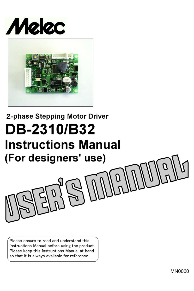
M-Elec DB-2310/B32 User manual
M-Elec
M-Elec C-875 User manual
M-Elec
M-Elec ML-2820-US3 User manual
M-Elec
M-Elec VALO ML-2836SDIM-US User manual

M-Elec
M-Elec AL-II Series User manual
M-Elec
M-Elec C-V870 User manual
M-Elec
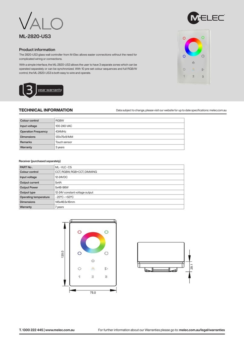
M-Elec Valo ML-2820-US3 User manual
M-Elec
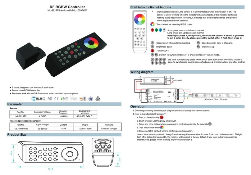
M-Elec ML-2819T8 User manual
M-Elec
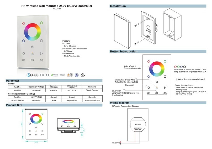
M-Elec ML-2820 User manual

M-Elec
M-Elec AL-2 Series User manual
Popular Controllers manuals by other brands
Karl Suss
Karl Suss CIC 1200 manual
Pontec
Pontec PondoSolar 250 Control operating instructions
ESP Safety
ESP Safety UPES-50D operating manual
Bernard
Bernard LE Series Installation, start-up and maintenance instructions
AXIOMATIC
AXIOMATIC AX032200 user manual
Mitsubishi
Mitsubishi AL2 Series Programming manual
