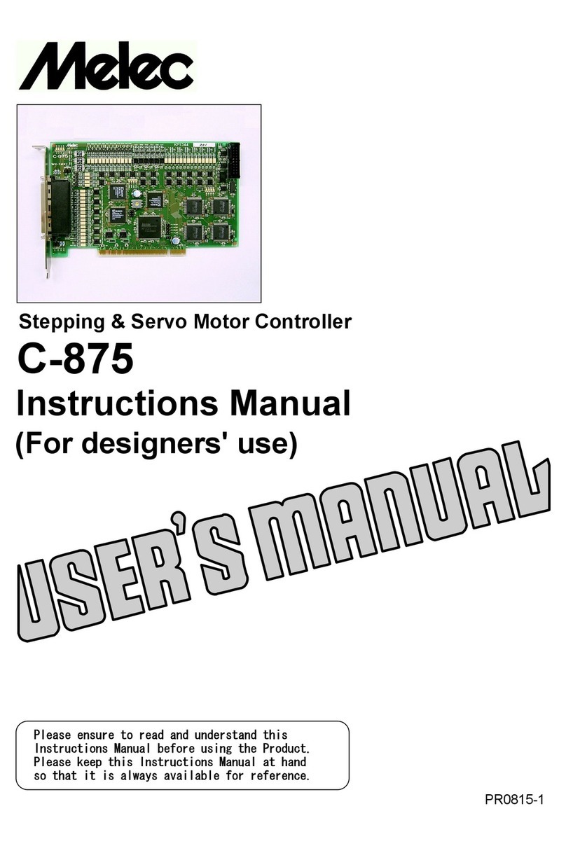
M-Elec AL-II Series User manual

AL-ⅡSeries Slave Controller
2C-776Av1
Instructions Manual
(For designers' use)
MN0194-1
Please ensure to read and understand this
Instructions Manual before using the Product.
Please keep this Instructions Manual at hand
so that it is always available for reference.

-2-
Introduction
This instructions manual explains the handling of "AL- Series Slave Controller 2C-776Av1 " ,Ⅱ
emphasizing the specifications to enable proper and safe use.
The manual is thus intended for designers of control systems using stepping motors or servo motors.
Before using the product, read this manual carefully for better understanding.
Keep the manual handy so that you can read it whenever you want.
The 2C-776Av1 allows axes to be controlled independently and therefore referred to each axis as follows
:
1st axis 2nd axis 3rd axis 4th axis
X-axis Y-axis Z-axis A-axis
This manual basically explains only the X-axis.
Description of safety
This product must be handled correctly.
Handling the product incorrectly may cause unexpected accidents resulting in personal injuries or
damage to your properties.
Many of those accidents can be avoided if you have advance information on dangerous situations.
This manual provides precautions where dangerous situations are predicted. The manual provides the
following alert marking and messages for this purpose:
This indicates a hazardous situation that could result in death or serious
WARNING
personal injury if you do not perform the procedure correctly.
This indicates a potentially hazardous situation that could result in personal
CAUTION
injury or physical damage if you do not perform the procedure correctly.
Before use
This product is not designed for use in the equipment related to nuclear power, aerospace equipment,■vehicles, marine vessels, medical equipment directly in touch with human body, equipment
anticipated to give a serious impact to properties, and other equipment required to provide high
reliability.
Take failsafe measures so that the whole system operates safely even if the input power causes an■error, a signal line is disconnected, or the main unit fails.
This product is equipped with a LIMIT overtravel signal and an FSSTOP signal to prevent■()
mechanical damage.
The default values of these signals are set to ACTIVE OFF B contact . Accordingly, even in a()
system configuration in which the FSSTOP and LIMIT signals are not used, pulses are not output
unless NORMAL ON GND connection is enabled.()
Be sure to use this product within the scope of the specifications described in this instruction manual■in accordance with the specification method described therein.
Set up the product before operating it.■Please refer to Section 3, "Setting."
Please refer to separate manual "AL- series device driver manual for Windows" also when you■Ⅱ
handle this product.
2C-776Av1
Instructions Manual

-3-
Introduction
Description of safety
Before use Contents PAGE
Overview1.1-1. Features 4
1-2. Product configuration 5
1-3. Example of system configuration 6
1-4. Function block diagram 7
1-5. Externals of product 9
Specifications2.2-1. General specifications 11
2-2. Communication specifications 11
2-3. Basic specifications 12
2-4. Applied specifications 14
2-5. Input and output signal table 15
1 Serial communication connector J1, J2 15() ( )
2 Power supply connector J3 15() ( )
3 Extend I/O communication connector J4 15() ( )
4 General-purpose I/O connector J5 16() ( )
5 Sensor connector J10: X-axis, J11: Y-axis, J12: Z-axis, J13: A-axis 16() ( )
6 Driver connector J6: X-axis, J7: Y-axis, J8: Z-axis, J9: A-axis 17() ( )
7 SIGNAL I/O connector J14 18() ( )
2-6. Input and output specifications 19
1 Output specifications 19()
2 Input specifications 21()
2-7. Outside dimensions 22
Setting3.3-1. Installation of device driver for Windows 23
3-2. Address setting of the AL- series S1 23Ⅱ()
3-3. Baud rate setting of the AL- series S2 23Ⅱ()
Installation and connection4.4-1. Installation 24
1 Installation distance 24()
2 Installation method 24()
4-2. Connection of AL- communication system 25Ⅱ
1 Core connection of AL- communications cable 25() Ⅱ
2 Connection of terminator 25()
3 Wiring distance of AL- communication 25() Ⅱ
4 Power supply and slave power supply for communication 25()
4-3. Connection example 26
1 Examples of connection to power supply 26()
2 Examples of connection to driver 27()
3 Examples of connection to sensor at photosensor 29() ( )
4 Examples of connection to general-purpose I/O 32()
5 Examples of connection to SIGNAL I/O 32()
6 Examples of connection to Extend I/O unit 32()
Maintenance5.5-1. Maintenance and inspection 33
1 Cleaning method 33()
2 Inspection method 33()
3 Replacement method 33()
5-2. Saving and disposal 33
1 Saving method 33()
2 Disposal method 33()
The main parts which revised by this manual
2C-776Av1
Instructions Manual

-4-
2C-776Av1
Instructions Manual
Overview1.
1-1. Features
The AL- series is a high speed serial communication system of original controlling the flexible stepping motor,●Ⅱ
servo motor which can cope easily as well and I/O in the decentralization of the device and supporting axial addition.
The AL- series is an insulation type high-speed serial communications of 20 Mbps/50 m or 10 Mbps/100 m.・Ⅱ
As a result, the saving wiring for the personal computer system can be attempted by the performance ratio of(
our company that equals a board controller so far.)
The shift of board controller C-VX870 series Device-function for PCI made of our company and the USB series・()
Device-function and Unit-function is easy depending on the device driver function for Windows.()
2C-776Av1 is a version up product with the 2C-776 upward compatibility.●The status of four axis batch reading and the command of four axis batch execution by the Unit-function became
possible. This Unit-function can perform a unit and AL- interface by one function execution from an application.Ⅱ
By this,
The time crunch can be done compared with accessed Device-function of each axis and I/O-function of・each I/O port.
The Unit-function writing suppresses the difference at time until it instructs time each axis and each I/O output・()
signal.
The Unit-function can reduce the load of the application.・It supports the Device-function, and can use the Device-function.・The Unit-function can be used together with the Device-function and the I/O-function.・
*1 The driver connection cable of 2C-776Av1 can correspond is only new ratings. Additionally, it is compatible with 2C-776.
Please refer to "Connection/ others " manual for the AL- series in detail.Ⅱ
Access example in Device-function and I/O-function Access example in Unit-function
Time lag
Reading X-axis STATUS1 X-axis STATUS1
Reading Y-axis STATUS1 Y-axis STATUS1
Reading Z-axis STATUS1 Z-axis STATUS1
Reading A-axis STATUS1 A-axis STATUS1
Time lag Batch Reading
Reading X-axis Control I/O A Unit X-axis Control I/O()
Reading Y-axis Control I/O Y-axis Control I/O
Reading Z-axis Control I/O Z-axis Control I/O
Reading A-axis Control I/O A-axis Control I/O
General-purpose I/O General-purpose I/OReading
Reading Extend I/O 0 Extend I/O 0
n
Reading Extend I/O 1 Extend I/O 1
o
n
i
o
t
Time lag
Batch Writing X-axis DATA1 X-axis DATA1
i
a
Each axis X-axis DATA2 X-axis DATA2
t
c
()
X-axis COMMAND -axis COMMAND
a
i
X
Batch Writing Y-axis DATA1 Y-axis DATA1
c
l
Each axis Y-axis DATA2 Y-axis DATA2
i
p
()
-axis COMMAND -axis COMMAND
l
p
Y Y
Batch Writing Z-axis DATA1 Z-axis DATA1
p
A
Each axis Z-axis DATA2 Batch Writing Z-axis DATA2
p
()
-axis COMMAND -axis COMMAND
A
ZAUnitZ()
Batch Writing A-axis DATA1 A-axis DATA1
Each axis A-axis DATA2 A-axis DATA2()
-axis COMMAND -axis COMMANDA A
Time lag
Writing X-axis Control I/O X-axis Control I/O
Writing Y-axis Control I/O Y-axis Control I/O
Writing Z-axis Control I/O Z-axis Control I/O
Writing A-axis Control I/O A-axis Control I/O
General-purpose I/O General-purpose I/OWriting
Writing Extend I/O 0 Extend I/O 0
Writing Extend I/O 1 Extend I/O 1

-5-
2C-776Av1
Instructions Manual
R1
2C-776Av1 is equipped with our chip controller MCC to enable motor control using simple commands.●It enables four independent drive or two axes linear interpolation drive fixed interpolation-axes or two axes・()
circular interpolation drive fixed interpolation-axes by an easy commands.()
()Moreover, it enable to optional axes liner interpolation drive. Applied function
After the command being executed is finished, the commands stored in the reservation register are executed・()sequentially. Then this function can be allowed continuous drive. Applied function
The 32-bit width address counter and the maximum output frequency of 6.5 MHz of the MCC enables high-precision,・high-speed positioning.
Also equipped with a multi-functional 32-bit pulse counter, and 16-bit pulse differential counter, the 2C-776Av1 has・a variety of application such as counting feedback pulses from the servo driver, detecting step-out of the stepping
motor with an encoder.
The applications also include interrupt output and external signal output using the comparator function of each
counter.
2C-776Av1 has the following I/O signal besides the servo interface.●It is equipped with the general-purpose I/O signal by two points for each.・In addition, connect an Extend I/O unit 16/16 points or 32/32 points by the serial communication without minding・()
address setting and add a general-purpose I/O and can control it.
An arbitrary status signal of X-axis or Y-axis can be output external equipment.・This can be used as a synchronized signal to the external equipment.
2C-776Av1 is a small and easy controller.●The DIN rail installation and the base installations can be done.・
1-2. Product configuration
Product name Rating Maker Quantity Remarks
()Controller 2C-776Av1 Melec Inc. 1 Main Unit
()Connector 51103-0300 Molex 1 For power supply connector Accessory
()Connector 51103-0600 Molex 4 For sensor connector Accessory
()Connector 51103-0700 Molex 1 For general-purpose I/O connector Accessory
()Contact 50351-8100 Molex 36 Accessory
()Cable clamp NPL-510 Kitagawa 1 For SIGNAL I/O Cable fixation Accessory
×− ()Screw M2.6 4 2 For sensor shield cable fixation Accessory
×− ()Screw M3 4 5 For driver shield cable fixation Accessory
For SIGNAL I/O shield cable fixation

-6-
2C-776Av1
Instructions Manual
1-3. Example of system configuration
PC
()OFF LINE Initial data edit/Kind operation
USB * 15 slave's unit can be connected by one master board.
AL- series slave unitAL- PCI master boardⅡⅡ
PC AL2-01v1/PCI etc. Stepping or servo2C-776Av1
Driver Motor
AL- communication cable SENSORⅡ
Slot in 20 Mbps/50 m or 10 Mbps/100 m CWLM,CCWLM,ORG,NORG,EA/EB signal/ Each axis
X-axis
Extend I/O Terminator CB-54/R
Device driver Insert core CB-52/3232MIL etc. Y-axis※
●()MPL-34-01vx.xx/AL2W32 *1 ZCAT2032-0930
Windows 2000 Extend I/O cable Trigger output・
Windows XP 32 bit CE-66-01/IO-A03 etc. Z-axis・()
Windows Vista 32 bit 32/32 points 5 Mbps/1 m or less・() ()
・()Windows 7 32 bit
Camera etc. A-axis
MPL-35-01vx.xx/AL2W64 *1●
・()Windows XP 64 bit
・()Windows Vista 64 bit
・()Windows 7 64 bit
*1 Version No. Please confirm the latest version of vx.xx at the manual of the device driver.…
AL- series prepared connectable cables easily.・Ⅱ
Please refer to the "connection / others" instruction manual for details of connection of the AL- series.Ⅱ
Example of other AL- seriesⅡ
Controller for General-purpose I/O General-purpose I/O
() ()Power supply relay board servo or stepping motor Controller with built-in driver Extend type Slave type
CB-55-01/PS-T35 2C-771v1 CB-53/1616-MIL 2CB-01v1/3232-MIL 2CB-02v1/1616-MIL2CD-7710v1/ADB5F30 2CD-7713v1/GDB5F40
4-distribution 4-axes 2-axes for 5-phase 2-axes for 5-phase Extend type Slave type Slave type・・・・・・・
output of DC 24 V For stepping or stepping motor stepping motor In:16-points In:32-points In:16-points・・・・
1 A/terminal simple servo 0.75 A/phase 1.4 A/phase Out:16-points Out:32-points Out:16-points・ ・・・・・
()3.5 A in total
J2
J1
10 201
AL2‑01/PCI1
MADEIN JAPAN
S1
4030 60300001
MADEIN JAPAN
PL1
PL2
PL3
PL4
J1 J2
J3 J4
J6J5
DC+24V
INOUT
INOUT
MADEINJAPAN
J4 J5 J3DC+24V
J8 J9 J10 J11
MADE INJAPAN
J14
J12 J13
J7J6
J2J1
J2J1
RDY
DC+24VJ5
SENSOR/YJ4SENSOR/XJ3
S3
S6 S4 S5
J7
MOTOR/X
J6
DC+24V/X S7
S10 S8 S9
J9MOTOR/Y
J8
DC+24V/Y
J10
J11 MADE IN JAPAN
MADE IN JAPA N
OUT IN
DC+24V
J4J3 J2
J1
GND
8
OUT +24V
KP1516‑0A
MADEIN JAPAN
1
4
1
IN
+24VGND
3.5A
MADE IN JAPAN
J7J15 J17J9J14 J16J8 J6
J5 J3DC+24V
J4
J2
J1
INJ6OUTJ5
J2J1
MADEIN JAPAN DC+24VJ3
J4
OUT INJ7 J8
J4 J3DC+24V
MADE IN JAPAN
J1 J2
J5 OUT J6 IN
CTO 503
40
OS CTO 503
40
OS
MADEIN JAPAN
RDY
CTO 503
40
OSCTO 503
40
OS
J9
S6 S5
MADEIN JAPAN
J5J4J3
J1
J8
J2
J6
J7
S4 S3

-7-
2C-776Av1
Instructions Manual
1-4. Function block diagram
2C-776Av1
Serial interface
J6control block
Pulse, Sensor X-axis driverX-axis
J10Drive control block Encoder
STOP X-axis sensor
X-axis Counter block
e
e
J7
c
n
l
Pulse, Sensor Y-axis driverJ1
a
i
o
Y-axis
J11
Ⅱ
f
L
r
Drive control block Encoder
STOP Y-axis sensor
-
r
t
e
L
e
n
n
J2 Y-axis Counter block
c
A
t
o
o
a
n
i
C
J8
I
t
f
Pulse, Sensor Z-axis driver
a
Ⅱ
Z-axis
r
J12
Ⅱ
l
-
Drive control block Encoder
e
STOP Z-axis sensor
-
o
L
tn
L
s
A
Z-axis Counter block
I
A
I
J9
Pulse, Sensor A-axis driverA-axis
J13Drive control block Encoder
r
STOP A-axis sensor
es
A-axis Counter block
U
Serial interface
control block J5
FSSTOPGeneral-purpose I/O
IN0, IN1
e
・In :2-Points
General-purpose
O
c
l
・Out:2-points
OUT0, OUT1 inputs
/
a
o
()Contains Extend I/O
General-purpose
I
f
r
・()In :32-Points max.
outputsJ4
r
t
・()Out:32-points max.
()
d
e
n
Control I/O area
Driver connector
n
t
o
・In :S.RDY/Eachaxis
/Each axis
e
n
C
・Out: S.ON, A.CLR / Each axis
t
I
x
d
J14
E
d
n
SOUT0, SOUT1
n
e
SIGNAL I/O block
()
e
t
Applied function
Output: 2 points
t
x
・
SIGNA I/O outputs
x
E
()
E
Camera trigger etc.
()Inside power supply
DC/DC
+24 VJ3
()Power Power supply for outside interface
supply

-8-
2C-776Av1
Instructions Manual
Serial interface control block
This department is control block for AL- serial communication.Ⅱ
The AL- serial communications interface department is insulated with +24 V power supply and the internal logics.Ⅱ
Serial interface control block
This department is control block for serial communication of Extend unit.
This block performs an Extend I/O unit and serial communication and can extend the I/O of 32 points /32 points
input output at the maximum .()
The serial communication interface part is insulated from power supply +24 V.
Drive control block
The drive control block outputs serial pulses to the motor driver from pulse generator MCC.
()MCCismadebyMELECInc.
This department detects origin sensor and a limit sensor signal and motor is controlled.・Enables four axes independent drive, or two axes X-axis and Y-axis, Z-axis and A-axis linear interpolation drive,・()
and circular interpolation drive.
Enables stop four axes at immediate stop by FSSTOP signal from the outside.・
To distinguish four axes, it is named X-axis, Y-axis, Z-axis, and A-axis.
Counter block
The counter block has three types of counters: ADDRESS COUNTER, PULSE COUNTER, and DFL COUNTER.
()Can use as hard timer.
ADDRESS COUNTER, PULSE COUNTER has 32-bit counter, and DFL COUNTER has 16-bit counter.
The 2C-776Av1 has a variety of application such as counting feedback pulses from the servo driver, detecting step-
out of the stepping motor with an encoder.
The applications also include interrupt output and external signal output using the comparator function of each
counter.
General-purpose I/O block
This block is controlling the following input/output.
These input/output ports can control easily by I/O-function.
General-purpose I/O area・The reading of the general-purpose Input IN0 signal and IN1 signal, the operation of the general-purpose…output OUT0 signal and OUT1 signal are possible.
Moreover, enables operation as Latch signal and Clear signal of X-axis SS0 signal by the IN0 signal input.
And, enables operation as Latch signal and Clear signal of Y-axis SS1 signal by the IN1 signal input.
Extend I/O area・When the area secure an extension input/output area for 32 points /32 points input/output and access it…from an application in this input/output area, the area can control input/output by an Extend I/O unit
and cyclic communication.
Control I/O area・The interface of SERVO ON, ALARM CLEAR, and SERVO READY signal is possible as the servo driver's…control I/O.
This Control I/O signal is reflected in each servo interface signal of the driver connector.
()
SIGNAL I/O block Applied function
This is a block where the external equipment such as cameras etc. and the interface can be done by open
collector output or line driver differential output signal.()
An arbitrary status signal of X-axis or Y-axis default value = CNTINT can be output external equipment.()
A real-time system with which OS of the personal computer doesn't relate is possible according to this interface.
User Interface block
This department is interface block for the motor drivers, sensor signals, and general-purpose input and output
equipment.

-9-
2C-776Av1
Instructions Manual
R11-5. Externals of product
J1, J2 These are shield connector of the RJ-45 type that connects the AL- communication.Ⅱ
J1 and J2 are connected with each unit and the communications cable can be connected in
the multidrop.
J3 This is a connector to connect +24 V power supply.
J4 This is a connector to connect an Extend I/O unit Option .()
J5 This is a connector that connects immediate stop FSSTOP signals and general-purpose I/O()
IN0, IN1, OUT0, and OUT1 signals .()
J6, J7, J8, J9 These are general purpose connector of MIL26 pin for the interface to the driver.
J6 is the one for the X-axis, J7 is one for the Y-axis, J8 is one for the Z-axis,
and J9 is the one for the A-axis.
J10, J11, J12, J13 These are connector to connect the sensor signals such as the LIMIT signal or the ORG signal.
J10 is the one for the X-axis, J11 is one for the Y-axis, J12 is one for the Z-axis,
and J13 is the one for the A-axis.
J14 This is a connector to SIGNAL I/O.
It is a connector where the external equipment and the interface can be done by open collector
output or line driver output signal.
An arbitrary status signal of X axis or Y axis default value = CNTINT can be output.()
(J13)
(J12)
(J10)
(J11)
ADDRESS
(J1) (J2) (J3)
(J5)
11
(J4)
RATE
(J14)
J10 J11
J9J8
DC+24V
J3
J5J4
J1 J2
J6 J7 J12 J13
J14
MADE IN JAPAN

-10-
2C-776Av1
Instructions Manual
S1 This is a setting switch of the slave address of the AL- communication.Ⅱ
S2 This is a setting switch of the baud rate of the AL- communication.Ⅱ
LED RDY RDY LED Green color turns on at the time of RDY state of each axis.() ( )
Terminal The terminal connect to the shield when the driver cable of shield.
Use the screw of attached M3 4.×
Terminal The terminal connect to the shield when the sensor cable of shield.
Use the screw of attached M2 .6 4.×
Terminal The terminal connect to the shield when the SIGNAL I/O cable of shield.
Use the screw of attached M3 4.×
()
Base installation These are part that fixes the main unit to the installation base. two places
part Use the M3 screw.
Moreover, it is possible to install it in the DIN rail with a exclusive use DIN attachment lug.
Please refer to the connection/other manual for details.
Cable clamping Fix the cable clamping accessory into this hole when you connect the cable for SIGNAL I/O()
installation hole connector J14 .()
Connector for This is a connector for adjustment of the main unit.
adjustment Do not connect anything.

-11-
2C-776Av1
Instructions Manual
Specifications2.
2-1. General specifications
No. Item Specifications
(± )1 Supply voltage DC +24 V less than 10 % of the power supply voltage
2 Power consumption 800 mA or less *1
*1 The value when the main unit supplies the power supply for the sensor is indicated.
The main unit current consumption is 220 mA.
Example: at the sensor of the current consumption 25 mA,
and the servo driver connection.
4 25 mA 4 axes 400 mA・××=pieces
Three signal by S.ON, A.CLR, and DRST are on 8 mA 4 axes 96 mA
・()××=
The total current 220 mA 400 mA 96 mA 716 mA・ =++=
The totaled current consumption must not exceed 800 mA.
・℃〜+ ℃3 Operating ambient 0 40
・% ( )temperature and 80 RH or less without dew condensation
humidity
・℃〜+ ℃4055Storage temperature ・% ( )and humidity 80 RH or less without dew condensation
5 Installation Inside a well-ventilated cabinet installed indoor, free from direct sunlight.・
environment Not exposed to corrosive and flammable gasses, and not affected by oil mist,・dust,salt, iron powder, water, and chemicals.
Not subject to constant vibration or excessive shock.・Not affected by electromagnetic noise caused by power equipment.・Free of radioactive materials and magnetic fields, and not in vacuum.・
()6 Dimensions W 43.5 × H 96 × D 124 mm
7 Weight Approx. 0.3 kg
2-2. Communication specifications
No. Item Specifications
Ⅱ・ ()1 AL- interface Conformity standard :RS485 insulation type
Transmission protocol :Protocol for AL- communication・Ⅱ
・〜( 〜)Slave connection number :1 15 slave slave address setting range: H' 1 H' F
()()・Wiring distance/baud rate :100 m 10 Mbps / 50 m 20 Mbps
・( )2 Extend interface Conformity standard :RS485 non-insulation: but there is insulation with +24 V.
Connection number :Up to one unit・Wiring distance/baud rate :1 m/5 Mbps・

-12-
2C-776Av1
Instructions Manual
2-3. Basic specifications
No. Item Specifications
1 Number of Four axes
control axes
2 Pulse output Output type Independent direction output/ Specified direction output/・
function Phase-differential signal output
Line driver output・
Output frequency Independent drive 0.1 Hz to 6.5 MHz・:
Interpolation drive 0.1 Hz to 5 MHz・:
()Acceleration/deceleration 5000 ms/kHz to 0.0025 ms/kHz Trapezoid/S-curve
time constant
Acceleration/deceleration Trapezoid・
・( )shape S-curve This feature enables to set asymmetrical shape.
Triangular drive prevention During S-shaped acceleration/deceleration drive, INDEX drive may end
function before the maximum speed is reached.
In this event, triangular drive can be automatically avoided.
Number of output pulses JOG drive : -65,535 to +65,535 pulse・SCAN drive : Up to infinite pulses・INDEX drive : -2,147,483,647 to + 2,147,483,647 pulses・
3 Encoder Input type Incremental・()function Independent direction input/ Phase-differential signal input
Line receiver input・
Input range 5 MHz〜
External signal output External signals such as hand pulser signals that are input to the EA and
EB signals can be output as CWP and CCWP signals.
4 Drive function JOG drive Pulses are constantly output until the specified pulses.
SCAN drive Pulses are continuously output until a stop command is detected.
INDEX drive Pulses are output until the specified relative or absolute address is
reached.
ORIGIN drive The specified drive processes are performed.
This drive is finished when the ORG signal specified edge is detected.
2-axis linear interpolation Linear interpolation is performed toward the specified coordinates from・
drive the current coordinates.
Driving type is selected from INDEX drive or SCAN drive.・Positional errors for the specified straight line are 0.5 LSB.・±
The absolute and relative addresses that can be specified for・coordinates range from -2,147,483,647 to +2,147,483,647 32 bits .()
2-axis circular Circular interpolation is performed toward the specified coordinates・
interpolation drive from the current coordinates on the circular curve specified by the
center-point or passing-point coordinates.
Driving type is selected from INDEX drive or SCAN drive.・Max speed is 5 MHz.・Positional errors for the specified circuit curve are 1 LSB.・±
The relative addresses range from -8,388,607 to +8,388,607 24 bits .・()
Short axis pulses range from -2,147,483,648 to +2,147,483,647・32 bits .()
Linear speed constant Control is performed to keep the synthesized speed of the two axes
control working for interpolation drive constant.

-13-
2C-776Av1
Instructions Manual
No. Item Specifications
5 Stop function Slow stop function SLOW STOP command・Detection of a match of the comparator of each counter.・Deceleration stop by DALM signal.・
Immediate stop function FAST STOP command・
・()FSSTOP signal four axes stop
Detection of a match of the comparator of each counter.・Immediate stop by DALM signal.・
LIMIT signal direction stop●+
Immediate stop by CWLM signal and slow stop can be selected.・Slow stop or immediate stop can be performed for each axis upon・detection of a match of the comparator COMP2 of each counter.()
direction stop●-
Immediate stop by CCWLM signal and slow stop can be selected.・Slow stop or immediate stop can be performed for each axis upon・detection of a match of the comparator COMP3 of each counter.()
6 Counter ADDRESS COUNTER 32-bit counter that manages absolute addresses by counting drive output
function pulses.
PULSE COUNTER 32-bit counter that counts the drive pulse output or an encoder feedback
pulses.
DFL COUNTER 16-bit counter that detects differences in the number of pulses by・counting external pulse signals and encoder feedback pulses.
It can also be used as a 16-bit timer.・
Comparator function Detection of a match of the three comparators of each counter.
Upon detection of a match by the comparator, pulse output can be・decelerated and then stopped, or stopped immediately.
Upon detection of a match by the comparator, status can be read.・The detection signal can be external status signal output.・
AUTO CLEAR function The counter can automatically be cleared upon detection of a match of
COMP1 of each counter.
AUTO ADD function If the counter value reaches the COMP1, a value that is set by the data
add to COMPARE REGISITER1 of each counter.
7 Other For servo driver signal The following signals are prepared as a signal for the servo.
・()functions In-position signal input/ Phase signal input DEND/PO
・()Servo ready signal input S.RDY
・()Driver alarm signal input DALM
・()Servo reset signal output DRST
・()Servo on signal output S.ON
・()Alarm clear signal output A.CLR
General-purpose I/O Two points of input/output are prepared as general purpose I/O.
Data reading function Current status information can be read in real time.
Current status information includes status data, count data of a counter
etc.

-14-
2C-776Av1
Instructions Manual
2-4. Applied functions
No. Item Specifications
1 Drive UP/DOWN/CONST drive CHANGE Drive change for acceleration, deceleration, or constant speed・
function function can be performed upon detection of signal at an arbitrary
change operation point.
SPEED CHANGE function The drive pulse speed is changed upon detection of signal at・an arbitrary change operation point.
RATE CHANGE function The rate is changed upon detection of signal at an arbitrary・change to the specified rate.
INDEX CHANGE function Upon detection of signal at an arbitrary change operation point,・the stop position at which drive is to be finished is changed.
Upon detection of the INC INDEX CHANGE command, the・system performs INC INDEX drive by setting the specified data
at the stop position of the relative address for which the start
position is the origin.
Upon detection of the ABS INDEX CHANGE command, the・system performs ABS INDEX drive by setting the specified
data at the stop position of the absolute address managed with
the address counter.
Optional axes liner interpolation Linear interpolation is performed toward the specified coordinates
drive from the current coordinates. Then long axis outputs pulses.
INDEX drive control the start point This function is allowed to set OFFSET of the start point at auto
at auto deceleration deceleration. This function can be used when INDEX drive, liner
interpolation and INDEX drive.
2 Count Ring counter function The address counter, pulse counter each are a ring counter in
function which any maximum count can be set.
Count data latch/clearance function This function latches count data of a counter at a specific latch
timing and holds it till the next latch timing.
Each counter can latch counter value at arbitrary timing.
It is possible to clear a counter value at the latch timing.
IN0 signal: for X-axis
IN1 signal: for Y-axis
Data reading Current status information includes setting data of X-axis or
Y-axis, latch data of a counter etc.
3 Other Command reservation function Each axis has a reservation register that can store data
functions commands for ten instructions.
General-purpose commands of drive commands can be・reserved in the reservation register.
After the command being executed is finished, the commands・stored in the reservation register are executed sequentially.
Then this function can be allowed continuous drive.
Input signal logical switch function The logic of the following input signals can be changed:
CWLM signal・CCWLM signal・DALM signal・FSSTOP signal・
External signal output The COMPARE REGISITER corresponding signal of the・counter can be output from the J14 connector.
The SOUT0 signal is a comparator of X-axis counter.
The SOUT1 signal is a comparator of Y-axis counter.
If the signal that influences the delay of AL- communication・Ⅱ
and OS inputs this signal output to the external instrument of
the trigger signal etc. of the camera, a real-time synchronous
control becomes possible.
The output time width of COMPARE REGISITER of each・counter can set 1 ms or less according to the response of an
external circuit.
Please refer to the chapter of the AL- series device driver manual application function for details of※Ⅱ
applied specification.

-15-
2C-776Av1
Instructions Manual
2-5. Input and output signal table
() ( )1 Serial communication connector J1, J2
●()Connector :RJ-45 shield type
●□□□□(〜)Recommendation cable :KB-STP- L : length 30 m or less
()Made by Sanwa Supply: It is not an accessory.
Reference
For more information about a cable preparing in the
AL- series and a recommended cable, refer to theⅡ
instruction manual of "connection / others" .
No. Signal name DescriptionDirection
1 N.C Connection is prohibited.−
2 N.C Connection is prohibited.−
()3 I/O +AL Ⅱ+ side input/output signal of the serial data line driver positive logic
Ⅱ()4 I +V Power supply for AL- communication +6 V
Ⅱ()5 I -V GND for AL- communication 0 V
()6 I/O -AL Ⅱ- side input/output signal of the serial data line driver negative logic
7 N.C Connection is prohibited.−
8 N.C Connection is prohibited.−
J1 and J2 are the same terminal arrays. It is possible to connect with either.・When the multidrop is connected, the divergence connection is done to other slave equipment through・J1 or the J2 connector.
() ( )2 Power supply connector J3 ●()Connector : 53426-0310 Molex
●()
()Contact insertion side Conformity connector : 51103-0300 Molex: accessories
●()Conformity contact : 50351-8100 Molex: accessories
●()Conformity crimp tool : 57295-5000 Molex
Acceptable wire : AWG28 AWG22●〜
(φ〜φ)Coating 1.15 1.8
Conformity cable : CE-76/003C10-51103●()1 m: It is not an accessories.
No. Signal name DescriptionDirection
1 I +24 V DC +24 V power supply
2 GND GND of +24 V power supply−
3 F.G Frame GND is connected with case.−
() ( )3 Extend I/O communication connector J4
●()Connector : 1565994-4 e-CON: Tyco Electronics
●()Conformity cable : CE-66-01/IO-A03 0.3 m, It is not an accessories.
(): CE-66-02/IO-A10 1 m, It is not an accessories.
No. Signal name DescriptionDirection
()1 I/O + RS485 EXT() + side signal of the Extend I/O serial data line driver positive logic
()2 I/O - RS485 EXT() - side signal of the Extend I/O serial data line driver negative logic
3 S.G Signal GND for Extend I/O−
4 F.G Frame GND is connected with case.−
Number of Extend I/O that can be connected from J4 is one unit.・
J1 J2
8 7 6 5 4 3 2 1 8 7 6 5 4 3 2 1
1
123
J3DC+24V
1
J4
1

-16-
2C-776Av1
Instructions Manual
R1
() ( )4 General-purpose I/O connector J5
●()Connector : 53426-0710 Molex
●()Conformity connector : 51103-0700 Molex: accessories
●()Conformity contact: : 50351-8100 Molex: accessories
●()
()Contact insertion side Conformity crimp tool : 57295-5000 Molex
Acceptable wire : AWG28 AWG22●〜
(φ〜φ)Coating 1.15 1.8
No. Signal name DescriptionDirection
−()1 R.GND Return GND of each signal for +24 V interface
()2 I FSSTOP Immediate stop signal of all axes B contact
3 I IN0 General-purpose input 0
4 I IN1 General-purpose input 1
5 O OUT0 General-purpose output 0
6 O OUT1 General-purpose output 1
7 N.C Connection is prohibited.−
The default values of the FSSTOP signal is ACTIVE OFF input B contact .・()
()The pulse is not output if it doesn't connect into the status of NORMAL ON GND connection
when signal unused.
() ( )5 Sensor connector J10: X-axis, J11: Y-axis, J12: Z-axis, J13: A-axis
●()Connector : 53426-0610 Molex
●()Conformity connector : 51103-0600 Molex: accessories
●()Conformity contact : 50351-8100 Molex: accessories
●()Conformity crimp tool : 57295-5000 Molex
Acceptable wire : AWG28 AWG22●〜
(φ〜φ)Coating 1.15 1.8
()Contact insertion side
()For shield connection M2.6 tap
No. Signal name DescriptionDirection
() ( )1 I CWLM + CW direction LIMIT signal B contact
() ( )2 I CCWLM - CCW direction LIMIT signal B contact
3 I NORG Machine origin proximity signal
4 I ORG Machine origin signal
5 GND Power supply GND for sensor−()
6 O EXTVCOM+ Power supply +24 V for sensor *1()
*1 Do not use it as power supplies other than SENSOR. Moreover, an output electrical overload and short circuit
should be careful. An internal protection circuit fuse is blown.()
The sensor connector is the same terminal array for all axes.・The default values of the LIMIT signal of each axis are ACTIVE OFF input B contact .・()
()The pulse is not output if it doesn't connect into the status of NORMAL ON GND connection
when signal unused.
+24 V power supply GND and internal can be connected, and can use as power supply GND for return GND・of sensor.
GND and +24 V power supply GND is mutually connected internally.・These can be used as power supply GND for return GND and sensor.
It can supply EXTVCOM+ as a power supply for sensor to the +24 V Max 150 mA/axis.・()There is an overcurrent protection circuit.
When user drops the shield of a cable for sensor, user uses a terminal in the sensor connector side,・and please connect it.
J5
1
1
1
23
4567
11
1
1
(J13) (J12)
(J11) (J10)
1
1
23
45
6
1123456

-17-
2C-776Av1
Instructions Manual
R1
() ( )6 Driver connector J6: X-axis, J7: Y-axis, J8: Z-axis, J9: A-axis
●()()Connector : HIF3BA-26PA-2.54DS 71 Hirose Denki
Conformity cable : Various driver connection cables are prepared.●Please refer to the "Connection/others" manual
Ⅱ( )of the AL- series. It is not an accessory.
()For shield connection M3 tap
No. Signal name DescriptionDirection
−()1 S.G Signal GND Return GND of line driver/line receiver
2 O N.C Connection is prohibited.
()The output circuit is allocated.
3 O CWP + CW direction positive logic pulse()
4 O CWP + CW direction negative logic pulse()
5 O CCWP - CCW direction positive logic pulse()
6 O CCWP - CCW direction negative logic pulse()
7 O DRST/M.F Servo reset signal when the servo driver.
Motor current free signal when the stepping driver.
()It is possible by general-purpose output.
8 O DRSTCOM For current output +24 V of DRST()
9 I +ZORG +Z-phase signal of encoder
10 I -ZORG -Z-phase signal of encoder
11 I DEND/PO Position completion signal when the servo motor driver.
Phase out signal when the stepping motor driver.
12 R.GND Return GND−
13 I N.C Connection is prohibited.
()The input circuit is allocated.
14 N.C R.GND Connection is prohibited.−()
()The R.GND of input circuit is allocated.
15 I S.RDY Servo ready signal
()It is possible by general-purpose input.
16 R.GND Return GND−
17 I DALM Driver alarm signal
()It is possible by general-purpose input.
18 R.GND Return GND−
19 I +EA +A-phase signal of encoder
20 I -EA -A-phase signal of encoder
21 I +EB +B-phase signal of encoder
22 I -EB -B-phase signal of encoder
23 O S.ON Servo on signal
()It is possible by general-purpose output.
24 O A.CLR Alarm clear signal
()It is possible by general-purpose output.
25 O EXTVCOM+ For the power supply +24 V of driver interface *1()
26 N.C Connection is prohibited.−
*1 Do not use it as power supplies other than a driver interface. Moreover, an output electrical overload and
short circuit should be careful. An internal protection circuit fuse is blown.()
The driver connector is the same terminal array for all axes.・The default values of the DALM signal of each axis are ACTIVE OFF input B contact .・()
The setting and B contact input of the halt function by the DALM signal detection can be switched to
A contact input.
It can supply EXTVCOM+ as a power supply for driver interface to the +24 V Max 30 mA/axis.・()There is an overcurrent protection circuit.
S.ON, the A.CLR output, and the S.RDY input of Control I/O can be controlled with general-purpose I/O・and Extend I/O according to the I/O-function or the Unit-function.
2
1
J9J8
J6 J7
2
11
2
2
1

-18-
2C-776Av1
Instructions Manual
() ( )7 SIGNAL I/O connector J14
●()()Connector : DF11-16DP-2DS 52 Hirose Denki
●()Conformity cable : CE-70-01/IO-16C12 1.2 m, for open collector output
(): CE-70-02/IO-16C50 5 m, for line driver output
()Each cable is not an accessory.
No. Signal name DescriptionDirection
()1 O +SOUT0 X-axis SOUT signal output default value CNTINT
()
Line driver positive logic
()2 O -SOUT0 X-axis SOUT signal output default value CNTINT
()
Line driver negative logic
()3 O +SOUT1 Y-axis SOUT signal output default value CNTINT
()
Line driver positive logic
()4 O -SOUT1 Y-axis SOUT signal output default value CNTINT
()
Line driver negative logic
()5 O SOUT0 X-axis SOUT signal output default value CNTINT
()Open collector output
−()6 R.GND GND for return of signal +5 V GND of internal
()Return GND
()7 O SOUT1 Y-axis SOUT signal output default value CNTINT
()Open collector output
−()8 R.GND GND for return of signal +5 V GND of internal
()Return GND
()9 O N.C Connection is prohibited. Output circuit of unpublic
Do not connect anything.
−()10 R.GND GND for return of signal +5 V GND of internal
()Return GND
I()11 N.C Connection is prohibited. Input circuit of unpublic
Do not connect anything.
−()12 R.GND GND for return of signal +5 V GND of internal
()Return GND
I()13 N.C Connection is prohibited. Input circuit of unpublic
Do not connect anything.
−()14 R.GND GND for return of signal +5 V GND of internal
()Return GND
−()15 S.G Signal GND +5 V GND of internal
16 N.C Connection is prohibited.−
The status signal of X-axis and Y-axis can be output by setting the status outside output function.・The default value of the output when the power supply is turned on is CNTINT of each axis.
As for the output signal, the open collector output or the line driver output can be selected.・
(J14)
1
2

-19-
2C-776Av1
Instructions Manual
R12-6. Input and output specifications
1 Output specifications()
Output specification 1●
Circuit Description
Signal name CWP, CWP, CCWP, CCWP+5 V
Max. Line driver differential output
()
Output method
20 mA ()
CWP, CCWP Equivalent to 26C31: Compliant with RS422A
→Output←
20 mA±
CWP, CCWP currentEquivalent
to 26C31 Output
()Maximum 6.5 MHz Indipendent drive
frequency
S.G
Insulation Non-insulatedSame for all axes.
Output specification 2●
Circuit Description
Signal name DRST
Interface +24 V
+24 V voltage
DRSTCOM
Nch transistor1.65 K ΩMax.15 mA Output method Open collector output
(= )
DRST ON : 30 mA Vce 1 V or less
←
(= )
Max. 30 mA Output current 50 mA Vce 2 V or less
Photocoupler OFF: 0.1 mA or less
Output 1 ms or less
(→、→)response time ON OFF OFF ON
Same for all axes. Photocoupler isolation
Insulation ()Between internal circuits and external circuits.
Output specification 3●
Circuit Description
Signal name Servo faction+24 V ●
*1 EXTVCOM+ S.ON, A.CLR〜
()
EXTVCOM+ can be supplied by 24V for the driver: Up to 35 mA
S.ON, A.CLR
General-purpose faction←●
Max. 30 mA
OUT0 , OUT1Photocoupler
Interface +24 V
voltage
Same for all axes. Nch transistor+24V Output method Open collector output
(= )
OUT0, OUT1 ON :30mA Vce 1Vorless
←
(= )
Max. 30 mA Output current 50 mA Vce 2 V or less
Photocoupler OFF : 0.1 mA or less
Output 1 ms or less
Two points for the unit. (→、→)response time ON OFF OFF ON
Photocoupler isolation
Insulation ()Between internal circuits and external circuits.
*1 An output electrical overload and short circuit should be careful.
An internal protection circuit fuse is blown.()

-20-
2C-776Av1
Instructions Manual
Output specification 4●
Circuit Description
Signal name SOUT0 , SOUT1
Interface +30 V or less
voltage
Output method Open collector output
SOUT0, SOUT1
Trigger output to externalEquivalent to LS06 ((= )equipment etc.)ON :10 mA Vce 0.6 V or less
Output current OFF :0.3 mA or less
S.G
()Output 1 s or lessμTheoutputtimewidthcanbeset.
()5V GND of internal (→、→)response time ON OFF OFF ON
Insulation Non-insulation
Signal name SOUT0, SOUT1+5 V ±±
Line driver outputMax. Output method
()20mA Equivalent to 26C31: Compliant with RS422A
+SOUT0, +SOUT1
→Output current 20 mA←±
-SOUT0, -SOUT1
Equivalent to (()26LS31 Trigger output to external The output time width can be set.Output 1 s or lessμ
)
equipment etc. (→、→)response time ON OFF OFF ON
S.G
Insulation Non-insulation
It is a signal of the J14 connector.
The status signal of X-axis and Y-axis can be output by setting the status outside output function.・The default value of the output when the power supply is turned on is CNTINT of each axis.
As for the output signal, the open collector output or the line driver output can be selected.・The signal with different interface specification can be connected.
Other manuals for AL-II Series
1
This manual suits for next models
2
Table of contents
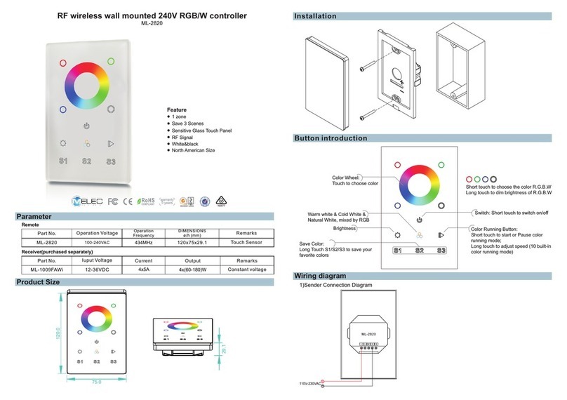
Other M-Elec Controllers manuals

M-Elec
M-Elec ML-2819T8 User manual

M-Elec
M-Elec C-V870 User manual

M-Elec
M-Elec VALO ML-2836SDIM-US User manual

M-Elec
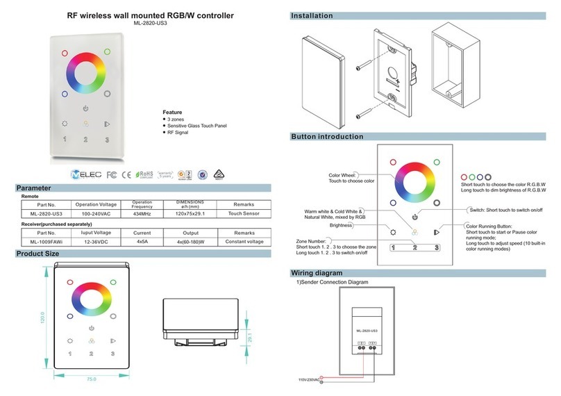
M-Elec ML-2820 User manual

M-Elec
M-Elec C-VX875 User manual

M-Elec
M-Elec C-875 User manual

M-Elec
M-Elec DB-2310/B32 User manual

M-Elec
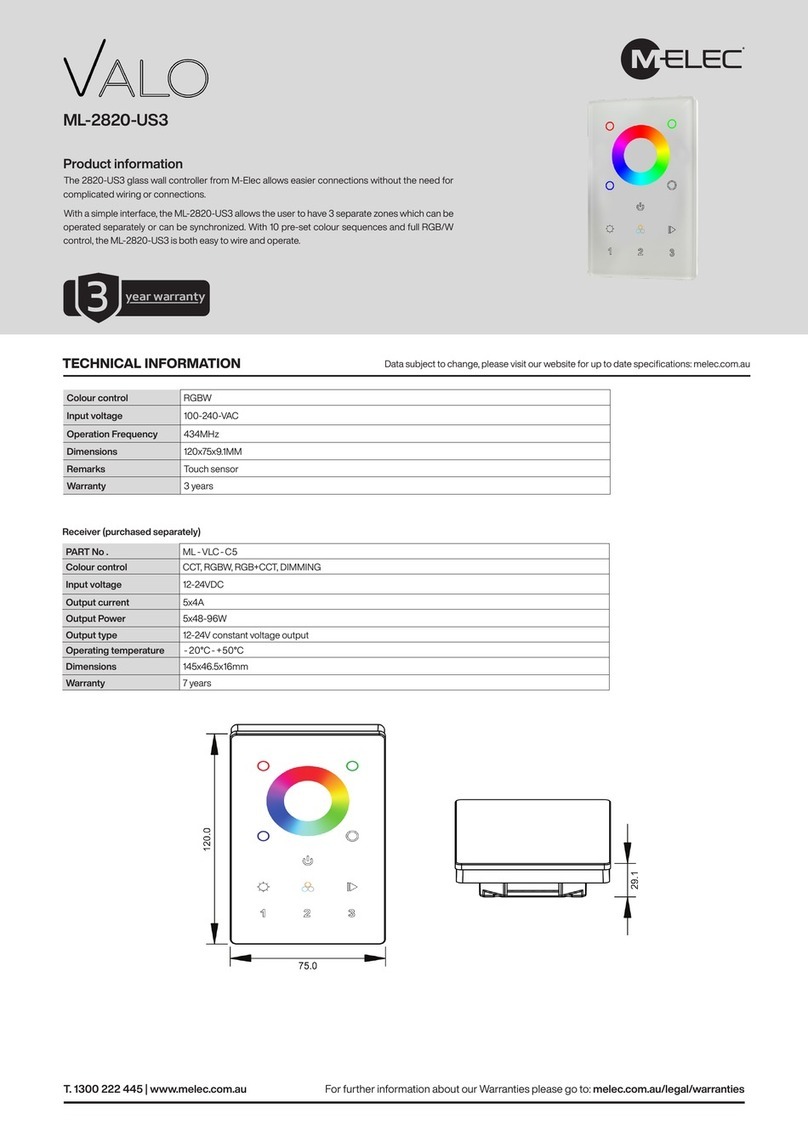
M-Elec ML-2820-US3 User manual

M-Elec
M-Elec Valo ML-2820-US3 User manual

M-Elec
M-Elec AL-2 Series User manual