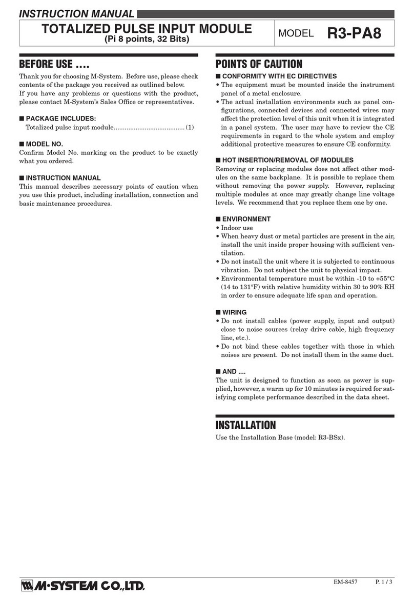
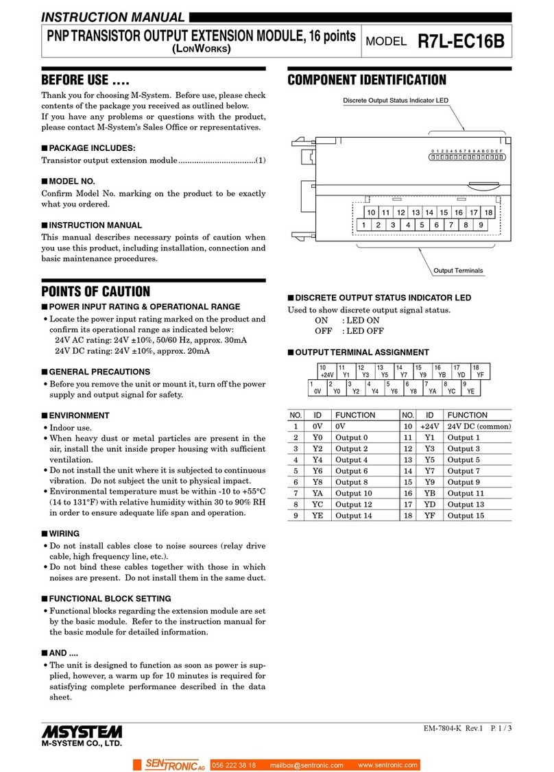
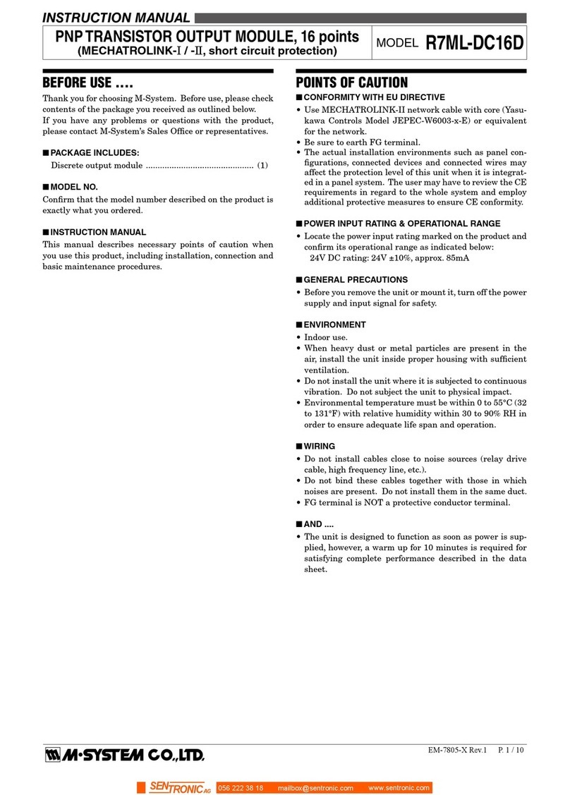
manuals.online logo
Brands
  1. Home
  2. •
  3. Brands
  4. •
  5. M-system
  6. •
  7. Control Unit
  8. •
  9. M-system R7E-EA8 User manual

M-system R7E-EA8 User manual

R7E-EA8
P. 1 / 2
EM-7807-N Rev.2
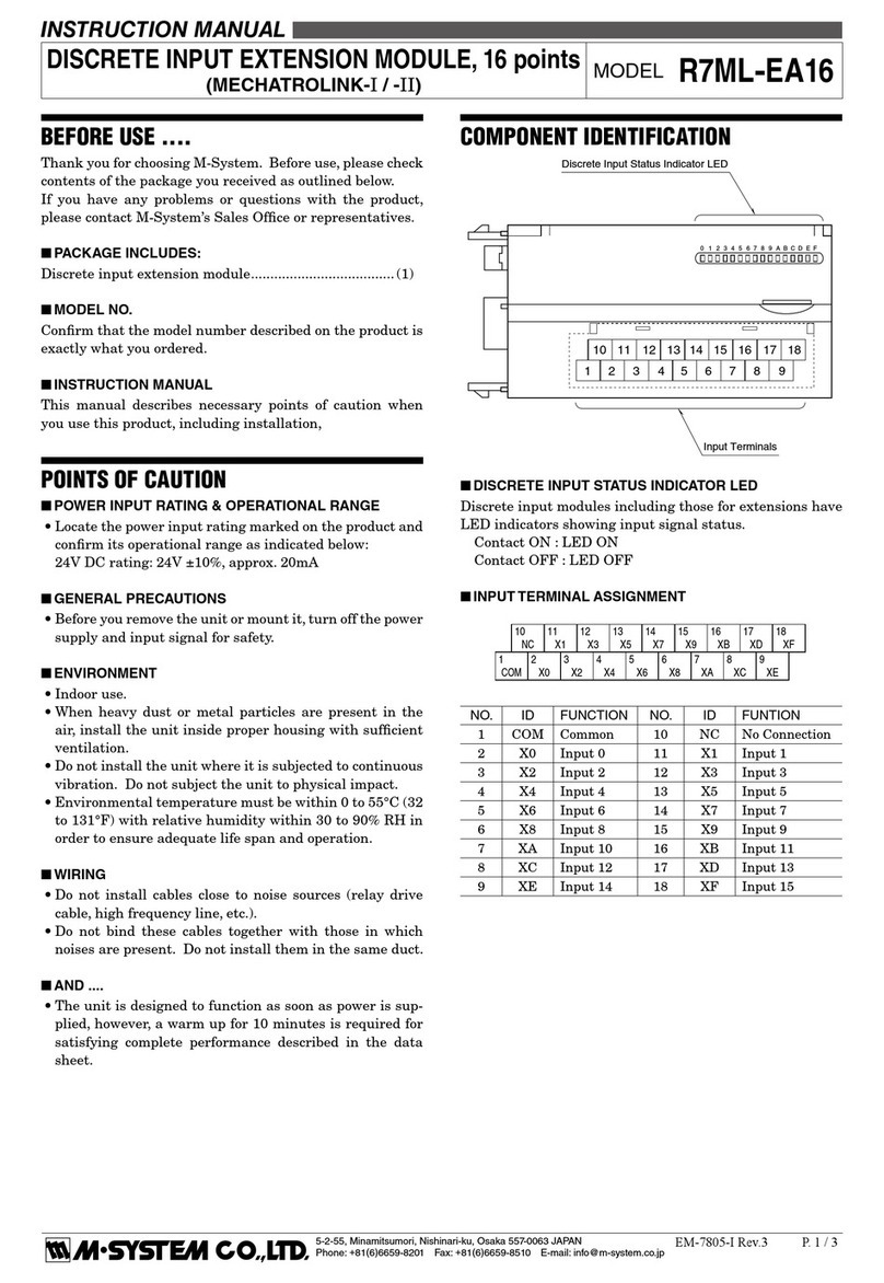
DISCRETE INPUT EXTENSION MODULE, 8 points
(Ethernet Modbus/TCP) MODEL R7E-EA8
INSTRUCTION MANUAL
BEFORE USE ....
Thank you for choosing M-System. Before use, please check
contents of the package you received as outlined below.
If you have any problems or questions with the product,
please contact M-System’s Sales Office or representatives.
■PACKAGE INCLUDES:
Discrete input extension module..................................... (1)
■MODEL NO.
Confirm that the model number described on the product is
exactly what you ordered.
■INSTRUCTION MANUAL
This manual describes necessary points of caution when
you use this product, including installation, connection and
basic maintenance procedures.
POINTS OF CAUTION
■CONFORMITY WITH EU DIRECTIVES
•The actual installation environments such as panel con-
figurations, connected devices and connected wires may
affect the protection level of this unit when it is integrat-
ed in a panel system. The user may have to review the CE
requirements in regard to the whole system and employ
additional protective measures to ensure CE conformity.
■POWER INPUT RATING & OPERATIONAL RANGE
•Locate the power input rating marked on the product and
confirm its operational range as indicated below:
24V DC rating: 24V ±10%, approx. 10mA
■GENERAL PRECAUTIONS
•Before you remove the unit or mount it, turn off the power
supply and input signal for safety.
■ENVIRONMENT
•Indoor use.
•When heavy dust or metal particles are present in the
air, install the unit inside proper housing with sufficient
ventilation.
•Do not install the unit where it is subjected to continuous
vibration. Do not subject the unit to physical impact.
•Environmental temperature must be within -10 to +55°C
(14 to 131°F) with relative humidity within 30 to 90% RH
in order to ensure adequate life span and operation.
■WIRING
•Do not install cables close to noise sources (relay drive
cable, high frequency line, etc.).
•Do not bind these cables together with those in which
noises are present. Do not install them in the same duct.
■AND ....
•The unit is designed to function as soon as power is sup-
plied, however, a warm up for 10 minutes is required for
satisfying complete performance described in the data
sheet.
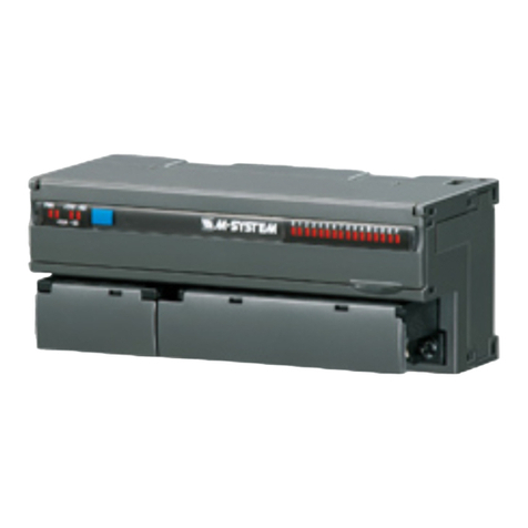
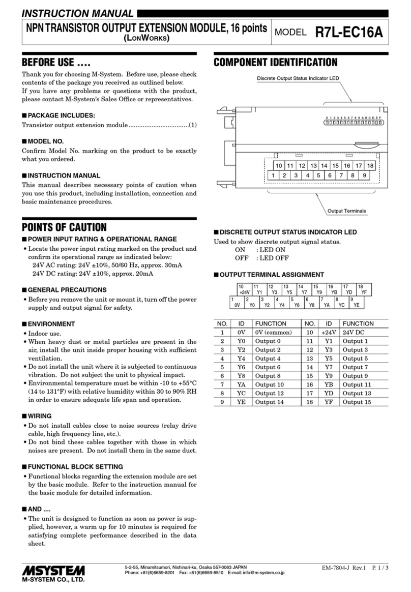
COMPONENT IDENTIFICATION
01234567
Discrete Input Status Indicator LED
Input Terminals
786910
23145
■DISCRETE INPUT STATUS INDICATOR LED
Discrete input extension modules have LED indicators
showing input signal status.
Contact ON: LED ON
Contact OFF: LED OFF
■INPUT TERMINAL ASSIGNMENT
6
NC
7
X1
8
X3
1
COM
2
X0
3
X2
9
X5
4
X4
10
X7
5
X6
NO. ID FUNCTION NO. ID FUNCTION
1 COM Common 6 NC No Connection
2 X0 Input 0 7 X1 Input 1
3 X2 Input 2 8 X3 Input 3
4 X4 Input 4 9 X5 Input 5
5 X6 Input 6 10 X7 Input 7
CONNECTING THE EXTENSION MODULE
1) Remove the extension connector cover located at the side
of the basic module.
2) Connect the extension module.
3) Mount the combined module on a DIN rail.
056 222 38 18 mailbox@sentronic.com www.sentronic.com
SENTRONIC AG
R7E-EA8
P. 2 / 2
EM-7807-N Rev.2
EXTERNAL DIMENSIONS unit: mm (inch)
11.5
(.45)
786910
23145
65 (2.56)
30 (1.18) [5 (.20)]
3 (.12)5.5 (.22)
DIN RAIL
35mm wide
54 (2.13)
17 (.66)
50 (1.97) 18.5 (.73)
10–M3 SCREW
TERMINALS
for INPUT
6 (.24)
CONNECTION DIAGRAM
Connect the unit as in the diagram below.
1
10
X7
9
X5
8
X3
7
X1
5
X6
4
X4
3
X2
2
X0
COM
EXTENSION CONNECTOR
■Input Connection Examples
1
2
10
PNP Connection
1
2
10
NPN Connection
X0
COM
–+
X7
X0
COM
–+
X7
WIRING INSTRUCTIONS
■SCREW TERMINAL
Torque: 0.5 N·m
■SOLDERLESS TERMINAL mm (inch)
Refer to the drawing below for recommended ring tongue
terminal size. Spade tongue type is also applicable. Solder-
less terminals with insulation sleeve do not fit.
Applicable wire size:
0.25 to 1.65 mm
2
(AWG 22 to 16)
Recommended manufacturer: Japan Solderless Terminal
MFG.Co.Ltd, Nichifu Co.,ltd
6 (.24) max
3.3 (.13) max
mm (inch)
056 222 38 18 mailbox@sentronic.com www.sentronic.com
SENTRONIC AG

Other M-system Control Unit manuals

M-system R3-NC1 User manual

M-system

M-system R3-NC1 User manual

M-system R7D-EC16B User manual

M-system

M-system R7D-EC16B User manual

M-system R7EWTU User manual

M-system

M-system R7EWTU User manual

M-system R3-AV4 User manual

M-system

M-system R3-AV4 User manual

M-system R5T-DA4 User manual

M-system

M-system R5T-DA4 User manual

M-system R7M-DC4G User manual

M-system

M-system R7M-DC4G User manual

M-system R7F4HML3-D-DAC32A User manual

M-system

M-system R7F4HML3-D-DAC32A User manual

M-system EtherCAT R7I4DECT-1-PA8A User manual

M-system

M-system EtherCAT R7I4DECT-1-PA8A User manual

M-system Mini-M M2MNV User manual

M-system

M-system Mini-M M2MNV User manual

M-system R7M-EC8B/UL User manual

M-system

M-system R7M-EC8B/UL User manual

M-system R3-SV8C User manual

M-system

M-system R3-SV8C User manual
M-system R3-PD16 User manual

M-system

M-system R3-PD16 User manual

M-system R8-NC3 User manual

M-system

M-system R8-NC3 User manual

M-system R7ML-DC16A User manual

M-system

M-system R7ML-DC16A User manual

M-system R7M-EA8 User manual

M-system

M-system R7M-EA8 User manual

M-system R7C-RS4 User manual

M-system

M-system R7C-RS4 User manual

M-system R7L-DA16 User manual

M-system

M-system R7L-DA16 User manual

M-system R3-NC3 User manual

M-system

M-system R3-NC3 User manual

M-system R7M-DAC16C User manual

M-system

M-system R7M-DAC16C User manual

M-system R7C-EC16A User manual

M-system

M-system R7C-EC16A User manual

M-system R7M-YV2 User manual

M-system

M-system R7M-YV2 User manual

M-system R7F4DD-DC16A-H User manual

M-system

M-system R7F4DD-DC16A-H User manual

M-system R7D-EC8A User manual

M-system

M-system R7D-EC8A User manual

M-system R30SV2 User manual

M-system

M-system R30SV2 User manual

Popular Control Unit manuals by other brands

Atheros ARS63-SB manual

Atheros

Atheros ARS63-SB manual

MADRIX Nebula Quick start guide & technical manual

MADRIX

MADRIX Nebula Quick start guide & technical manual

Flowserve NAF-Setball Maintenance and installation instructions

Flowserve

Flowserve NAF-Setball Maintenance and installation instructions

Trenz Electronic TE0720-1QFGO Schematics

Trenz Electronic

Trenz Electronic TE0720-1QFGO Schematics

Honeywell Home HM700ADVALVE installation instructions

Honeywell Home

Honeywell Home HM700ADVALVE installation instructions

Redpine Signals RS-WC-201 Integration guide

Redpine Signals

Redpine Signals RS-WC-201 Integration guide

ORTEA NEXT ICAR OUT 2N0 instructions

ORTEA NEXT

ORTEA NEXT ICAR OUT 2N0 instructions

Ideal-Standard Easybox Slim Series installation instructions

Ideal-Standard

Ideal-Standard Easybox Slim Series installation instructions

Feig Electronic ID ISC.MRMU102-A user manual

Feig Electronic

Feig Electronic ID ISC.MRMU102-A user manual

Stone STWA101WT-01 Equipment manual

Stone

Stone STWA101WT-01 Equipment manual

Linear Technology DC1872A manual

Linear Technology

Linear Technology DC1872A manual

EES MFW Series operating instructions

EES

EES MFW Series operating instructions

Honeywell SM150 installation instructions

Honeywell

Honeywell SM150 installation instructions

Pfeiffer Vacuum TPG 366 MAXIGAUGE operating instructions

Pfeiffer Vacuum

Pfeiffer Vacuum TPG 366 MAXIGAUGE operating instructions

Dometic Passport I/O Compact Operation manual

Dometic

Dometic Passport I/O Compact Operation manual

Federal Signal Corporation TM33 installation instructions

Federal Signal Corporation

Federal Signal Corporation TM33 installation instructions

Frequency Central Waverider VCDO MKii Build documentation

Frequency Central

Frequency Central Waverider VCDO MKii Build documentation

Baumann 24000CVF instruction manual

Baumann

Baumann 24000CVF instruction manual

manuals.online logo
manuals.online logoBrands
  • About & Mission
  • Contact us
  • Privacy Policy
  • Terms and Conditions

Copyright 2025 Manuals.Online. All Rights Reserved.