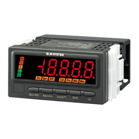
M-system 47D Series User manual

147D Series Modbus Reference Guide EM-9501-C Rev.4
47D Series Digital Panel Meters
Modbus Protocol Reference Guide
CONTENTS
1. INTRODUCTION ...................................................................................2
2. MODBUS PROTOCOL..........................................................................3
2.1 GENERAL DESCRIPTIONS ..............................................................................................3
2.2 TRANSMISSION SETTING................................................................................................3
2.3 SYSTEM CONFIGURATION EXAMPLES ..........................................................................4
2.4 MODBUS MESSAGE FRAMING........................................................................................6
2.4.1 READ HOLDING REGISTERS ...............................................................................6
2.4.2 WRITE MULTIPLE REGISTERS.............................................................................7
2.4.3 CRC CALCULATION ALGORITHM.........................................................................8
3. MODBUS REGISTERS .........................................................................9
3.1 DEVICE INFORMATION ....................................................................................................9
3.2 I/O DATA ........................................................................................................................... 10
3.3 DEVICE CONTROL.......................................................................................................... 11
3.4 LOCKOUT SETTING........................................................................................................ 11
3.5 INPUT SETTING ..............................................................................................................12
3.5.1 COMMON SETTING.............................................................................................12
3.5.2 FORCED ZERO, TARE ADJUSTMENT V M AC .................................................12
3.5.3 DC VOLTAGE/CURRENT INPUT V....................................................................13
3.5.4 POTENTIOMETER INPUT M............................................................................. 13
3.5.5 RTD INPUT R..................................................................................................... 14
3.5.6 THERMOCOUPLE INPUT T............................................................................... 14
3.5.7 AC VOLTAGE/CURRENT INPUT V.................................................................... 15
3.6 BARGRAPH SETTING..................................................................................................... 16
3.7 ANALOG OUTPUT SETTING ..........................................................................................16
3.8 ALARM SETTING............................................................................................................. 17
3.8.1 COMMON SETTING.............................................................................................17
3.8.2 SETPOINTS & BANK SWITCHING ...................................................................... 18
3.8.3 ALARM TRIP ACTION........................................................................................... 19
3.9 OPERATION CONTROL SETTING.................................................................................. 19
3.10 DISPLAY SETTING ..........................................................................................................20
3.11 MODBUS SETTING .........................................................................................................20

247D Series Modbus Reference Guide EM-9501-C Rev.4
1. INTRODUCTION
This Reference Guide explains the 47D series specications regarding Modbus protocol.
In this manual, descriptions given with the following symbols are applied only to the models those symbols are as-
signed to. Other descriptions with no specic symbol are applied to all 47D Series models.
Model No. Function Symbol
47DV DC voltage input VV
DC current input VA
DC voltage/current input V
47DT Thermocouple input T
47DR RTD input R
47DM Potentiometer input M
47DAC AC voltage input ACV
AC current input ACA
AC voltage/current input AC
Please refer to the operating manual for respective models regarding detailed functions of each parameter.

347D Series Modbus Reference Guide EM-9501-C Rev.4
2. MODBUS PROTOCOL
2.1 GENERAL DESCRIPTIONS
The 47D Series Digital Panel Meter (referred hereunder as ‘the device’) is applicable with Modbus RTU mode. ASCII
mode is not usable.
Detailed information about Modbus Protocol is described in MODBUS APPLICATION PROTOCOL V1.1a / Modbus
over Serial Line Specication & Implementation Guide V1.0, provided at Modbus-IDA (http://www.modbus.org/).
2.2 TRANSMISSION SETTING
Device address, baud rate, parity check type and other properties are selectable via the control buttons at the front
of the device. It is also possible to change these settings via Modbus communication.
COMM. PROPERTY SELECTION
Modbus address 1 to 247
Factory setting : 1
Baud rate 1200 bps
2400 bps
4800 bps
9600 bps
19200 bps
38400 bps (*)
Parity bit None
Odd (*)
Even
Stop bit 1 bit (*)
2 bits
T1.5 timer length 0.1 to 6.0, in 0.1 increments (Modbus protocol standard: 1.5)
Factory setting : 1.5
T3.5 timer length 0.1 to 6.0, in 0.1 increments (Modbus protocol standard: 3.5)
Factory setting : 3.5
Long register Normal : Low-digit word at lower address (*)
(32-bit words assignments) Swap : High-digit word at lower address
(*) Factory setting
The following parameters are xed.
COMM. PROPERTY SELECTION
Data bit 8 bits
Flow control No

447D Series Modbus Reference Guide EM-9501-C Rev.4
2.3 SYSTEM CONFIGURATION EXAMPLES
Network system congurations connecting the (slave) device to the (master) PC are as in the following examples:
CAUTION !
DO NOT attempt communication and setting at once for multiple devices. Transmissions may be mixed up and
unexpected setting changes may occur.
■RS-485 / RS-232C
Set Modbus properties as in the table below:
Modbus address Assign independent address to each device.
Baud rate Identical setting for all devices connected via the RS-232C/RS-485 Converter.
Parity bit Identical setting for all devices connected via the RS-232C/RS-485 Converter.
Stop bit Identical setting for all devices connected via the RS-232C/RS-485 Converter.
RS-485 (Modbus RTU)
RS-232-C
RS-232-C/RS-485
Converter
(model: R2K-1 or LK1)
Lightning Surge Protector
for RS-485/422
(model: MD74R or MDP-4R) *1
Lightning Surge Protector
for RS-485/422
(model: MD74R
or MDP-4R) *1
*1. Insert lightning surge protectors recommended in this example if necessary.
Digital Panel Meter
(model: 47Dx)
Max
Min
FZ
TZ
NG
Zro
Spn
TG
Hld
Tch
HH
H
P
L
LL
Max
Min
FZ
TZ
NG
Zro
Spn
TG
Hld
Tch
HH
H
P
L
LL
Max
Min
FZ
TZ
NG
Zro
Spn
TG
Hld
Tch
HH
H
P
L
LL

547D Series Modbus Reference Guide EM-9501-C Rev.4
■RS-485 / ETHERNET
Set Modbus properties as in the table below:
Modbus address Assign independent address to each device.
Baud rate 19200 bps or 38400 bps: Set identical to the 72EM2-M4.
Parity bit Odd
Stop bit 1 bit
■INFRARED PORT
Turn the device to the infrared communication mode. Modbus address is automatically xed at ‘1’ regardless of the
preset value.
Ethernet
Communication Adaptor
(model: 72EM2-M4)
ETHERNET
RUN
SEND
FIELD
CNFG
RS-485 (Modbus RTU)
Digital Panel Meter
(model: 47Dx)
Lightning Surge Protector
for RS-485/422
(model: MD74R or MDP-4R) *1
Lightning Surge Protector
for RS-485/422
(model: MD74R
or MDP-4R) *1
*1. Insert lightning surge protectors recommended in this example if necessary.
Max
Min
FZ
TZ
NG
Zro
Spn
TG
Hld
Tch
HH
H
P
L
LL
Max
Min
FZ
TZ
NG
Zro
Spn
TG
Hld
Tch
HH
H
P
L
LL
Max
Min
FZ
TZ
NG
Zro
Spn
TG
Hld
Tch
HH
H
P
L
LL
max.1 meter
Infrared Communication
Adaptor (model: COP-IRU)
Note 1: Hold down Alarm/ + Up buttons at once for 3 seconds to move on to Infrared Communication mode (IRU indicated).
Hold down Alarm/ or Scale/ button for 1 second to cancel the mode.
Analog output and Modbus functions are stopped while in this mode.
Note 2: The COP-IRU can communicate with single panel meter only. DO NOT turn more than one panel meter on to
the infrared communication mode.
Digital Panel Meter
(model: 47Dx)
Max
Min
FZ
TZ
NG
Zro
Spn
TG
Hld
Tch
HH
H
P
L
LL

647D Series Modbus Reference Guide EM-9501-C Rev.4
2.4 MODBUS MESSAGE FRAMING
The following commands are usable to communicate with the device.
FUNCTION CODE COMMAND RECOMMENDED TIME OUT VALUE
03 Read Holding Registers 0.5 second
16 Write Multiple Registers 2.0 seconds
When accessing two-word registers, it must be specied in the command to read/write two consecutive registers. If
the master sends a request to two-word registers without specifying it, the device returns Exception (error).
The lower digit word in two-word registers is assigned to the lower address (n), while the upper digit word is assigned
to the higher address (n+1). The order can be reversed by programming.
All registers are in the form of integer. Floating point or other formats are not used.
2.4.1 READ HOLDING REGISTERS
This function code is used to read the contents of a contiguous block of holding registers (measured values and set-
tings) in the remote device.
■REQUEST FORMAT
FIELD LENGTH RANGE
(1) Device address 1 byte 1 to 247
(2) Function code 1 byte 03
(3) Starting address 2 bytes 0 to 65535
Address numbered minus 1 from the register described in the
tables in Section 3.
(4) Number of registers 2 bytes 1 to 125
(5) CRC 2 bytes
■RESPONSE FORMAT
FIELD LENGTH RANGE
(1) Device address 1 byte 1 to 247
(2) Function code 1 byte 03
(3) Byte count 1 byte N x 2
N = Number of registers
(4) Register value N x 2 bytes
(5) CRC 2 bytes
■REQUEST EXAMPLE
Here is an example of a request to read 2 registers starting at the register 3 in the device address 1.
01 03 0002 0002 65CB
(1) (2) (3) (4) (5)
■RESPONSE EXAMPLE
Here is an example of a response to read ‘0009’ at the register 3, ‘0000’ at the register 4. The register 3 ranges for
two words, thus the register value shows ‘00000009.’
01 03 04 00090000 2A31
(1) (2) (3) (4) (5)
The above examples are given in hexadecimal.

747D Series Modbus Reference Guide EM-9501-C Rev.4
2.4.2 WRITE MULTIPLE REGISTERS
This function code is used to write a block of contiguous registers (settings) in the remote device.
■REQUEST FORMAT
FIELD LENGTH RANGE
(1) Device address 1 byte 1 to 247
(2) Function code 1 byte 16
(3) Starting address 2 bytes 0 to 65535
Address numbered minus 1 from the register described in the
tables in Section 3.
(4) Number of registers 2 bytes 1 to 123
(5) Byte count 1 byte N x 2
N = Number of registers
(6) Register value N x 2 bytes
(7) CRC 2 bytes
■RESPONSE FORMAT
FIELD LENGTH RANGE
(1) Device address 1 byte 1 to 247
(2) Function code 1 byte 16
(3) Starting address 2 bytes 0 to 65535
Address numbered minus 1 from the register described in the
tables in Section 3.
(4) Number of registers 2 bytes 1 to 123
(5) CRC 2 bytes
■REQUEST EXAMPLE
Here is an example of a request to write ‘6600’ (000019C8) at the 2-word register 5604 (15E3) in the device address
1.
01 10 15E3 0002 04 19C80000 C9C0
(1) (2) (3) (4) (5) (6) (7)
■RESPONSE EXAMPLE
01 10 15E3 0002 B432
(1) (2) (3) (4) (5)
The above examples are given in hexadecimal.

847D Series Modbus Reference Guide EM-9501-C Rev.4
2.4.3 CRC CALCULATION ALGORITHM
The following shows Visual Basic 6.0 sources to calculate the CRC16.
Function CRC16(Message() As Byte, Size As Integer) As Integer
Dim I As Integer, N As Integer, CarryBit As Boolean
CRC16 = &HFFFF
For I = 0 To Size - 1
CRC16 = (CRC16 And &HFF00) Or ((CRC16 And 255) Xor Message(I))
For N = 1 To 8
CarryBit = CRC16 And 1
CRC16 = ((CRC16 And &HFFFE) \ 2) And &H7FFF
If CarryBit Then CRC16 = &HA001 Xor CRC16
Next
Next
End Function
START
0xFFFF →CRC16
END
CRC16 XOR BYTE →CRC16
0 →N
Shift CRC16 by 1 LSB
Carry Over
N + 1 →N
YES
NO
NO
YES
YES
N ≥ 8
End of Message
CRC16 XOR 0xA001 →CRC16
Figures starting with 0x are hexadecimal.
NO
Following BYTE

947D Series Modbus Reference Guide EM-9501-C Rev.4
3. MODBUS REGISTERS
3.1 DEVICE INFORMATION
ADDR. WORD CONTENTS
9601 1 Device ID
Shows the device model number.
2001 : 47DV
2002 : 47DT
2003 : 47DR
2004 : 47DM
2005: 47DAC
9602 1 Extension function ag
Shows the optional functions for the hardware model as the total of the function numbers.
1 : DC output
2 : Network interface (RS-485 / Modbus RTU)
4 : Alarm output (N.O. contact x 4)
8 : Alarm output (SPDT contact x 2)
16 : DC current input V /AC current input AC
(DC or AC voltage input without this ag)
9603 1 Reserved
9604 1 Hardware version
Version number x 100
[Example] Version 1.00 = 100
9605 1 Firmware version
Version number x 100
[Example] Version 1.00 = 100
9606 8 Serial number
ASCII characters. Each character is assigned in the following order. Blank bits after the last digit of the
model number are lled with 0’s.
Offset High-order byte Low-order byte
+0 2nd character 1st character
+1 4th character 3rd character
+2 6th character 5th character
+3 8th character 7th character
+4 10th character 9th character
+5 12th character 11th character
+6 14th character 13th character
+7 16th character 15th character
9614 16 Model number (factory shipped)
ASCII characters. Each character is assigned in the following order. Blank bits after the last digit of the
model number are lled with 0’s.
Offset High-order byte Low-order byte
+0 2nd character 1st character
+1 4th character 3rd character
+2 6th character 5th character
+3 8th character 7th character
+4 10th character 9th character
+5 12th character 11th character
+6 14th character 13th character
+7 16h character 15th character
+8 18th character 17th character
+9 20th character 19th character
+10 22th character 21th character
+11 24th character 23th character
+12 26th character 25th character
+13 28th character 27th character
+14 30th character 29th character
+15 32th character 31th character
9630 2 Reserved
9632 16 Tag name
Unicode. Each character is assigned to 1 word. Master can write this register.

1047D Series Modbus Reference Guide EM-9501-C Rev.4
3.2 I/O DATA
ADDR. WORD CONTENTS
1 1 Device Error code
15Bit 14 13 12 11 10 9876543210
I.Err
W.Err
R.Err
A.Err
P.Err
Shows the following error status when the relevant bit turns ‘1.’
I.Err : E2PROM read error at the device startup
W.Err : E2PROM write error
R.Err : E2PROM read error
A.Err : ADC error
P.Err : Excitation supply output error
2 1 Device Status code
15Bit 14 13 12 11 10 9 8 7 6 5 4 3 2 1 0
LL
L
P
H
HH
S.over
S.under
Burnout
Loop Test
Analog
Shows the following device status when the relevant bit turns ‘1.’
LL, L, P, H, HH : Alarm tripped
S.over : Over-scale
S.under : Under-scale
Burnout : Burnout
Loop Test : Loop Test mode
Analog : Analog output provided
3 2 Measured value *1, *2
5 2 Measured value, MAX *1, *2
7 2 Measured value, MIN *1, *2
9 2 Reserved
11 2 Reserved
13 2 Reserved
15 2 Reserved
17 2 Reserved
19 2 Reserved
21 2 Reserved
23 2 Analog output value *2, *3
25 2 Reserved
27 2 Reserved
29 2 Reserved
31 2 Reserved
33 2 Reserved
35 2 Reserved
37 2 Reserved
39 2 Reserved
41 2 Reserved
* 1. V M AC Only normally measured signals are applied to Max and Min values. Values during scaling errors are not. Values
other than in normal measuring conditions are indenite.
*2. Display value, Max value, Min value and Analog output are indenite during the infrared communication mode.
*3. Analog output is valid only when the device status code for the analog output equals ‘1.’ It is indenite when the code equals
‘0.’

1147D Series Modbus Reference Guide EM-9501-C Rev.4
3.3 DEVICE CONTROL
ADDR. WORD CONTENTS
801 1 Bank No.
Different sets of alarm setpoints and properties (Banks) can be selected when Master writes 1 ... 8.
In order to activate this setting, Bank Switching via communication must be enabled at Register 4009.
This register is reset to ‘1’ at the device startup.
802 1 Reset MIN / MAX values
MIN / MAX reading currently on the display is reset when ‘1’ is set.
The register value is automatically reset again to ‘0’ when the MAX / MIN value resetting action is complete.
If another value is set before ‘0,’ the resetting result becomes undened.
3.4 LOCKOUT SETTING
ADDR. WORD CONTENTS
901 1 Modbus register access control
0 : Read only (*)
1 : Write enabled
This register is reset to ‘0’ at the device startup. Write ‘1’ before starting writing other registers.
Once ‘1’ is set, alarm and analog outputs are held at the last value and status before it has been turned ‘1.’
With ‘0,’ these outputs respond to the input signal.
902 1 Alarm setting lockout
0 : Completely unlock alarm settings
1 : Partially unlock alarm settings (Refer to the 47Dx operating manual for detailed information.) (*)
2 : Lock alarm settings
903 1 Scaling setting lockout
0 : Unlock scaling settings (*)
1 : Lock alarm settings
904 1 Advanced setting lockout
0 : Completely unlock advanced settings
1 : Partially advanced alarm settings (Refer to the 47Dx operating manual for detailed information.) (*)
2 : Lock advanced settings
905 1 Modbus setting lockout
0 : Lock Modbus settings
1 : Unlock Modbus settings (*)
906 1 MAX/MIN display control lockout
0 : Unlock MAX/MIN Display control (*)
1 : Lock MAX/MIN Display reset
2 : Lock MAX/MIN Display control
907 1 Forced zero control lockout V M AC
0 : Unlock Forced Zero and Tare Adjustment control (*)
1 : Unlock Forzed Zero control / Lock Tare Adjustment control
2 : Lock Forced Zero and Tare Adjustment control
908 1 Loop test output lockout
0 : Unlock Loop Test Output mode (*)
1 : Lock Loop Test Output Mode
(*): Factory setting

1247D Series Modbus Reference Guide EM-9501-C Rev.4
3.5 INPUT SETTING
3.5.1 COMMON SETTING
ADDR. WORD CONTENTS UNIT
1001 1 Averaging type
0 : Simple average
1 : Moving average (*)
1002 1 Averaging time
0 : No averaging (*)
1 : 2 samples
2 : 4 samples
3 : 8 samples
4 : 16 samples
5 : 32 samples
6 : 64 samples
7 : 128 samples
8 : 256 samples
9 : 512 samples
1003 1 High-pass lter
0 : High-pass lter OFF (*)
1 : High-pass lter ON
1011 1 Low-end cutout
0 : Low-end cutout OFF (*)
1 : Low-end cutout ON
2 : Low-end cutout by absolute value
1012 1 Low-end cutout value
0 ... 999 V M AC
Decimal point position setting
Factory setting : 0 T R °C/100 or °F/100
3.5.2 FORCED ZERO, TARE ADJUSTMENT V M AC
ADDR. WORD CONTENTS
1021 1 Forced zero
0 : Disable Forced zero (*)
1 : Enable Forced zero
2 : Enable Tare adjustment
1022 2 Force zero value
Set value : -20000 ... 100000
1024 2 Tare adjustment value
Set value : -20000 ... 100000

1347D Series Modbus Reference Guide EM-9501-C Rev.4
3.5.3 DC VOLTAGE/CURRENT INPUT V
ADDR. WORD CONTENTS
1051 1 Input type
VV 0 : 1 to 5V (*)
1 : -5 to +5V
2 : ±20V
3 : ±200V
VA 0 : 4 to 20mA (*)
1 : 0 to 20mA
2 : ±20mA
3 : ±200mA
1053 2 Input scaling value Zero
Selectable range depends upon the input type.
Input Type Selectable Range Unit
VV 1 to 5V 10000 ... 50000 V/10000
-5 to +5V -5000 ... 5000 V/1000
±20V -20000 ... 20000 V/1000
±200V -20000 ... 20000 V/100
VA 4 to 20mA 04000 ... 20000 mA/1000
0 to 20mA 00000 ... 20000 mA/1000
±20mA -20000 ... 20000 mA/1000
±200mA -20000 ... 20000 mA/100
Factory setting : VV 10000 / VA 04000
1055 2 Input scaling value Span
Refer to Input scaling value Zero for selectable ranges.
Factory setting : VV 50000 / VA 20000
1057 2 Display scaling value Zero
-20000 ... 100000
Factory setting : VV 10000 / VA 04000
1059 2 Display scaling value Span
-20000 ... 100000
Factory setting : VV 50000 / VA 20000
1061 1 Display decimal point position
Applied to the scaling values and other values set in the scaled range.
0 : 00000
1 : 0000.0
2 : 000.00
3 : 00.000
4 : 0.0000
Factory setting : VV 0.0000 / VA 00.000
3.5.4 POTENTIOMETER INPUT M
ADDR. WORD CONTENTS
1057 2 Display scaling value Zero
-20000 ... 100000
Factory setting : -10000
1059 2 Display scaling value Span
-20000 ... 100000
Factory setting : 10000
1061 1 Display decimal point position
Applied to the scaling values and other values set in the scaled range.
0 : 00000
1 : 0000.0
2 : 000.00 (*)
3 : 00.000
4 : 0.0000

1447D Series Modbus Reference Guide EM-9501-C Rev.4
3.5.5 RTD INPUT R
ADDR. WORD CONTENTS UNIT
1051 1 Input type
0 : JPt 100 (JIS ’89)
1 : Pt 100 (JIS ’89)
2 : Pt 100 (JIS ’97, IEC) (*)
3 : Pt 50 (JIS ’81)
4 : Pt 1000
1052 1 Temperature unit
0 : °C (*)
1 : °F
1063 1 Burnout
0 : Downscale
1 : Upscale (*)
1065 2 Input compensation A input value *5°C/100
-99999 ... 999999 or
Factory setting : 000 °F/100
1067 2 Input compensation B input value *5°C/100
-99999 ... 999999 or
Factory setting : 8000 °F/100
1069 2 Input compensation A compensation value °C/100
-99999 ... 999999 or
Factory setting : 0 °F/100
1071 2 Input compensation B compensation value °C/100
-99999 ... 999999 or
Factory setting : 0 °F/100
*5. Input compensation is not executed when the A and B values are equal.
3.5.6 THERMOCOUPLE INPUT T
ADDR. WORD CONTENTS UNIT
1051 1 Input type
0 : (PR)
1 : K (CA) 1 (*)
2 : K (CA) 2
3 : E (CRC)
4 : J (IC) 1
5 : J (IC) 2
6 : T (CC)
7 : B (RH)
8 : R
9 : S
10 : C (WRe5-26)
11 : N
12 : U
13 : L
1052 1 Temperature unit
0 : °C (*)
1 : °F
1063 1 Burnout
0 : Downscale
1 : Upscale (*)
1064 1 Cold junction compensation
0 : ON (*)
1 : OFF
1065 2 Input compensation A input value *5°C/100
-99999 ... 999999 or
Factory setting : 000 °F/100
1067 2 Input compensation B input value *5°C/100
-99999 ... 999999 or
Factory setting : 100000 °F/100
1069 2 Input compensation A compensation value °C/100
-99999 ... 999999 or
Factory setting : 0 °F/100
1071 2 Input compensation B compensation value °C/100
-99999 ... 999999 or
Factory setting : 0 °F/100
*5. Input compensation is not executed when the A and B values are equal.

1547D Series Modbus Reference Guide EM-9501-C Rev.4
3.5.7 AC VOLTAGE/CURRENT INPUT V
ADDR. WORD CONTENTS
1051 1 Input type
ACV 0 : 0 to 0.2V
1 : 0 to 2V
2 : 0 to 20V
3 : 0 to 200V (*)
ACA 0 : 0 to 0.2mA
1 : 0 to 2mA
2 : 0 to 20mA
3 : 0 to 200mA
1053 2 Input scaling value Zero
Selectable range depends upon the input type.
Input Type Selectable Range Unit
ACV 0 to 0.2V 000000 to 002000 V/1000
0 to 2V 000000 to 002000 V/1000
0 to 20V 000000 to 020000 V/1000
0 to 200V (*) 000000 to 020000 V/100
ACA 0 to 0.2mA 000000 to 002000 mA/1000
0 to 2mA 000000 to 002000 mA/1000
0 to 20mA 000000 to 020000 mA/1000
0 to 200mA 000000 to 020000 mA/100
Factory setting : 000000 / 000000
1055 2 Input scaling value Span
Refer to Input scaling value Zero for selectable ranges.
Factory setting : VV 50000 / VA 20000
1057 2 Display scaling value Zero
-20000 ... 100000
Factory setting : VV 10000 / VA 04000
1059 2 Display scaling value Span
-20000 ... 100000
Factory setting : VV 50000 / VA 20000
1061 1 Display decimal point position
Applied to the scaling values and other values set in the scaled range.
0 : 00000
1 : 0000.0
2 : 000.00
3 : 00.000
4 : 0.0000
Factory setting : VV 0.0000 / VA 00.000

1647D Series Modbus Reference Guide EM-9501-C Rev.4
3.6 BARGRAPH SETTING
ADDR. WORD CONTENTS
2001 1 Bargraph type
0 : No bargraph indication
1 : Unidirectional bar (*)
2 : Unidirectional bar, reverse LCD
3 : Bidirectional bar
4 : Bidirectional bar, reverse LCD
2002 2 Bargraph lower limit
-20000 ... 100000 V M AC
V M AC Decimal point position setting
-99999 ... 999999 T R T R °C/100 or °F/100
Factory setting : VV 10000 / VA 04000 / T0 / R0 / M-10000 / AC 000000/000000
2004 2 Bargraph upper limit
-20000 ... 100000 V M AC
V M AC Decimal point position setting
-99999 ... 999999 T R T R °C/100 or °F/100
Factory setting : VV 50000 / VA 20000 / T10000 / R10000 / M10000 / AC 020000/020000
3.7 ANALOG OUTPUT SETTING
ADDR. WORD CONTENTS UNIT
3001 1 Analog output type
0 : 0 to 5V
1 : -5 to +5V
2 : -10 to +10V
3 : 0 to 20mA
4 : 4 to 20mA (*)
3002 1 Analog output function mode
0 : Proportional to the display value (*)
1 : Proportional to the scaling/temperature value
3003 2 Analog output 0%
-20000 ... 100000 V M AC
V M AC Decimal point position setting
-99999 ... 999999 T R T R °C/100 or °F/100
Factory setting : VV 10000 / VA 04000 / T0 / R0 / M-10000 / AC 000000/000000
3005 2 Analog output 100%
-20000 ... 100000 V M AC
V M AC Decimal point position setting
-99999 ... 999999 T R T R °C/100 or °F/100
Factory setting : VV 50000 / VA 20000 / T10000 / R10000 / M10000 / AC 020000/020000
3007 2 Analog output 0% adjustment %/1000
-5000 ... 100000
0% adjustment value ≤ 100% adjustment value – 5000
Factory setting : 0
3009 2 Analog output 100% adjustment %/1000
0 ... 105000
0% adjustment value + 5000 ≤ 100% adjustment value
Factory setting : 100000

1747D Series Modbus Reference Guide EM-9501-C Rev.4
3.8 ALARM SETTING
3.8.1 COMMON SETTING
ADDR. WORD CONTENTS UNIT
4001 1 Manual sub display reset
0 : Alarm setpoint display is automatically reset (*)
1 : Alarm setpoint display is manually reset
4002 1 Display ashing rate at alarm conditions
0 : No ashing (*)
1 : Main display ashing in 1.0 (approx.) intervals
2 : Main display ashing in 0.5 (approx.) intervals
3 : Main display ashing in 0.3 (approx.) intervals
4003 1 Alarm output pattern
0 : Normal (*)
1 : Zone
4004 1 P output
One of LL, L, H and HH output terminals can be assigned for P.
0 : No P output (*)
1 : LL
2 : L
3 : H
4 : HH
1 (LL) and 4 (HH) are usable only with the quad alarm output option.
4005 1 Latching alarm
0 : No latching; output and measuring continued (*)
1 : Output latched / Measuring continued
2 : Output and measuring latched
4006 1 Standby sequence
0 : Output standing by until the input signal comes into P zone after the power is turned on
1 : Output is immediately provided after the power is turned on (*)
4007 1 Alarm trip at over-range
T R Burnout is handled as over-range.
0 : Alarm trip action valid at over-range (*)
1 : No alarm trip action at over-range
4008 1 Alarm power ON delay seconds/10
0 ... 9999
Factory setting : 0
4009 1 Bank switching
0 : Disabled (*)
1 : Enabled via the front button control
2 : Enabled via Modbus communication
With this register set to ‘0,’ only Bank 1 is used regardless of the settings at Register 801 or 4101.
With ‘1,’ Bank No. specied at Register 4101 is used.
With ‘2,’ Bank No. specied at Register 801 is used.
In actual applications, use Register 801 to switch Bank No. via Modbus communication by setting this register
to ‘2.’ Register 4101 is not suitable for frequent switching during operation.

1847D Series Modbus Reference Guide EM-9501-C Rev.4
3.8.2 SETPOINTS & BANK SWITCHING
Bank 1 (Register 4102 ... 4113) is used when Bank Switching is disabled.
ADDR. WORD CONTENTS UNIT
4101 1 Select Bank No.
1... 8
Factory setting : 1
4102 1 Bank 1: LL Enable
0 : Disable
1 : Enable (*)
4103 2 Bank 1: LL setpoint
-20000 ... 100000 V M AC
V M AC Decimal point position setting
-99999 ... 999999 T R T R °C/100 or °F/100
Factory setting : VV 14000 / VA 5600 / T2000 / R2000 / M-8000 / AC 2000/2000
4105 1 Bank 1: L Enable
0 : Disable
1 : Enable (*)
4106 2 Bank 1: L setpoint
-20000 ... 100000 V M AC
V M AC Decimal point position setting
-99999 ... 999999 T R T R °C/100 or °F/100
Factory setting : VV 22000 / VA 8800 / T3000 / R3000 / M-4000 / AC 6000/6000
4108 1 Bank 1: H Enable
0 : Disable
1 : Enable (*)
4109 2 Bank 1: H setpoint
-20000 ... 100000 V M AC
V M AC Decimal point position setting
-99999 ... 999999 T R T R °C/100 or °F/100
Factory setting : VV 38000 / VA 15200 / T7000 / R7000 / M4000 / AC 14000/14000
4111 1 Bank 1: HH Enable
0 : Disable
1 : Enable (*)
4112 2 Bank 1: HH setpoint
-20000 ... 100000 V M AC
V M AC Decimal point position setting
-99999 ... 999999 T R T R °C/100 or °F/100
Factory setting : VV 46000 / VA 18400 / T8000 / R8000 / M8000 / AC 18000/18000
4114 12 Bank 2 setpoints
: Identical to Bank 1 setting (4102 ... 4112)
4125
4126 12 Bank 3 setpoints
: Identical to Bank 1 setting (4102 ... 4112)
4137
4138 12 Bank 4 setpoints
: Identical to Bank 1 setting (4102 ... 4112)
4149
4150 12 Bank 5 setpoints
: Identical to Bank 1 setting (4102 ... 4112)
4161
4162 12 Bank 6 setpoints
: Identical to Bank 1 setting (4102 ... 4112)
4173
4174 12 Bank 7 setpoints
: Identical to Bank 1 setting (4102 ... 4112)
4185
4186 12 Bank 8 setpoints
: Identical to Bank 1 setting (4102 ... 4112)
4197

1947D Series Modbus Reference Guide EM-9501-C Rev.4
3.8.3 ALARM TRIP ACTION
Alarm setpoints are set at selected Bank No.s (Register 4101 ... ).
ADDR. WORD CONTENTS UNIT
4201 1 LL trip action
0 : High
1 : Low
Factory setting : 0 for HH and H, 1 for LL and L
4202 1 LL deadband (hysteresis)
0 ... 9999
V M AC Decimal point position setting
Factory setting : 1 T R °C/100 or °F/100
4203 1 LL ON delay time seconds/10
0 ... 999
Factory setting : 0
4204 1 LL OFF delay time seconds/10
0 ... 999
Factory setting : 0
4205 1 LL one-shot output time seconds/10
0 ... 9999
Factory setting : 0
4206 1 LL coil energized / de-energized at alarm trip
0 : Energized (*)
1 : De-energized
4211 6 L alarm trip action
: Identical to LL setting (4201 ... 4206)
4216
4221 6 H alarm trip action
: Identical to LL setting (4201 ... 4206)
4226
4231 6 HH alarm trip action
: Identical to LL setting (4201 ... 4206)
4236
4243 1 P ON delay time seconds/10
0 ... 999
Factory setting : 0
4244 1 P OFF delay time seconds/10
0 ... 999
Factory setting : 0
4245 1 P one-shot output time seconds/10
0 ... 9999
Factory setting : 0
4246 1 P coil energized / de-energized at alarm trip
0 : Energized (*)
1 : De-energized
3.9 OPERATION CONTROL SETTING
ADDR. WORD CONTENTS
5001 1 Automatic return time to the measuring mode
The displays can be automatically returned to the normal operation when the preset time period has been
elapsed after the last front button control.
0 : Manual returning only
1 ... 99 : Seconds
Factory setting : 15
5002 1 Transition time to the lockout control mode
The displays can be switched to Lockout Control Mode when the designated buttons are held down for a
preset time period.
0 ... 99 : Seconds
Factory setting : 5

2047D Series Modbus Reference Guide EM-9501-C Rev.4
3.10 DISPLAY SETTING
ADDR. WORD CONTENTS UNIT
6001 1 Display color
0 : Green (normal) to Red (alarm) (*)
1 : Green
2 : Red (normal) to Green (alarm)
3 : Red
6002 1 Decimal fractions for temperature input T R
0 : No fractions
1 : 1 decimal place (*)
2 : 2 decimal places R(°C only)
6003 1 Round off low-digit reading
0 : 1 (*)
1 : 2
2 : 5
3 : 10
6004 1 Display refreshing rate seconds/10
0 : Fastest possible (50 msec) (*)
1 ... 999 : Seconds
6005 1 Display reading type
0 : Measured value (*)
1 : Maximum value
2 : Minimun value
6006 1 Backlight brightness
1 (dark) ... 3 (bright)
Factory setting : 2
6007 1 LCD Contrast
1 (low) ... 10 (high)
Factory setting : 5
3.11 MODBUS SETTING
Modbus setting is enabled only after the device has been reset or the power supply has been turned off and on.
ADDR. WORD CONTENTS
7001 1 Device address
1 ... 247
Factory setting : 1
7002 1 Baud rate
0 : 1200 bps
1 : 2400 bps
2 : 4800 bps
3 : 9600 bps
4 : 19200 bps
5 : 38400 bps (*)
7003 1 Parity bit
0 : None
1 : Odd (*)
2 : Even
7004 1 Stop bit
0 : 1 bit (*)
1 : 2 bits
7005 1 T1.5 timer
1 ... 60 (character length x10)
Factory setting : 15
7006 1 T3.5 timer
1 ... 60 (character length x10)
Factory setting : 35
7007 1 Long register
0 : Normal, Low-digit word at the lower address (*)
1 : Swap, High-digit word at the lower address
Table of contents
Other M-system Measuring Instrument manuals

M-system
M-system R7CWTU User manual

M-system
M-system KSE-x1 User manual

M-system
M-system 47DV User manual

M-system
M-system AS4M User manual

M-system
M-system 47 Series User manual

M-system
M-system 47LPT User manual

M-system
M-system 71VR1 User manual

M-system
M-system R1M-P4 User manual

M-system
M-system 47DV User manual

M-system
M-system JPSM User manual

M-system
M-system 71VR1 User manual

M-system
M-system 40LV User manual

M-system
M-system TR30 User manual

M-system
M-system R1M-J3 User manual

M-system
M-system 48NAVA User manual

M-system
M-system R9WTU-ED User manual

M-system
M-system 48NV User manual

M-system
M-system R1MS-GH3 User manual

M-system
M-system 47DV User manual

M-system
M-system JB2 User manual