manuals.online logo
Brands
  1. Home
  2. •
  3. Brands
  4. •
  5. M-system
  6. •
  7. Measuring Instrument
  8. •
  9. M-system 47NL Series User manual

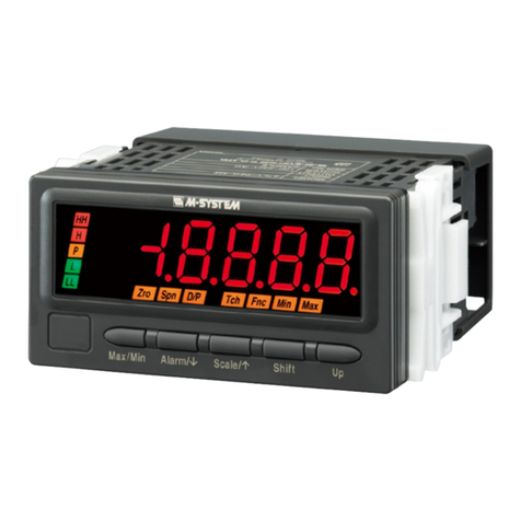
M-system 47NL Series User manual

This manual suits for next models

1

Other M-system Measuring Instrument manuals

M-system 47DAC User manual

M-system

M-system 47DAC User manual

M-system 71VR1 User manual

M-system

M-system 71VR1 User manual

M-system 47DV User manual

M-system

M-system 47DV User manual

M-system 47LCT User manual

M-system

M-system 47LCT User manual

M-system 47 Series User manual

M-system

M-system 47 Series User manual

M-system JB2 User manual

M-system

M-system JB2 User manual

M-system 47D Series User manual

M-system

M-system 47D Series User manual

M-system TR30 User manual

M-system

M-system TR30 User manual

M-system 47 Series User manual

M-system

M-system 47 Series User manual

M-system 47LPT User manual

M-system

M-system 47LPT User manual

M-system 47LV User manual

M-system

M-system 47LV User manual

M-system M Series User manual

M-system

M-system M Series User manual

M-system 48NAVA User manual

M-system

M-system 48NAVA User manual

M-system R9MWTU User manual

M-system

M-system R9MWTU User manual

M-system R10-BS1 User manual

M-system

M-system R10-BS1 User manual

M-system 73VR21 Series User manual

M-system

M-system 73VR21 Series User manual

M-system R9WTU-ED User manual

M-system

M-system R9WTU-ED User manual

M-system R1M-P4 User manual

M-system

M-system R1M-P4 User manual

M-system AS4M User manual

M-system

M-system AS4M User manual

M-system 48NAR User manual

M-system

M-system 48NAR User manual

M-system 47 Series User manual

M-system

M-system 47 Series User manual

M-system 47LCT User manual

M-system

M-system 47LCT User manual

M-system JPSM User manual

M-system

M-system JPSM User manual

M-system 73VR1100 User guide

M-system

M-system 73VR1100 User guide

Popular Measuring Instrument manuals by other brands

Powerfix Profi 278296 Operation and safety notes

Powerfix Profi

Powerfix Profi 278296 Operation and safety notes

Test Equipment Depot GVT-427B user manual

Test Equipment Depot

Test Equipment Depot GVT-427B user manual

Fieldpiece ACH Operator's manual

Fieldpiece

Fieldpiece ACH Operator's manual

FLYSURFER VIRON3 user manual

FLYSURFER

FLYSURFER VIRON3 user manual

GMW TG uni 1 operating manual

GMW

GMW TG uni 1 operating manual

Downeaster Wind & Weather Medallion Series instruction manual

Downeaster

Downeaster Wind & Weather Medallion Series instruction manual

Hanna Instruments HI96725C instruction manual

Hanna Instruments

Hanna Instruments HI96725C instruction manual

Nokeval KMR260 quick guide

Nokeval

Nokeval KMR260 quick guide

HOKUYO AUTOMATIC UBG-05LN instruction manual

HOKUYO AUTOMATIC

HOKUYO AUTOMATIC UBG-05LN instruction manual

Fluke 96000 Series Operator's manual

Fluke

Fluke 96000 Series Operator's manual

Test Products International SP565 user manual

Test Products International

Test Products International SP565 user manual

General Sleep Zmachine Insight+ DT-200 Service manual

General Sleep

General Sleep Zmachine Insight+ DT-200 Service manual

Sensa Core Lacto Spark user manual

Sensa Core

Sensa Core Lacto Spark user manual

VOLTCRAFT UTS-1980 operating instructions

VOLTCRAFT

VOLTCRAFT UTS-1980 operating instructions

EBCHQ 94915 Operation manual

EBCHQ

EBCHQ 94915 Operation manual

Balluff BIP LD2-T017-01-EP-S4 Series user guide

Balluff

Balluff BIP LD2-T017-01-EP-S4 Series user guide

Pulsar IMP Lite Series instruction manual

Pulsar

Pulsar IMP Lite Series instruction manual

ETCR 6800 user manual

ETCR

ETCR 6800 user manual

manuals.online logo
manuals.online logoBrands
  • About & Mission
  • Contact us
  • Privacy Policy
  • Terms and Conditions

Copyright 2025 Manuals.Online. All Rights Reserved.

MODEL: 47NLN
47NLN SPECIFICATIONS ES-9563 Rev.4 Page 1/4
https://www.m-system.co.jp/
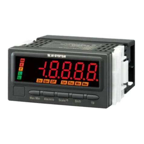
Digital Panel Meters 47NL Series
LOOP POWERED DIGITAL PANEL METER
(4 1/2 digit, LED display type)
Functions & Features
• 4 ½ digit loop powered digital panel meter
• No external power source needed
• Moving average function to suppress the display flickering
• Scaling, forced zero, low-end cutout
• Max. and Min. value display
Zro Spn D/P
Tch Fnc Min Max
Scale/
Max/Min Shift Up
96.0 (3.78)
48.0
(1.89)
20.0 (.79)
mm (inch)
MODEL: 47NLN-[1][2]
ORDERING INFORMATION
• Code number: 47NLN-[1][2]
Specify a code from below for each of [1] and [2].
(e.g. 47NLN-R/Q)
• Specify the specification for option code /Q
(e.g. /SET)
INPUT
Current
4 – 20 mA DC
[1] DISPLAY COLOR
R: Red
G: Green
[2] OPTIONS
blank: none
/Q: With options (specify the specification)
SPECIFICATIONS OF OPTION: Q
EX-FACTORY SETTING
/SET: Preset according to the Ordering Information Sheet
(No. ESU-9563)
GENERAL SPECIFICATIONS
Construction: Panel mount type
Degree of protection: IP66; Applicable to the front of the
panel meter mounted according to the specified panel
cutout. Only screw mounting conforms.
Connection: Screwless spring terminal
Applicable wire size: 0.2 to 0.5 mm2, stripped length 6 mm
Housing material: Flame-resistant resin (gray)
Setting: (Front button)
• Scaled range
• Moving average
• Others
(Refer to the instruction manual for details)
Averaging: None or moving average
Lockout setting: Prohibiting certain operations; protecting
settings
DISPLAY
Display: 16 mm (.63) high, 4 ½ digits, 7-segment LED
Display range: -19999 to 19999
Decimal point position: 10–1, 10–2, 10–3, 10–4 or none
Zero indication: Higher-digit zeros are suppressed.
Over-range indication: ‘-19999’ or ‘19999’ blinking for
display values out of the display range.
‘S.ERR’ and ‘Min’ or ‘Max’ blinking when the input signal is
out of the usable range.
Function indicators:
Zro, Spn, D/P, Tch, Fnc, Min, Max
Display mode status and operation status, ON or blink
(Display color is the same as display color code.)
Engineering unit indication: Sticker label attached
DC, AC, mV, V, kV, μA, mA, A, kA, mW, W,
kW, var, kvar, Mvar, VA, Hz, Ω, kΩ, MΩ,
cm, mm, m, m/sec, mm/min, cm/min, m/min,
m/h, m/s2, inch, ℓ, ℓ/s, ℓ/min, ℓ/h, m3, m3/sec,
m3/min, m3/h, Nm3/h, N·m, N/m2, g, kg, kg/h,
N, kN, Pa, kPa, MPa, t, t/h, ℃, °F, %RH, J,
kJ, MJ, rpm, sec, min, pH, %, ppm, etc.
INPUT SPECIFICATIONS
■ DC Current
Current range: Approx. 3.7 to 23 mA DC
Voltage drop: Approx. 6.3 V with 4 mA; approx. 6.5 V with
20 mA (Equivalent input impedance: Approx. 325 Ω)
(There is voltage drop generated by using the unit. For the
two-wire transmitter power supply, make sure that the
operable voltage for the two-wire transmitter is ensured
including the voltage drop by other devices and wiring
resistance.)

MODEL: 47NLN
47NLN SPECIFICATIONS ES-9563 Rev.4 Page 2/4
https://www.m-system.co.jp/
INSTALLATION
Operating temperature: -10 to +55°C (14 to 131°F)
Operating humidity: 10 to 90 %RH (non-condensing)
Mounting: Magnet or screw mounting
Weight: 75 g (2.6 oz)
PERFORMANCE
Accuracy
Display: ±0.1 % ± 1 digit
Temp. coefficient: ±0.015 %/°C (±0.008 %/°F)
STANDARDS & APPROVALS
EU conformity:
EMC Directive
EMI EN 61000-6-4
EMS EN 61000-6-2
RoHS Directive
EXTERNAL VIEW
Max
/
Min Scale
/
Shift Up
D
/
PSpnZro Tch MaxMinFnc
(1) Main Display
(2) Function Indicators
(3) Max/Min Button
(4) Button
(7) Up Button
(6) Shift Button
(5) Scale/ Button
■COMPONENT IDENTIFICATION
No. COMPONENT FUNCTION
(1) Main display Indicates present values, setting values and status of the unit.
(2) Function indicators Indicates the status in each setting mode.
(3) Max/Min button Used to switch the main display to show the present values, maximum values or minimum values.
(4)
Button Used to shift through setting items in each setting mode etc.
(5) Scale/ button Used to move on to the scaling setting and other setting modes; or to shift through setting items in each set-
ting mode.
(6) Shift button Used to move on to the setting standby status of each setting mode or to shift through display digits in each
setting item.
(7) Up button Used to change setting values, to execute/cancel Forced Zero or to select setting values.
Note: Refer to the operating manual for details on each function.
MODEL: 47NLN
47NLN SPECIFICATIONS ES-9563 Rev.4 Page 3/4
https://www.m-system.co.jp/
EXTERNAL DIMENSIONS & TERMINAL ASSIGNMENTS unit: mm (inch)
96.0 (3.78)
48.0 (1.89)
20.0(.79)
■FRONT VIEW
■REAR VIEW
■SIDE VIEW
• SCREW MOUNTING • MAGNET MOUNTING
Watertight packing
20.0(.79)
Magnet label sheet
4
-
M4 SCREW 8.0 (.31)
deep
1 2 3 4 5 6 7 8
MOUNTING REQUIREMENTS unit: mm (inch)
■PANEL MOUNTING
 (Conform to degree of protection IP66)
Panel cutout must be such as M-System specified. Use
watertight packing and unit fixing screws included in the
product package.
42.25 (1.66) 42.25 (1.66)
4-4.5 (.18) dia.
20.5
(.81)
17
(.67)
30.5 (1.20) dia.
• Single Mounting unit: mm (inch)
■MAGNET MOUNTING
 (Not conform to degree of protection IP66)
Panel cutout is not required. Use magnet sheet and stopper
included in the product package.
• Clustered Mounting unit: mm (inch)
96.0 (3.78)
48.0 (1.89)
min. 120 (4.72)
min. 100 (3.94)
min.120 (4.72)
min. 75 (2.95)
Panel thickness: 1.0 to 3.2 mm
MODEL: 47NLN
47NLN SPECIFICATIONS ES-9563 Rev.4 Page 4/4
https://www.m-system.co.jp/
SCHEMATIC CIRCUITRY & CONNECTION DIAGRAM
+
–2
1
INPUT
+
–
Two-wire Transmitter
Power Source
Digital
Computation
A/D
Converter
Display /
Setting
3
4
5
6
7
8
Controllor, etc.
4 – 20mA DC
2
1
+
INPUT
■ 4-WIRE CONNECTION EXAMPLE
++
––
–
I/P Positioner, etc.
Specifications are subject to change without notice.