JB2
5-2-55, Minamitsumori, Nishinari-ku, Osaka 557-0063 JAPAN
Phone: +81(6)6659-8201 Fax: +81(6)6659-8510 E-mail: info@m-system.co.jp
EM-2642 Rev.3 P. 3 / 5
FRONT VIEW & PROGRAMMING
Please refer to the Operation Manual for Model PU-2x (EM-9255), Section A: (A-1) Introduction, (A-2) General Operation
Description, (A-3) General Operation Flow Chart for general information.
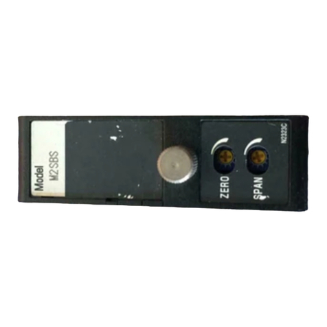
Front Cover (open)
Span Adj.
Zero Adj.
RUN Output LED
MAN. Status LED
UP Command LED
DOWN Command LED
MAN. Command LED
Modular Jack
• PROGRAMMING WITH PU-2x
G
ITEM No.
I()
D
Response MessagesGROUP No.
Data to be entered
or Messages
LCD Display
• Response Messages
OK: OK
NG: No good. Check modular jack connection.
ER: Communication error
[GROUP 01]
ITEM MDFY. DATA INPUT DISPLAY CONTENTS
01 S MAINTENANCE SWITCH
0 MTSW : MON.MODE 0: Data indication only.
1 MTSW : PRG.MODE 1: All ‘P’ marked parameters are modifiable. *1
02 P Alphabets & No. TG : XXXXXXXXXX Tag name entry (10 characters max.)
03 D No input OUTPER : XXX.XX Output in %
04 D No input OUTVAL : XX.XXX Output value in mA
05 D No input INPPER : XXX.XX Input in %
06 D No input INPVAL : XX.XXX Input value in mA
10 P WRITE DEFAULT Initializing all setting values to the factory standard ones.
ENTR COMPLETED Initialization complete
21 P Manual control mode (factory set value: 1)
Specifies the initial MV output value when starting MAN control
1 1 : DIRECT CAS control signal value
2 2 : TRACE BACK CAS control signal value going back for ITEM 28 set time period
3 3 : FIXED VALUE Fixed value set in ITEM 29
22 P Numeric SLDBAK : XXX.XX MAN/CAS transition response (%/second)
Selectable range: 0.00 to 200.00
No sliding-back function with 0.00
23 P UP/DOWN response mode (factory set value: 0)
0 0 : UNIFORM Constant ramp rate while the key is held down.
1 1 : ONE+UNIFORM Normal response rate for once when the key is pressed.
Constant ramp rate if it is continuously held down.
22 : ACCELERATED Accelerated response when the key is pressed until it reaches the
constant ramp rate.
24 P Numeric KEYRES : XXX.XX UP/DOWN response time (ramp rate) (%/second)
Selectable range: 0.00 to 200.00 (factory set value: 10.00)
25 P High/Low alarm mode at CAS control (factory set value: 0)
0 0 : NO ALARM No alarm trip
1 1 : LOW ALARM Low alarm trip only
2 2 : HIG ALARM High alarm trip only
33 : ALL ALARM High/Low alarm trip
26 P Numeric ALMLOW : XXX.XX CAS input Low alarm setpoint (%)
Selectable range: -25.00 to 125.00 (factory set value: -25.00)
27 P Numeric ALMHIG : XXX.XX CAS input High alarm setpoint (%)
Selectable range: -25.00 to 125.00 (factory set value: 125.00)
28 P Numeric TRACEBACK : XX.X Retroactive time period (seconds)
Selectable range: 0.0 to 10.0 (factory set value: 0.0)
29 P Numeric MANFIX : XXX.XX Initial manual control value (%)
Selectable range: -25.00 to 125.00 (factory set value: 0.00)
30 P Numeric PWRFIX : XXX.XX Output in % after power on in manual control mode
Selectable range: -25.00 to 125.00 (factory set value: -25.00)
31 P Output value after power on
(see “JB2 Actions when the Power Supply is Recovered after Failure.”)
00: HOLD VALUE The value stored at the moment of power failure
11: FIXED VALUE The value preset in the ITEM 30
32 D No input NVRWRCNT: XXX Number of rewriting E2PROM (32-bit)
Count when changing program or power off
