manuals.online logo
Brands
  1. Home
  2. •
  3. Brands
  4. •
  5. M-system
  6. •
  7. Measuring Instrument
  8. •
  9. M-system R7K4GUS-G16D4 User manual

M-system R7K4GUS-G16D4 User manual

5-2-55, Minamitsumori, Nishinari-ku, Osaka 557-0063 JAPAN
Phone: +81(6)6659-8201 Fax: +81(6)6659-8510 E-mail: info@m-system.co.jp
EM-7765-A P. 1 / 4
INSTRUCTION MANUAL
BEFORE USE ....
Thank you for choosing M-System. Before use, please check
contents of the package you received as outlined below.
If you have any problems or questions with the product,
please contact M-System’s Sales Office or representatives.
This equipment is for use in general industrial environ-
ments, therefore may not be suitable for applications which
require higher level of safety (e.g. safety or accident preven-
tion systems) or of reliability (e.g. vehicle control or combus-
tion control systems).
For safety, installation and maintenance of this equipment
must be conducted by qualified personnel.
■PACKAGE INCLUDES:
PC recorder..........................................................................(1)
■MODEL NO.
Confirm Model No. marking on the product to be exactly
what you ordered.
■INSTRUCTION MANUAL
This manual describes necessary points of caution when
you use this product, including installation, connection and
basic maintenance procedures.
POINTS OF CAUTION
■CONFORMITY WITH EU DIRECTIVES
• The equipment must be mounted inside the instrument
panel of a metal enclosure.
• The actual installation environments such as panel con-
figurations, connected devices, connected wires, may affect
the protection level of this unit when it is integrated in a
panel system. The user may have to review the CE re-
quirements in regard to the whole system and employ ad-
ditional protective measures* to ensure the CE conformity.
* For example, installation of noise filters and clamp fil-
ters for the power source, input and output connected
to the unit, etc.
■POWER INPUT RATING & OPERATIONAL RANGE
• Locate the power input rating marked on the product and
confirm its operational range as indicated below:
5 V DC power input by USB bus powered: ≤ 120 mA
• The R7K4GUS-G16D4 is a high power device supplied
through the USB port.
• The USB high power port must be capable of 500 mA
power consumption. When connecting the R7K4GUS-
G16D4 to a USB hub, choose the self-powered configura-
tion. Laptop PC’s supply current may be limited by its
battery power.
• Confirm the USB port’s current capacity in advance.
■GENERAL PRECAUTIONS
• Before you remove the unit or mount it, turn off the power
supply and I/O signal for safety.
■ENVIRONMENT
• Indoor use.
• When heavy dust or metal particles are present in the
air, install the unit inside proper housing with sufficient
ventilation.
• Do not install the unit where it is subjected to continuous
vibration. Do not subject the unit to physical impact.
• Environmental temperature must be within -10 to +55°C
(14 to 131°F) with relative humidity within 30 to 90% RH
in order to ensure adequate life span and operation.
• Be sure that the ventilation slits are not covered with ca-
bles, etc.
■WIRING
• Wrong connection may damage the module.
• Do not pull cables tightly.
• Do not install cables close to noise sources (relay drive
cable, high frequency line, etc.).
• Do not bind these cables together with those in which
noises are present. Do not install them in the same duct.
■CONNECTING/DISCONNECTING TO THE PC
• Do not connect/disconnect the R7K4GUS-G16D4 while
the PC Recorder software program is running (when the
screen is not in pause).
• Wait that RUN LED turns on before starting recording.
■USB HUB
• In certain system configurations using a USB hub/switch,
there are possibilities of missing sampling due to delays
at the hub. We recommend to limit the number of con-
nected devices to the minimum if a hub must be used.
■AND ....
• The unit is designed to function as soon as power is sup-
plied, however, a warm up for 10 minutes is required for
satisfying complete performance described in the data
sheet.
PC RECORDER
(Bus powered USB, 16 points DC input, 2 points PNP discrete
input, 2 points photo MOSFET relay output, tension clamp terminal)
MODEL
R7K4GUS-G16D4
R7K4GUS-G16D4
5-2-55, Minamitsumori, Nishinari-ku, Osaka 557-0063 JAPAN
Phone: +81(6)6659-8201 Fax: +81(6)6659-8510 E-mail: info@m-system.co.jp
EM-7765-A P. 2 / 4
COMPONENT IDENTIFICATION
USBConnectorfor
PowerSupplyandCommunication
(USBType-C) Status Indicator LED Discrete I/O Status Indicator LED
I/O Terminals
■STATUS INDICATOR LED
ID S TAT U S COLOR FUNCTION
PWR ON Green The power is supplied
OFF – No power is supplied.
RUN ON Green Communicating
OFF – No communication
■DISCRETE I/O STATUS INDICATOR LED
LED green indicators shows the signal status.
ON : LED ON
OFF : LED OFF
■POWER SUPPLY, I/O TERMINAL ASSIGNMENT
8 7 65 4 3 2 1
Unit side connector: PTSM0,5/8-2,5-V SMD R44 (Phoenix Contact)
Applicable wire size: 0.25 - 0.34mm2
Stripped length: 6mm
Recommended solderless terminal
AI0,25-6BU 0.25mm2(Phoenix Contact)
AI0,25-6YE 0.25mm2(Phoenix Contact)
AI0,34-6TQ 0.34mm2(Phoenix Contact)
· DISCRETE I/O
PIN
NO. ID FUNCTION
1 DO2 Photo MOSFET output 2
2 DO2 Photo MOSFET output 2
3 DO1 Photo MOSFET output 1
4 DO1 Photo MOSFET output 1
5
-
Unused
6 DI2 Discrete input 2
7 DI1 Discrete input 1
8 COM Common
·
ANALOG INPUT
PIN
NO. ID FUNCTION PIN
NO. ID FUNCTION PIN
NO. ID FUNCTION PIN
NO. ID FUNCTION
1 AI4
-
Input 4
-
1 AI8
-
Input 8
-
1 AI12
-
Input 12
-
1 AI16
-
Input 16
-
2 AI4+ Input 4+ 2 AI8+ Input 8+ 2 AI12+ Input 12+2AI16+ Input 16+
3 AI3
-
Input 3
-
3 AI7
-
Input 7
-
3 AI11
-
Input 11
-
3 AI15
-
Input 15
-
4 AI3+ Input 3+ 4 AI7+ Input 7+ 4 AI11+ Input 11+4AI15+ Input 15+
5 AI2
-
Input 2
-
5 AI6
-
Input 6
-
5 AI10
-
Input 10
-
5 AI14
-
Input 14
-
6 AI2+ Input 2+ 6 AI6+ Input 6+ 6 AI10+ Input 10+6AI14+ Input 14+
7 AI1
-
Input 1
-
7 AI5
-
Input 5
-
7 AI9
-
Input 9
-
7 AI13
-
Input 13
-
8 AI1+ Input 1+ 8 AI5+ Input 5+ 8 AI9+ Input 9+ 8 AI13+ Input 13+
R7K4GUS-G16D4
5-2-55, Minamitsumori, Nishinari-ku, Osaka 557-0063 JAPAN
Phone: +81(6)6659-8201 Fax: +81(6)6659-8510 E-mail: info@m-system.co.jp
EM-7765-A P. 3 / 4
MOUNTING INSTRUCTIONS
■DIN RAIL MOUNTING
• Mounting
1) Set the upper hook at the rear side of the unit on the DIN
rail.
2) Push in the lower.
1
2
• Dismounting
1) Push down the DIN rail mounter slider with tip of a mi-
nus screwdriver.
2) Pull the lower of the unit.
3) Remove the upper hook of the unit from the DIN rail.
1
1
2
3
■SURFACE MOUNTING
(unit: mm [inch])
Torque: 1.4 N∙m
2-M4
201 [7.91]
43 [1.69]
TERMINAL CONNECTIONS
Connect the unit as in the diagram below.
■EXTERNAL DIMENSIONS unit: mm [inch]
210 [8.27] DIN rail
(35 mm wide)
50 [1.97]
55 [2.17]
(4 [.16])
50 [1.97]
3.5 [.14]5 [.20]
R7K4GUS-G16D4
5-2-55, Minamitsumori, Nishinari-ku, Osaka 557-0063 JAPAN
Phone: +81(6)6659-8201 Fax: +81(6)6659-8510 E-mail: info@m-system.co.jp
EM-7765-A P. 4 / 4
■CONNECTION DIAGRAM
6
8
5
7
4
3
2
1
AI1
-
+
AI2
-
+
AI3
-
+
AI4
-
+
6
8
5
7
4
3
2
1
AI5
-
+
AI6
-
+
AI7
-
+
AI8
-
+
6
8
5
7
4
3
2
1
AI9
-
+
AI10
-
+
AI11
-
+
AI12
-
+
6
8
5
7
4
3
2
1
AI13
-
+
AI14
-
+
AI15
-
+
AI16
-
+
6
8
5
7
4
3
2
1
USB
Connector
DI1
COM
NC
DI2
DO1
DO2
Power supply 0V
5V
Communication
■Relay protection
· AC Powered
1
2
Inductive
Load (Coil)
Inductive
Load (Relay)
· DC Powered
1
2LOAD
Diode, Varistor or
CR Circuit
LOAD
U
Varistor or
CR Circuit

Other M-system Measuring Instrument manuals

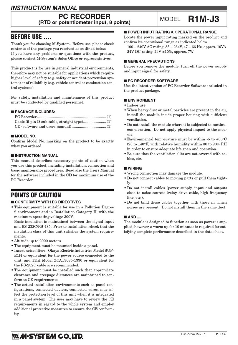
M-system AS4M User manual

M-system

M-system AS4M User manual

M-system R9EWTU User manual

M-system

M-system R9EWTU User manual

M-system KADS User manual

M-system

M-system KADS User manual

M-system 47DAC User manual

M-system

M-system 47DAC User manual

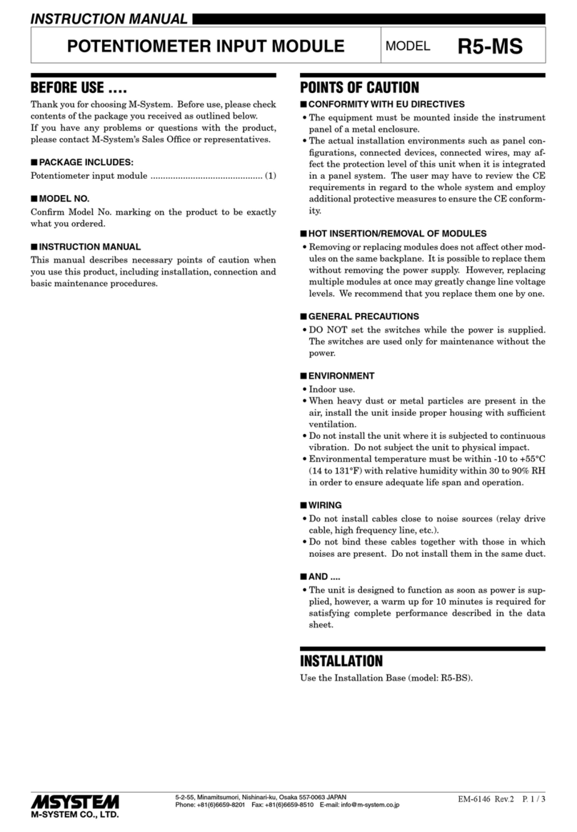
M-system R5-MS User manual

M-system

M-system R5-MS User manual

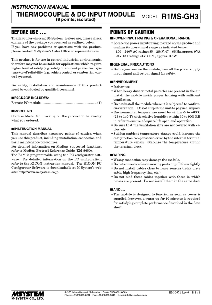
M-system R1MS-GH3 User manual

M-system

M-system R1MS-GH3 User manual

M-system 47 Series User manual

M-system

M-system 47 Series User manual

M-system 48NV User manual

M-system

M-system 48NV User manual

M-system 47 Series User manual

M-system

M-system 47 Series User manual

M-system R9WTU-ED User manual

M-system

M-system R9WTU-ED User manual

M-system R9MWTU User manual

M-system

M-system R9MWTU User manual

M-system 47 Series User manual

M-system

M-system 47 Series User manual

M-system 48NAV User manual

M-system

M-system 48NAV User manual

M-system KSE-x1 User manual

M-system

M-system KSE-x1 User manual

M-system 47LPA User manual

M-system

M-system 47LPA User manual

M-system 47LHZ User manual

M-system

M-system 47LHZ User manual

M-system 48NAR User manual

M-system

M-system 48NAR User manual

M-system 47D Series User manual

M-system

M-system 47D Series User manual

M-system 47 Series User manual

M-system

M-system 47 Series User manual

M-system 71VR1 User manual

M-system

M-system 71VR1 User manual

M-system TR30 User manual

M-system

M-system TR30 User manual

M-system 47LV User manual

M-system

M-system 47LV User manual

M-system 47NL Series User manual

M-system

M-system 47NL Series User manual

M-system 47DT User manual

M-system

M-system 47DT User manual

Popular Measuring Instrument manuals by other brands

AlphaLab GM1-HS instructions

AlphaLab

AlphaLab GM1-HS instructions

Hanna Instruments HI 993310 instruction manual

Hanna Instruments

Hanna Instruments HI 993310 instruction manual

Campbell 05103 instruction manual

Campbell

Campbell 05103 instruction manual

Saker XFVP user manual

Saker

Saker XFVP user manual

Anritsu Site Master S311D user guide

Anritsu

Anritsu Site Master S311D user guide

FineTek ECP1 Operation manual

FineTek

FineTek ECP1 Operation manual

Beha-Amprobe Telaris Series user manual

Beha-Amprobe

Beha-Amprobe Telaris Series user manual

Hanna Instruments HI 761 quick start guide

Hanna Instruments

Hanna Instruments HI 761 quick start guide

Polytec PDV-100 user manual

Polytec

Polytec PDV-100 user manual

Konica Minolta CM3600D brochure

Konica Minolta

Konica Minolta CM3600D brochure

inbody InBody570 user manual

inbody

inbody InBody570 user manual

Ametek WDG-V UOP user manual

Ametek

Ametek WDG-V UOP user manual

Bently Nevada 3300/01 Series Operation manual

Bently Nevada

Bently Nevada 3300/01 Series Operation manual

Greenlee CLM-1000 instruction manual

Greenlee

Greenlee CLM-1000 instruction manual

ATP Instrumentation MT-913 user manual

ATP Instrumentation

ATP Instrumentation MT-913 user manual

EasySplicer PRO user manual

EasySplicer

EasySplicer PRO user manual

Spectrum Fieldscout 2265FS product manual

Spectrum

Spectrum Fieldscout 2265FS product manual

Sealey TM105 instructions

Sealey

Sealey TM105 instructions

manuals.online logo
manuals.online logoBrands
  • About & Mission
  • Contact us
  • Privacy Policy
  • Terms and Conditions

Copyright 2025 Manuals.Online. All Rights Reserved.