manuals.online logo
Brands
  1. Home
  2. •
  3. Brands
  4. •
  5. M-system
  6. •
  7. Measuring Instrument
  8. •
  9. M-system R10-BS1 User manual

M-system R10-BS1 User manual

5-2-55, Minamitsumori, Nishinari-ku, Osaka 557-0063 JAPAN
Phone: +81(6)6659-8201 Fax: +81(6)6659-8510 E-mail: info@m-system.co.jp
EM-6248 P. 1 / 4
INSTRUCTION MANUAL
INSTALLATION BASE MODEL R10-BS1
BEFORE USE ....
Thank you for choosing M-System. Before use, please check
contents of the package you received as outlined below.
If you have any problems or questions with the product,
please contact M-System’s Sales Office or representatives.
■PACKAGE INCLUDES:
Installation base..................................................................(1)
■MODEL NO.
Confirm Model No. marking on the product to be exactly
what you ordered.
■INSTRUCTION MANUAL
This manual describes necessary points of caution when
you use this product, including installation, connection and
basic maintenance procedures.
POINTS OF CAUTION
■CONFORMITY WITH EU DIRECTIVES
• The equipment must be mounted inside the instrument
panel of a metal enclosure.
• The actual installation environments such as panel con-
figurations, connected devices, connected wires, may af-
fect the protection level of this unit when it is integrated
in a panel system. The user may have to review the CE
requirements in regard to the whole system and employ
additional protective measures to ensure the CE conform-
ity.
■GENERAL PRECAUTIONS
• Before you remove the unit or mount it, turn off the power
supply, input and output signals for safety.
■ENVIRONMENT
• Indoor use.
• When heavy dust or metal particles are present in the
air, install the unit inside proper housing with sufficient
ventilation.
• Do not install the unit where it is subjected to continuous
vibration. Do not subject the unit to physical impact.
• Environmental temperature must be within -10 to +55°C
(14 to 131°F) with relative humidity within 10 to90% RH
in order to ensure adequate life span and operation.
■WIRING
• Do not install cables close to noise sources (relay drive
cable, high frequency line, etc.).
• Do not bind these cables together with those in which
noises are present. Do not install them in the same duct.
INSTALLATION
Slider
Specification
(side)
Slider
MountingUnitCursorKey
MountingUnitLockSlot
1
6
10
9
7
5
4
23
8
11
2019181716
15141312
Note: The side of mounting unit lock slot have No. 1 – 10
terminal connections.
■TERMINAL ASSIGNMENT
1
6
2345
78910
11
16
12 13 14 15
17 18 19 20
IO1 IO4
IO6 IO10IO9IO8IO7
IO5IO3IO2
FE DB DA NC FE1
SLD DG NC 24V 0V
PIN
NO. ID FUNCTION PIN
NO. ID FUNCTION
1 IO1 I/O Terminal 1 11 FE Modbus ground
2 IO2 I/O Terminal 2 12 DB DB
3 IO3 I/O Terminal 3 13 DA DA
4 IO4 I/O Terminal 4 14 NC Unused
5 IO5 I/O Terminal 5
15 FE1
Power ground
6 IO6 I/O Terminal 6 16 SLD Shield
7 IO7 I/O Terminal 7 17 DG DG
8 IO8 I/O Terminal 8 18 NC Unused
9 IO9 I/O Terminal 9 19 24V
Power supply 24V DC
10 IO10 I/O Terminal 10 20 0V
Power supply 0V DC

R10-BS1
5-2-55, Minamitsumori, Nishinari-ku, Osaka 557-0063 JAPAN
Phone: +81(6)6659-8201 Fax: +81(6)6659-8510 E-mail: info@m-system.co.jp
EM-6248 P. 2 / 4
MOUNTING
■DIN RAIL MOUNTING (SIDE)
• Mounting the unit
A)Hang the upper hook at the rear side of unit on the DIN
rail.
B)Push the lower part of the unit in the direction of the ar-
row until the unit is firmly fixed to the DIN rail.
A
B
• Removing the unit
A)Push down the DIN rail adaptor using a minus screw-
driver.
B)Pull out the lower part of the unit.
C)Remove the upper part from the DIN rail.
A
BC
■WALL MOUNTING
Referring to “MOUNTING REQUIREMENTS unit: mm
[inch]” on page 3, pull out the upper and lower sliders of the
unit and fix them with M4 screws (Torque: 1.4 N·m).
R10-BS1
5-2-55, Minamitsumori, Nishinari-ku, Osaka 557-0063 JAPAN
Phone: +81(6)6659-8201 Fax: +81(6)6659-8510 E-mail: info@m-system.co.jp
EM-6248 P. 3 / 4
TERMINAL CONNECTIONS
Connect the unit as in the diagram below.
■EXTERNAL DIMENSIONS unit: mm [inch]
DIN rail
(35mm wide)
1
6
10
9
7
5
4
23
8
11
2019181716
15141312
36 [1.42]
7 [.28]
5 [.20]
89 [3.50]
5 [.20]
7 [.28]
80 [3.15] 45 [1.77] [4 [.16]]
■MOUNTING REQUIREMENTS unit: mm [inch]
99 [3.90]
2-M4
■CONNECTION DIAGRAM
1
2
3
4
5
6
7
8
9
10
CN
11
12
13
16
17
15
19
20
I/O module
DB
DA
DG
FE
SLD
FE1
24V DC
0V DC
Modbus
Power input
I/O
R10-BS1
5-2-55, Minamitsumori, Nishinari-ku, Osaka 557-0063 JAPAN
Phone: +81(6)6659-8201 Fax: +81(6)6659-8510 E-mail: info@m-system.co.jp
EM-6248 P. 4 / 4
WIRING INSTRUCTIONS FOR BASE
■SCREW TERMINAL
Torque: 0.5 N·m
■SOLDERLESS TERMINAL
Refer to the drawing below for recommended ring tongue
terminal size. Spade tongue type is also applicable.
Recommended manufacturer: Japan Solderless Terminal
MFG.Co.Ltd, Nichifu Co.,ltd (Solderless terminals with in-
sulation sleeve do not fit)
Applicable wire size: 0.25 to 1.65 mm2
6max
3max 4min
3.2 dia.
(mm)

Other M-system Measuring Instrument manuals

M-system 47LPT User manual

M-system

M-system 47LPT User manual

M-system TR30 User manual

M-system

M-system TR30 User manual

M-system 43DV1-S User manual

M-system

M-system 43DV1-S User manual

M-system 47DAC User manual

M-system

M-system 47DAC User manual

M-system M Series User manual

M-system

M-system M Series User manual

M-system R9MWTU User manual

M-system

M-system R9MWTU User manual

M-system R9EWTU User manual

M-system

M-system R9EWTU User manual

M-system 48NAR User manual

M-system

M-system 48NAR User manual

M-system 47 Series User manual

M-system

M-system 47 Series User manual

M-system 47LCT User manual

M-system

M-system 47LCT User manual

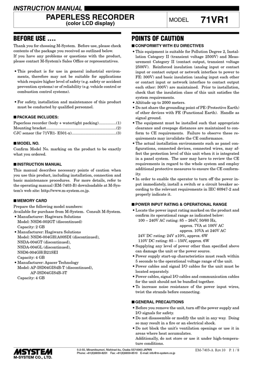
M-system 71VR1 User manual

M-system

M-system 71VR1 User manual

M-system 47LM User manual

M-system

M-system 47LM User manual

M-system KSE-x1 User manual

M-system

M-system KSE-x1 User manual

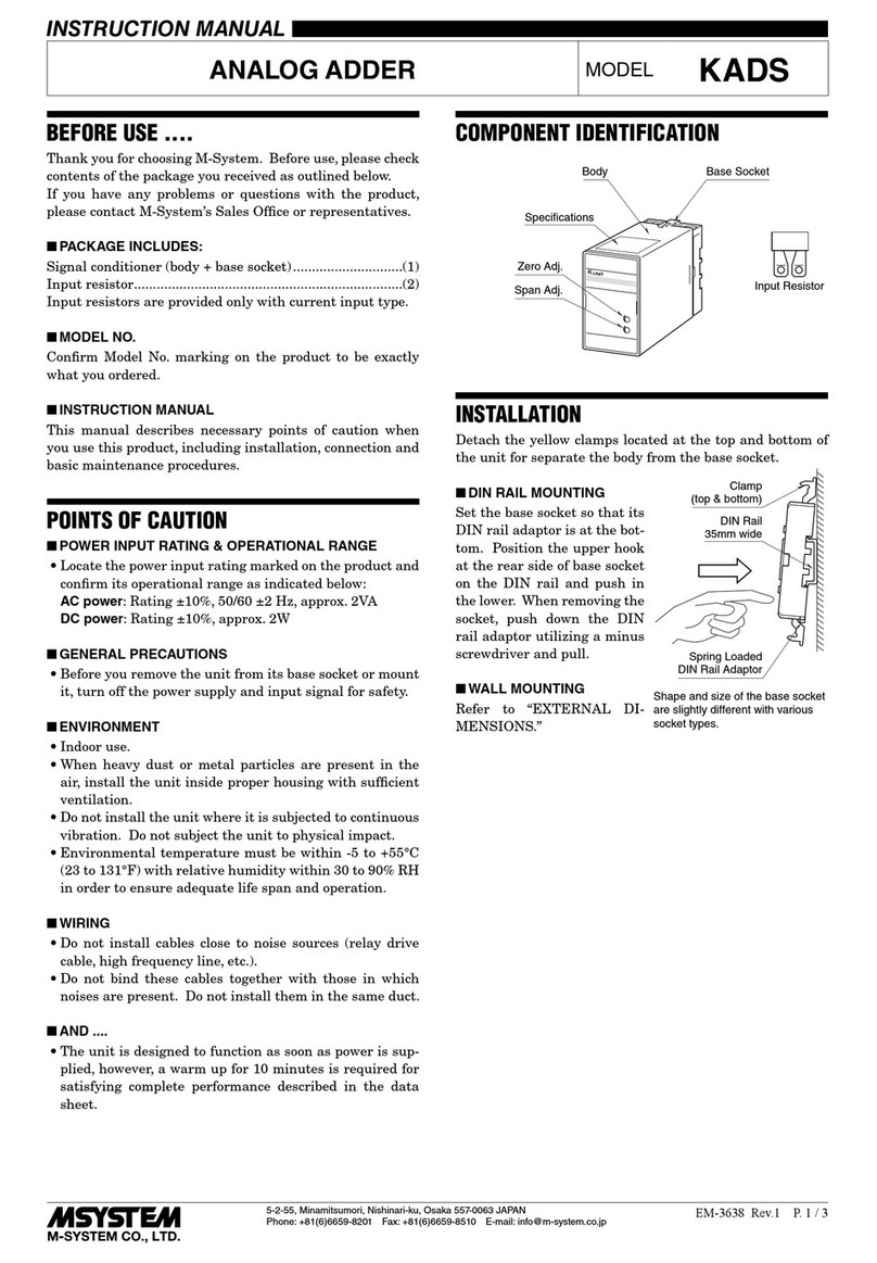
M-system KADS User manual

M-system

M-system KADS User manual

M-system 47LV User manual

M-system

M-system 47LV User manual

M-system 47 Series User manual

M-system

M-system 47 Series User manual

M-system 48NV User manual

M-system

M-system 48NV User manual

M-system 47LR User manual

M-system

M-system 47LR User manual

M-system 47D Series User manual

M-system

M-system 47D Series User manual

M-system R9WTU-ED User manual

M-system

M-system R9WTU-ED User manual

M-system 47DT User manual

M-system

M-system 47DT User manual

M-system 47 Series User manual

M-system

M-system 47 Series User manual

M-system MXAB User manual

M-system

M-system MXAB User manual

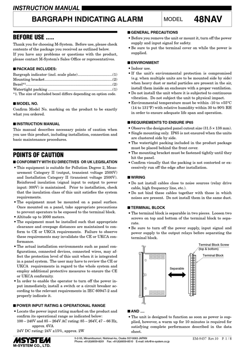
M-system 48NAV User manual

M-system

M-system 48NAV User manual

Popular Measuring Instrument manuals by other brands

Geokon GK-405 quick start guide

Geokon

Geokon GK-405 quick start guide

ATIM Cloud Wireless TH-I user guide

ATIM

ATIM Cloud Wireless TH-I user guide

Trico DR-7 user manual

Trico

Trico DR-7 user manual

ionSign Neutron12-3G quick guide

ionSign

ionSign Neutron12-3G quick guide

Hach BODTrak II user manual

Hach

Hach BODTrak II user manual

Lutron Electronics AM-4220 Operation manual

Lutron Electronics

Lutron Electronics AM-4220 Operation manual

VOLTCRAFT DO-100 operating instructions

VOLTCRAFT

VOLTCRAFT DO-100 operating instructions

Univex FA73 Operator's manual

Univex

Univex FA73 Operator's manual

Technifor TD412 OPERATING AND MAINTENANCE MANUAL INTEGRATION

Technifor

Technifor TD412 OPERATING AND MAINTENANCE MANUAL INTEGRATION

Kentucky MMP instruction manual

Kentucky

Kentucky MMP instruction manual

Amprobe MAN15 user manual

Amprobe

Amprobe MAN15 user manual

Bushnell PRIME 1500 owner's guide

Bushnell

Bushnell PRIME 1500 owner's guide

Ecolab Lubo-DryExx Operating	 instruction

Ecolab

Ecolab Lubo-DryExx Operating instruction

Astrol Electronic BAT-FLEX manual

Astrol Electronic

Astrol Electronic BAT-FLEX manual

teko ASTRA-863 user guide

teko

teko ASTRA-863 user guide

UNAOHM EP2500 manual

UNAOHM

UNAOHM EP2500 manual

CohuHD Costar 3212-2000 quick start guide

CohuHD Costar

CohuHD Costar 3212-2000 quick start guide

Bosch GCL 25 Professional Original instructions

Bosch

Bosch GCL 25 Professional Original instructions

manuals.online logo
manuals.online logoBrands
  • About & Mission
  • Contact us
  • Privacy Policy
  • Terms and Conditions

Copyright 2025 Manuals.Online. All Rights Reserved.