manuals.online logo
Brands
  1. Home
  2. •
  3. Brands
  4. •
  5. M-system
  6. •
  7. Surge Protector
  8. •
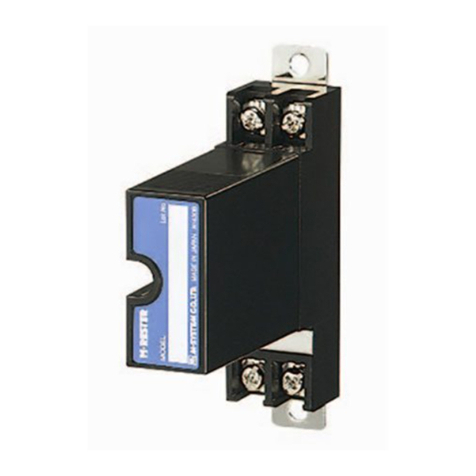
  9. M-system MMAJ User manual

M-system MMAJ User manual

5-2-55, Minamitsumori, Nishinari-ku, Osaka 557-0063 JAPAN
Phone: +81(6)6659-8201 Fax: +81(6)6659-8510 E-mail: info@m-system.co.jp
EM-8155 Rev.2 P. 1 / 4
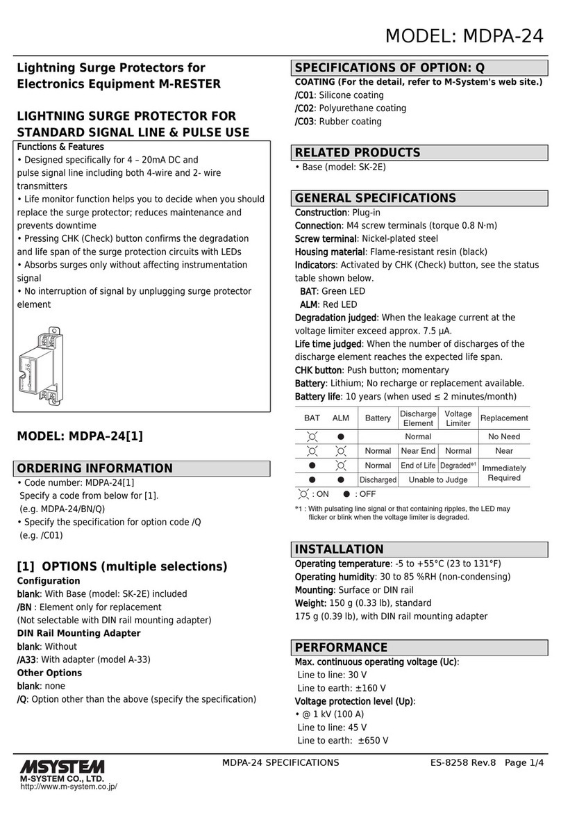
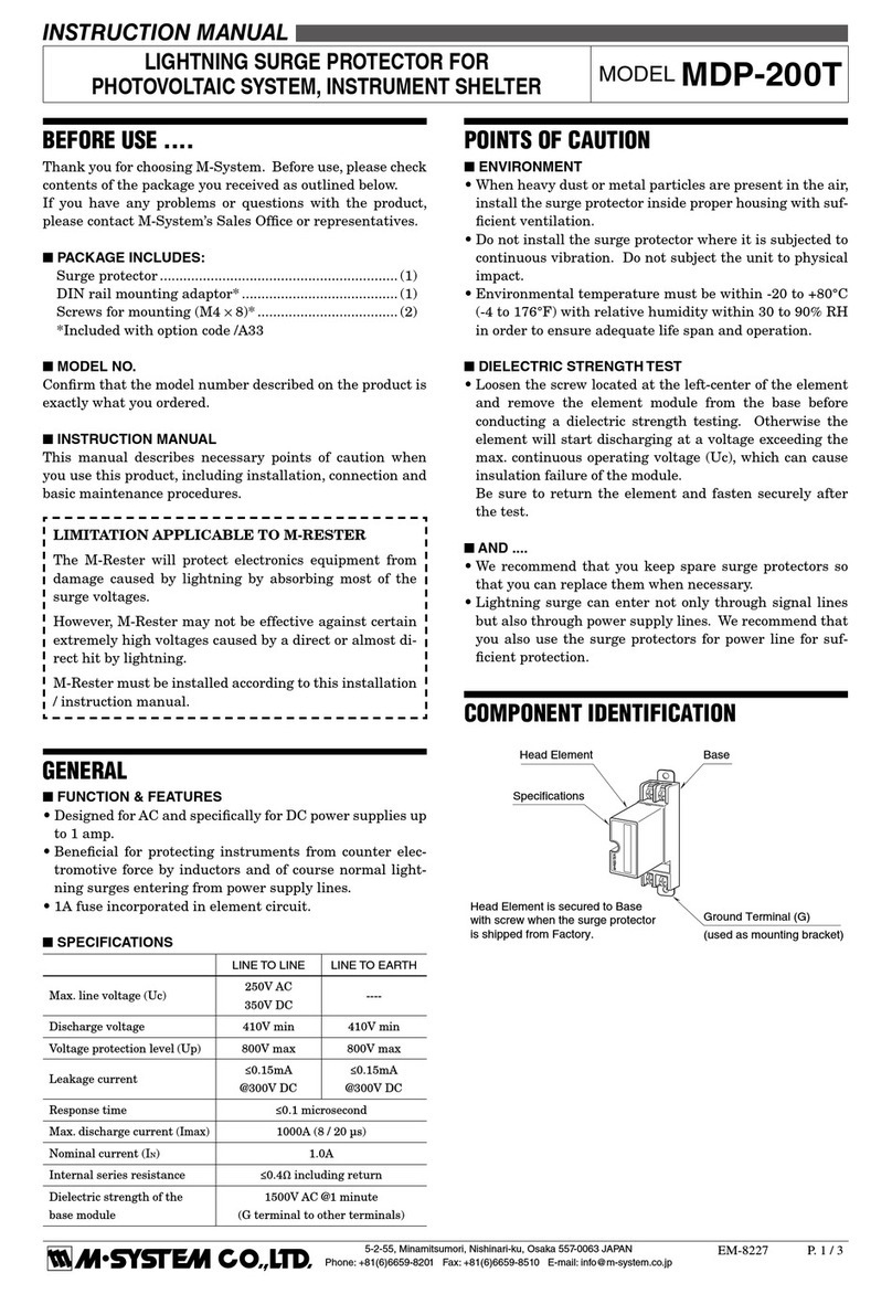
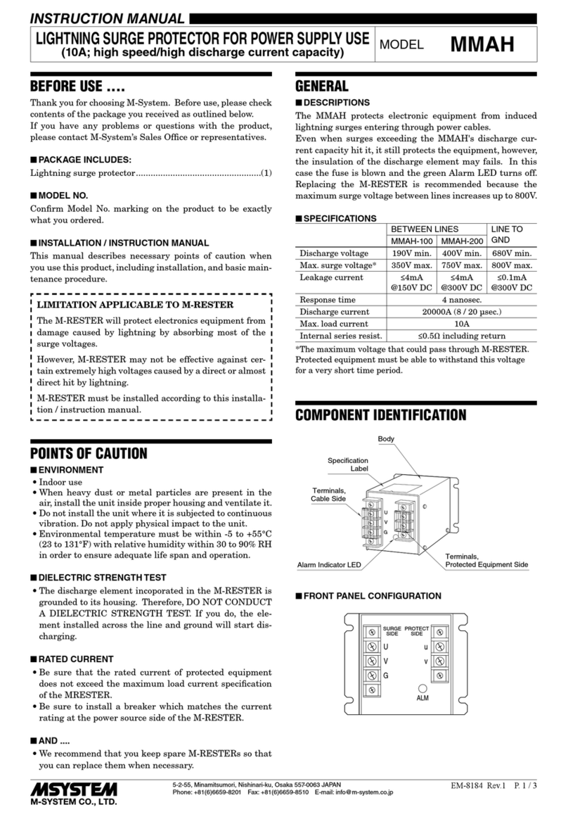
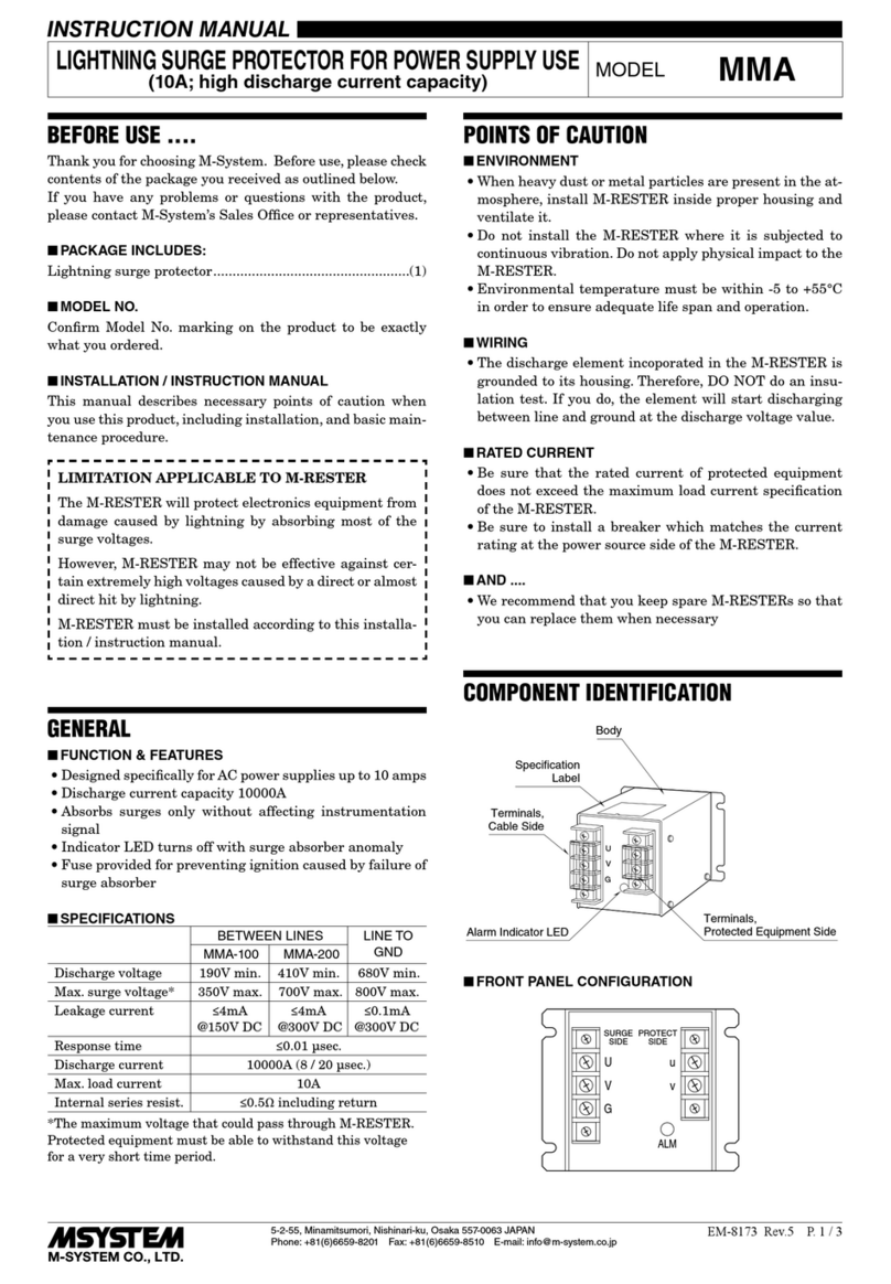
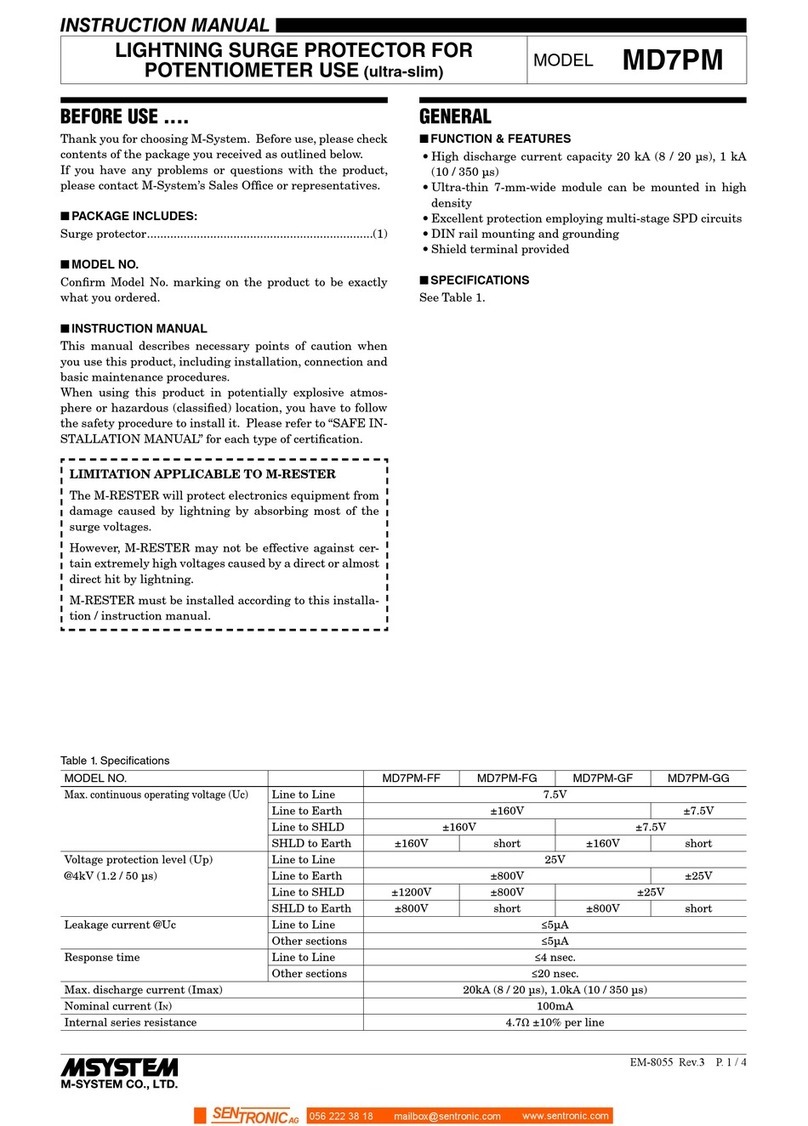
INSTRUCTION MANUAL
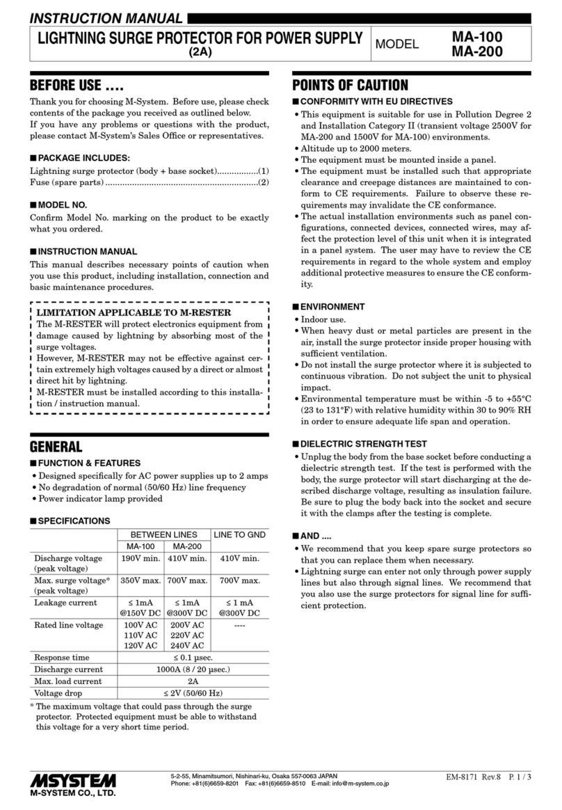
LIGHTNING SURGE PROTECTOR FOR
POWER SUPPLY USE (fast response: 3 nsec.) MODEL MMAJ
BEFORE USE ....
Thank you for choosing M-System. Before use, please check
contents of the package you received as outlined below.
If you have any problems or questions with the product,
please contact M-System’s Sales Office or representatives.
■PACKAGE INCLUDES:
Lightning surge protector...................................................(1)
■MODEL NO.
Confirm Model No. marking on the product to be exactly
what you ordered.
■INSTALLATION / INSTRUCTION MANUAL
This manual describes necessary points of caution when
you use this product, including installation, connection and
basic maintenance procedures.
LIMITATION APPLICABLE TO M-RESTER
The M-RESTER will protect electronics equipment from
damage caused by lightning by absorbing most of the
surge voltages.
However, M-RESTER may not be effective against cer-
tain extremely high voltages caused by a direct or almost
direct hit by lightning.
M-RESTER must be installed according to this installa-
tion / instruction manual.
POINTS OF CAUTION
■ENVIRONMENT
• Indoor use. Install the surge protector on a place where
the monitor LED can be easily visible.
• It is possible to be hit by a certain strong lightning ex-
ceeding the capacity of this unit. The surge protector may
will be destroyed by such high lightning energy. Be sure
to install the surge protector inside a metal enclosure for
safety.
• Do not install the surge protector where it is subjected to
continuous vibration. Do not subject the unit to physical
impact.
• Environmental temperature must be within -5 to +55°C
(23 to 131°F) and with relative humidity within 30 to 90%
RH in order to ensure adequate life span and operation.
• Do not perform the installation, wiring or checking the
M-RESTER during thunder storms.
■DIELECTRIC STRENGTH TEST
• Disconnect the earth conductor before conducting a di-
electric strength test. If the test is performed, connecting
to the earth, the surge protector will start discharging at
the described discharge voltage, resulting as insulation
failure. Be sure to connect the earth conductor after the
testing is complete.
■RATED CURRENT
• Be sure that the rated current of protected device does
not exceed the maximum load current specification of the
M-RESTER.
• Be sure to install a breaker which matches the current
rating at the power source side of the M-RESTER.
■AND....
• We recommend that you keep spare surge protectors so
that you can replace them when necessary.
• Lightning surge can enter not only through signal lines
but also through power supply lines. We recommend that
you also use the surge protectors for power line for suf-
ficient protection.
COMPONENT IDENTIFICATION
U
V
u
v
PE
Monitor
ALM
A2
A1
C
Surge
Side
Protect
Side
Body
Specifications
Monitor LED
Surge Side
Terminals
Earth Terminals
Protect Side
Terminals
Alarm Terminals
*1. Only for “alarm output” option
*1
■FRONT VIEW
U
V
u
v
PE
Monitor
ALM
A2
A1
C
Surge
Side
Protect
Side
MMAJ
5-2-55, Minamitsumori, Nishinari-ku, Osaka 557-0063 JAPAN
Phone: +81(6)6659-8201 Fax: +81(6)6659-8510 E-mail: info@m-system.co.jp
EM-8155 Rev.2 P. 2 / 4
PERFORMANCE
MMAJ-100xxx MMAJ-200xxx
Max. Continuous Operating Voltage (Uc) 132V AC 264V AC
Operational Voltage Range *185 – 132V AC 170 – 264V AC
Discharge Voltage (Vmin) Line to line: 190V
Line to earth: 300V
Line to line: 380V
Line to earth: 450V
Voltage Protection Level (Up) 900V 1500V
Leakage Current @ Uc Line to line: Without Alarm 6mA, With Alarm 20mA
Line to earth: 10μA
Nominal Discharge Current (In) MMAJ-xxL: 5kA
MMAJ-xxM: 10kA
Max. Load Current *2
MMAJ-x10: 10A
MMAJ-x20: 20A
MMAJ-x30: 30A
Voltage Drop ≤ 1V
Surge Energy Attenuation Ratio @8/20 µs
(Line to earth)
MMAJ-10010: -56 dB
MMAJ-10020: -56 dB
MMAJ-10030: -40 dB
MMAJ-20010: -53 dB
MMAJ-20020: -53 dB
MMAJ-20030: -40 dB
Response Time (Line to line) 3 nsec.
Insulation Resistance ≥ 100 MΩ with 500V DC (line to alarm output to housing)
Dielectric Strength 2000V AC @1 minute (line to alarm output to housing)
*1. MMAJ is operational as an SPD despite the voltage less than the minimum. However, the functions of the monitor LED and the
alarm output are not guaranteed.
*2. Refer to Derating Curve
INSTALLATION
Refer to the drawings below. The unit weighs heavily. Mount it on a rigid wall.
■EXTERNAL DIMENSIONS unit: mm (inch)
50 (1.97)
117 (4.61)22
(0.87)
80 (3.15)
88 (3.46)
77 (3.03)
75 (2.95)
11 (0.43)
66 (2.60)
U
V
u
v
PE
Monitor
ALM
A2
A1
C
Surge
Side
Protect
Side
4 – M4 SLOT
■MOUNTING REQUIREMENTS unit: mm (inch)
75 (2.95)
77 (3.03)
50 (1.97)
75 (2.95)
77 (3.03)
4 – M4 SLOT
90 (3.54) min.
MMAJ
5-2-55, Minamitsumori, Nishinari-ku, Osaka 557-0063 JAPAN
Phone: +81(6)6659-8201 Fax: +81(6)6659-8510 E-mail: info@m-system.co.jp
EM-8155 Rev.2 P. 3 / 4
TERMINAL CONNECTIONS
Connect the unit as in the diagram below.
■CONNECTION DIAGRAM
MDJST
6
5
4
3
–
+
4 – 20mA DC
MMAJ-100
V
U
v
u
100V AC
V
U
G
G
PE
A2
A1
*1. Sections enclosed with broken line are applicable for “alarm
output” option.
The schematic shows the relay contact status of a thermal trip
or power off.
*2. Be sure to make a cross-wire. If the protected device has no
earth terminal, earth only the MMAJ.
*2
Protected Device
A MCCB
must be installed.
MCCB
*1
C
■EARTHING
M-RESTER PROTECTED
DEVICE
G
PE (G)
CROSSOVER WIRE
EARTHING
(100 ohms or less)
A crossover wire between M-RESTER and earth or the
metallic housing of device is required for protection.
DERATING CURVE
100
50
0
-5 0204
06
055
20A
30A
10A
Ambient Air Temperature (°C)
Load Rate (%)
WIRING
■LEADWIRES
Conductor cross-section area: 5.5 mm2minimum for U, V
and PE lines. However, a local industrial standard require-
ment for wiring should take precedence.
The wire length should ideally be less than 0.5 meters. Ex-
tra long wires should not be bundled in coils, but be cut to
the minimum required length.
■SOLDERLESS TERMINAL
Applicable ring tongue terminal without insulation sleeve
is as indicated below. Spade tongue terminal must conform
with the ring type size.
In order to ensure IP20 protection (IEC 60529) with a sol-
derless terminal, cover the terminal with a insulation cap
to prevent direct touching by a hand.
F
d: M4 use
B≤11.0 mm
F≥ 5.5 mm
(F≥ 7 mm
for sharing terminals)
T≤ 1.5 mm
• Applicable Solderless Terminal Size
diameter d
BT
■TORQUE
Tighten the screw terminals securely. Maximum allowable
torque is of 1.2 N·m.
ALARM OUTPUT
The power supply voltage is continuously applied to the in-
corporated discharge element (zinc oxide element). Degrad-
ed element is automatically separated from the power lines
for safety to prevent overheating caused by leakage current.
Optional SPDT relay output is available to alert when the
thermal breaker has separated the discharge element from
the power supply circuit.
If the alarm output should be transmitted remotely via
outdoor cables, a surge protector for signal line is required.
Choose a circuit breaker with an alarm output. Configure a
logical addition sequence so that the alarm trips when both
or either of the M-RESTETR or the breaker alarm trips.
■RELAY SPECIFICATIONS
Alarm output: The SPDT relay trips when the thermal
breaker operates and/or power source shutdown.
Rated load: 250V AC @1A (resistive load)
24V DC @1A (resistive load)
OUTPUT
TERMINAL NORMAL THERMAL BREAKER OPERATING OR
POWER OFF
A1 – C Open Close
A2 – C Close Open
■CONNECTION
Terminal: Tension clamp
Applicable wire size: 0.33 to 1.5 mm2( 6 – 7 mm exposed)
MMAJ
5-2-55, Minamitsumori, Nishinari-ku, Osaka 557-0063 JAPAN
Phone: +81(6)6659-8201 Fax: +81(6)6659-8510 E-mail: info@m-system.co.jp
EM-8155 Rev.2 P. 4 / 4
CHECKING
■WIRING
• Make sure that wiring is done as instructed in the con-
nection diagram.
• Make sure that the Earth terminal is connected to the
metallic housing of protected device.
• Make sure that the Earth terminal is connected to earth.
MAINTENANCE
Even lightning in remote locations could induce surges
without our knowledge. Regular checking of the surge pro-
tector is important to find degradations in early stage, be-
fore and after the storm seasons, and whenever you experi-
ence a strong lightning storm.
DO NOT attempt checking or replacing the surge protector
during a thunderstorm for safety.
Checking procedure is as explained below.
■MONITOR LED & ALARM
Configure the state of the monitor LED and the alarm out-
put with the power voltage supplied. Replace in case of fail-
ure/breakdown.
MONITOR
LED
ALARM OUTPUT
A1 – C A2– C
Normal ON Open Close
Failure/ Power OFF OFF Close Open
■SIMPLE CHECK
The alarm output or the monitor LED could be broken even
with no indication. The steps below explain a simple proce-
dure to check it.
1. Remove all wiring connected to the M-RESTER.
2. Confirm there is no conduction across the terminals indi-
cated below, with a 100/125 V DC insulation tester.
TERMINALS DUE RESULT
U – PE ≥ 10MΩ
V – PE
3. Check with a 1000 V DC insulation tester across the ter-
minals indicated below and confirm it discharges.
TERMINALS DUE RESULT
U – PE ≤ 2MΩ
V – PE
4. Turn on the power supply with no load and measure the
current flowing into the M-RESTER.
MODEL DUE RESULT
MMAJ-100xxY ≤ 6mA
MMAJ-200xxY
MMAJ-100xxA ≤ 20mA
MMAJ-200xxA
If any of the above tests shows negative, replace the M-
RESTER.

Other M-system Surge Protector manuals

M-system MDP-65T User manual

M-system

M-system MDP-65T User manual

M-system MDP-LWA User manual

M-system

M-system MDP-LWA User manual

M-system MDP-DM3 User manual

M-system

M-system MDP-DM3 User manual

M-system MGD-24 User manual

M-system

M-system MGD-24 User manual

M-system MDPA-24 User manual

M-system

M-system MDPA-24 User manual

M-system MGA-100 User manual

M-system

M-system MGA-100 User manual

M-system MDP-RB User manual

M-system

M-system MDP-RB User manual

M-system MDP-PM User manual

M-system

M-system MDP-PM User manual

M-system MDCAT-SPE User manual

M-system

M-system MDCAT-SPE User manual

M-system MD7LWA User manual

M-system

M-system MD7LWA User manual

M-system MD7PL User manual

M-system

M-system MD7PL User manual

M-system MMH-1 User manual

M-system

M-system MMH-1 User manual

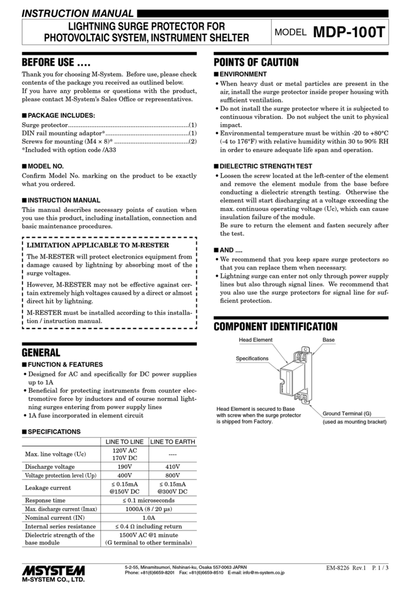
M-system MDP-100T User manual

M-system

M-system MDP-100T User manual

M-system MDP-SP User manual

M-system

M-system MDP-SP User manual

M-system MD-LC2 Service manual

M-system

M-system MD-LC2 Service manual

M-system MDP-JS User manual

M-system

M-system MDP-JS User manual

M-system MDP-200T User manual

M-system

M-system MDP-200T User manual

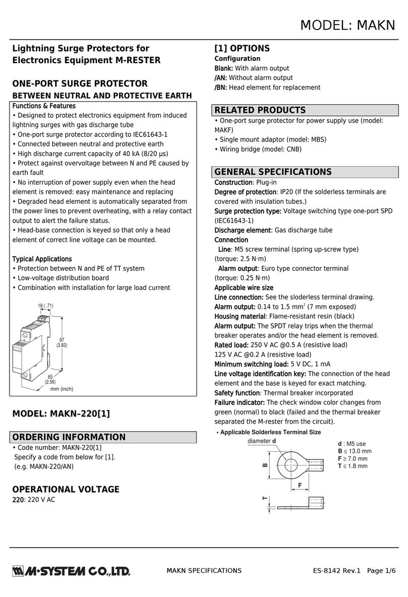
M-system MAKN User manual

M-system

M-system MAKN User manual

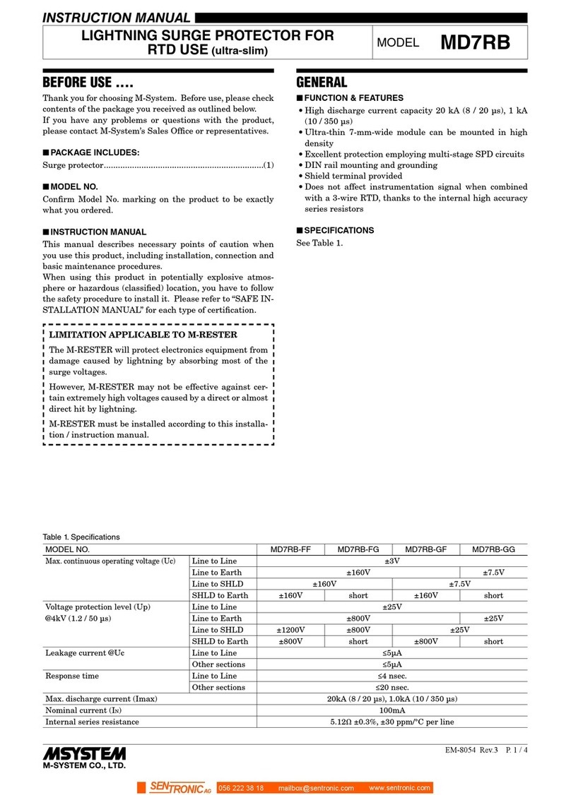
M-system MD7RB-FF User manual

M-system

M-system MD7RB-FF User manual

M-system MDP-D Series User manual

M-system

M-system MDP-D Series User manual

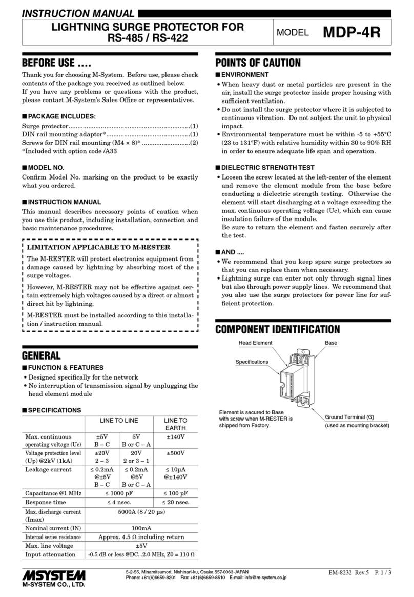
M-system MDP-4R User manual

M-system

M-system MDP-4R User manual

M-system MD7TC User manual

M-system

M-system MD7TC User manual

M-system MDPA-24 User manual

M-system

M-system MDPA-24 User manual

M-system MA-100 User manual

M-system

M-system MA-100 User manual

Popular Surge Protector manuals by other brands

Superior Electric STABILINE DIN3-165 Series owner's manual

Superior Electric

Superior Electric STABILINE DIN3-165 Series owner's manual

SC&T SP008 user manual

SC&T

SC&T SP008 user manual

LEGRAND Wiremold Perma Power M6BZ-15 installation instructions

LEGRAND

LEGRAND Wiremold Perma Power M6BZ-15 installation instructions

Patton electronics 536S user manual

Patton electronics

Patton electronics 536S user manual

Siemens 5SD7 502-0KB operating instructions

Siemens

Siemens 5SD7 502-0KB operating instructions

Intermatic IG2200 installation instructions

Intermatic

Intermatic IG2200 installation instructions

CyberPower CSB600WS user manual

CyberPower

CyberPower CSB600WS user manual

Transtector CPX Series installation instructions

Transtector

Transtector CPX Series installation instructions

Nivus EnerPro220Tr/20kA operating instructions

Nivus

Nivus EnerPro220Tr/20kA operating instructions

Ditek D200-347/6003Y Install instructions

Ditek

Ditek D200-347/6003Y Install instructions

Supra MD08EU/SP quick start guide

Supra

Supra MD08EU/SP quick start guide

Outback Power Systems FLEXWARE FW-SP-250 user guide

Outback Power Systems

Outback Power Systems FLEXWARE FW-SP-250 user guide

ABB REU615 manual

ABB

ABB REU615 manual

ATOMI AT1628 user manual

ATOMI

ATOMI AT1628 user manual

Clamper Solar SB 1040V 16A 4E/2S P18 installation guide

Clamper

Clamper Solar SB 1040V 16A 4E/2S P18 installation guide

Energenie SPF5-C-5 user manual

Energenie

Energenie SPF5-C-5 user manual

Leviton 3812 installation instructions

Leviton

Leviton 3812 installation instructions

Ditek DTK-TSS5 user guide

Ditek

Ditek DTK-TSS5 user guide

manuals.online logo
manuals.online logoBrands
  • About & Mission
  • Contact us
  • Privacy Policy
  • Terms and Conditions

Copyright 2025 Manuals.Online. All Rights Reserved.