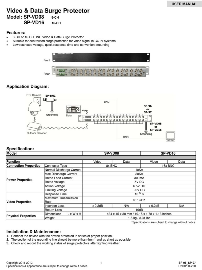
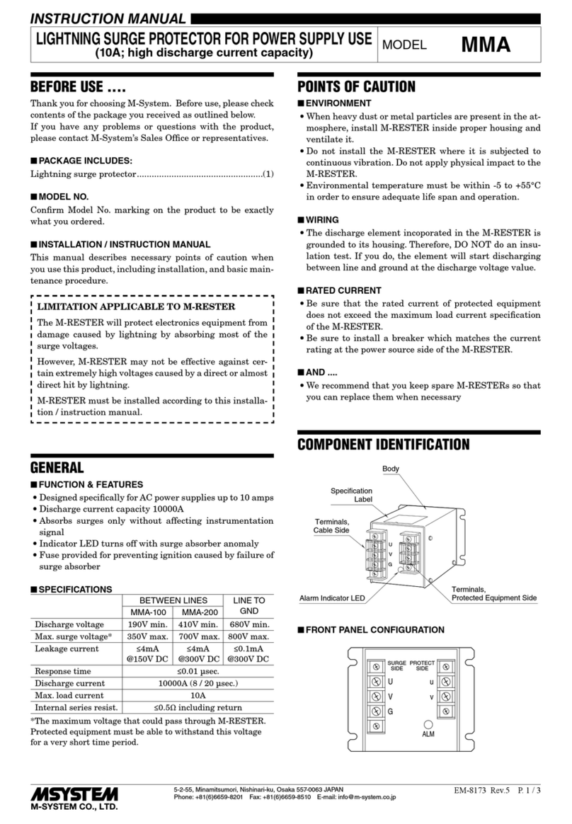
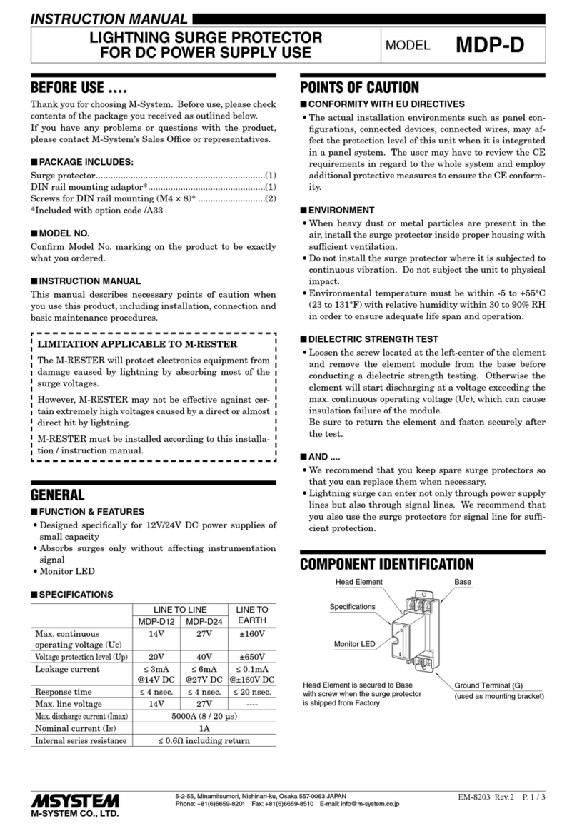
manuals.online logo
Brands
  1. Home
  2. •
  3. Brands
  4. •
  5. M-system
  6. •
  7. Surge Protector
  8. •
  9. M-system MDCAT-SPE User manual

M-system MDCAT-SPE User manual

5-2-55, Minamitsumori, Nishinari-ku, Osaka 557-0063 JAPAN
Phone: +81(6)6659-8201 Fax: +81(6)6659-8510 E-mail: info@m-system.co.jp
EM-8196 P. 1 / 3
INSTRUCTION MANUAL
BEFORE USE ....
Thank you for choosing M-System. Before use, please check
contents of the package you received as outlined below.
If you have any problems or questions with the product,
please contact M-System’s Sales Office or representatives.
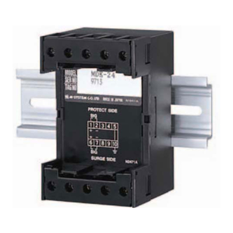
■PACKAGE INCLUDES:
Surge protector....................................................................(1)
Single mount DIN rail ........................................................(1)
(Only for option code ‘/DR’ selected)
■MODEL NO.
Confirm Model No. marking on the product to be exactly
what you ordered.
■INSTRUCTION MANUAL
This manual describes necessary points of caution when
you use this product, including installation, connection and
basic maintenance procedures.
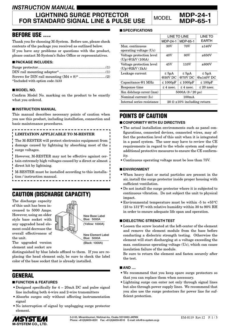
LIMITATION APPLICABLE TO M-RESTER
The M-RESTER will protect electronics equipment from
damage caused by lightning by absorbing most of the
surge voltages.
However, M-RESTER may not be effective against cer-
tain extremely high voltages caused by a direct or almost
direct hit by lightning.
M-RESTER must be installed according to this installa-
tion / instruction manual.
POINTS OF CAUTION
■ENVIRONMENT
• Indoor use.
• When heavy dust or metal particles are present in the
air, install the surge protector inside proper housing with
sufficient ventilation.
• Do not install the surge protector where it is subjected to
continuous vibration. Do not subject the unit to physical
impact.
• Environmental temperature must be within -25 to +85°C
(-13 to +185°F) with relative humidity within 10 to 90%
RH in order to ensure adequate life span and operation.
• This unit can be earthed via a DIN rail. Oxide film on the
surface of an aluminum rail may lower the electric con-
ductivity between this module and the ground. When this
unit is earthed via a DIN rail, use a steel or copper rail.
• Steel rails may be coated with thin oxide film. Discharg-
ing surge current may produce sparks with the film.
However, this does not affect the surge protection. If you
need to avoid sparks, prior to mounting on the DIN rail,
remove the film by a wire brush.
• Single mount DIN rail for option code ‘/DR’ is made of alu-
minum. Connect to ground with ground terminal when
this DIN rail is used.
■AND ....
• We recommend that you keep spare surge protectors so
that you can replace them when necessary.
• Lightning surge can enter not only through signal lines
but also through power supply lines. We recommend that
you also use the surge protectors for power line for suf-
ficient protection.
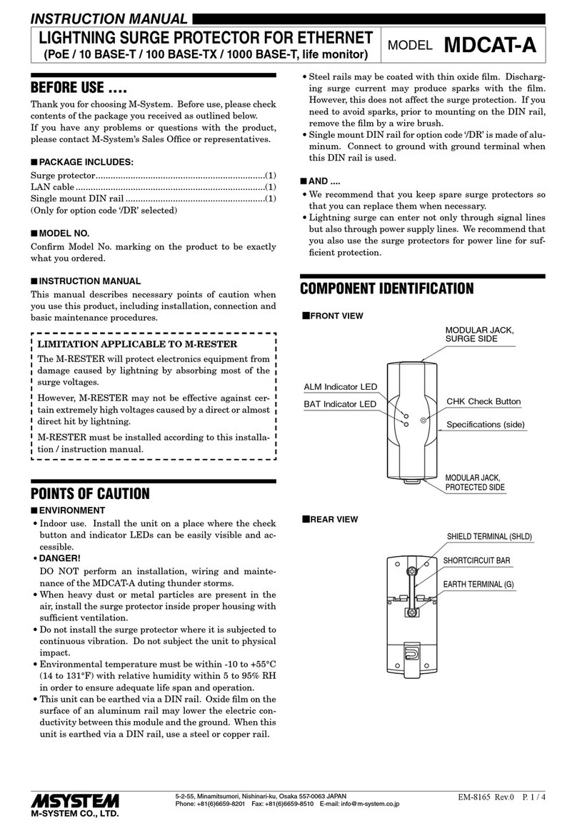
COMPONENT IDENTIFICATION
SURGE SIDE
CONNECTOR
Body
Specifications
SHORTCIRCUIT BAR PROTECTED SIDE
CONNECTOR
DIN rail adaptor
SHIELD TERMINAL
EARTH TERMINAL
Side (hidden)
INSTALLATION
Mount the unit on a DIN rail. Once installed, do not move
it to another DIN rail.
■MOUNTING THE UNIT ON A DIN RAIL
A)Hang the upper hook of the DIN rail mounting adaptor at
the rear side of unit, on the DIN rail.
B)Push in the lower in keeping pressing the unit to the DIN
rail.
ADIN rail
B
■REMOVING THE UNIT
A)Pull down the DIN rail adaptor utilizing a minus screw-
driver.
B)Pull out the lower part of the unit.
C)Detach the upper part from the DIN rail.
CB
A
Slider
LIGHTNING SURGE PROTECTOR FOR SINGLE PAIR ETHERNET
(PoDL) MODEL
MDCAT-SPE
MDCAT-SPE
5-2-55, Minamitsumori, Nishinari-ku, Osaka 557-0063 JAPAN
Phone: +81(6)6659-8201 Fax: +81(6)6659-8510 E-mail: info@m-system.co.jp
EM-8196 P. 2 / 3
TERMINAL CONNECTIONS
Connect the unit as in the diagram below.
■EXTERNAL DIMENSIONS unit: mm [inch]
• When mounting, no extra space is needed between units.
38 [1.50]
90 [3.54]10 [.39] 10 [.39]
DIN RAIL
(35mm wide)
(3 [.12])
40 [1.57]
SURGE SIDE
CONNECTOR
PROTECTED SIDE
CONNECTOR
SHIELD TERMINAL (SHLD)
EARTH TERMINAL (G)
35 [1.38]
6 [.24] (4.5 [.18] deep)
321
CBA
SHORTCIRCUIT BAR
11
[.43]
50 [1.97]
4.2 [.17]
35 [1.38]
7.3 [.29]
■DIN RAIL
■UNIT
■CONNECTION DIAGRAM
1
2
3
A
B
C
G
SHLD
+
–
SHLD
FG
Protected sideSurge Side
MDCAT-SPE
*1*2
*3, *4
*1. Use shortcircuit bar to ground the shield.
*2. If the protected device has an FG terminal, connect to the G terminal of the MDCAT-SPE.
*3. Use a DIN rail made of steel or copper when connecting to ground via the DIN rail.
*4. Single mount DIN rail for option code ‘/DR’ is made of aluminum.
Connect to ground with ground terminal when this DIN rail is used.
Shielded Cable
Protected Device
MDCAT-SPE
5-2-55, Minamitsumori, Nishinari-ku, Osaka 557-0063 JAPAN
Phone: +81(6)6659-8201 Fax: +81(6)6659-8510 E-mail: info@m-system.co.jp
EM-8196 P. 3 / 3
■WIRING INSTRUCTIONS
Applicable wire size range for euro type connector terminal
of communication is as shown below.
• Applicable wire size
Solid: 0.2 to 2.5 mm2(0.55 to 1.75 dia.)
Stranded: 0.2 to 2.5 mm2
Tinning wire ends may cause contact failure
and therefore is not recommended.
Ferruled: 0.2 to 1.5 mm2(0.55 to 1.35 dia.)
The following Phoenix Contact terminals are recommended:
AI 0.25-8YE 0.2 to 0.25 mm2
AI 0.34-8TQ 0.25 to 0.34 mm2
AI 0.5-8WH 0.34 to 0.5 mm2
AI 0.75-8GY 0.5 to 0.75 mm2
AI 1.0-8RD 0.75 to 1.0 mm2
AI 1.5-8BK 1.0 to 1.5 mm2
• Expose wire conductors by 8 mm (0.31”).
8 mm 8 mm
4 mm dia.
max.
4 mm dia.
max.
Wire exposure Recommended
ferruled wire
MAINTENANCE
Check surge protectors periodically. Many cases of light-
ning are ignored, and even lightning at a far distance often
causes inductive surges.
We recommend that you check your surge protector about
twice a year, before and after the rainy season. Check
whenever you experience a strong lightning occurrence.
Checking procedure is explained in the following:
■CHECKING
1. WIRING
• Make sure that wiring is done as instructed in the con-
nection diagram.
2. DISCHARGE ELEMENT
Approximate checking can be conducted as following.
• Shortcircuit test
1) Remove all cables connected to the MDCAT-SPE.
2) Remove also the shortcircuit bar.
3) Check resistance across the following terminals on the
high resistance range of multimeter and confirm no con-
duction. (The meter will indicate the same value as it
will show when these terminals are open.)
(1)-G, (2)-G, (3)-G
4) Then, apply ±60V DC across the following terminals and
measure leakage current to show ≤ 5µA. If a voltage gen-
erator is not available, check resistance with a multim-
eter and confirm no conduction. (Use of a voltage genera-
tor is strongly recommended.)
• Discharging test
1) Check that discharging occurs across the following termi-
nals with a ±500V DC 1000 MΩ insulation tester.
(The tester shows ≤ 20MΩ.)
(1)-G, (2)-G, (3)-G

Other M-system Surge Protector manuals

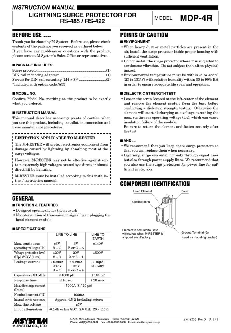
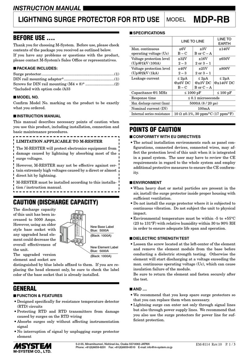
M-system MDP-RB User manual

M-system

M-system MDP-RB User manual

M-system MDP-100 User manual

M-system

M-system MDP-100 User manual

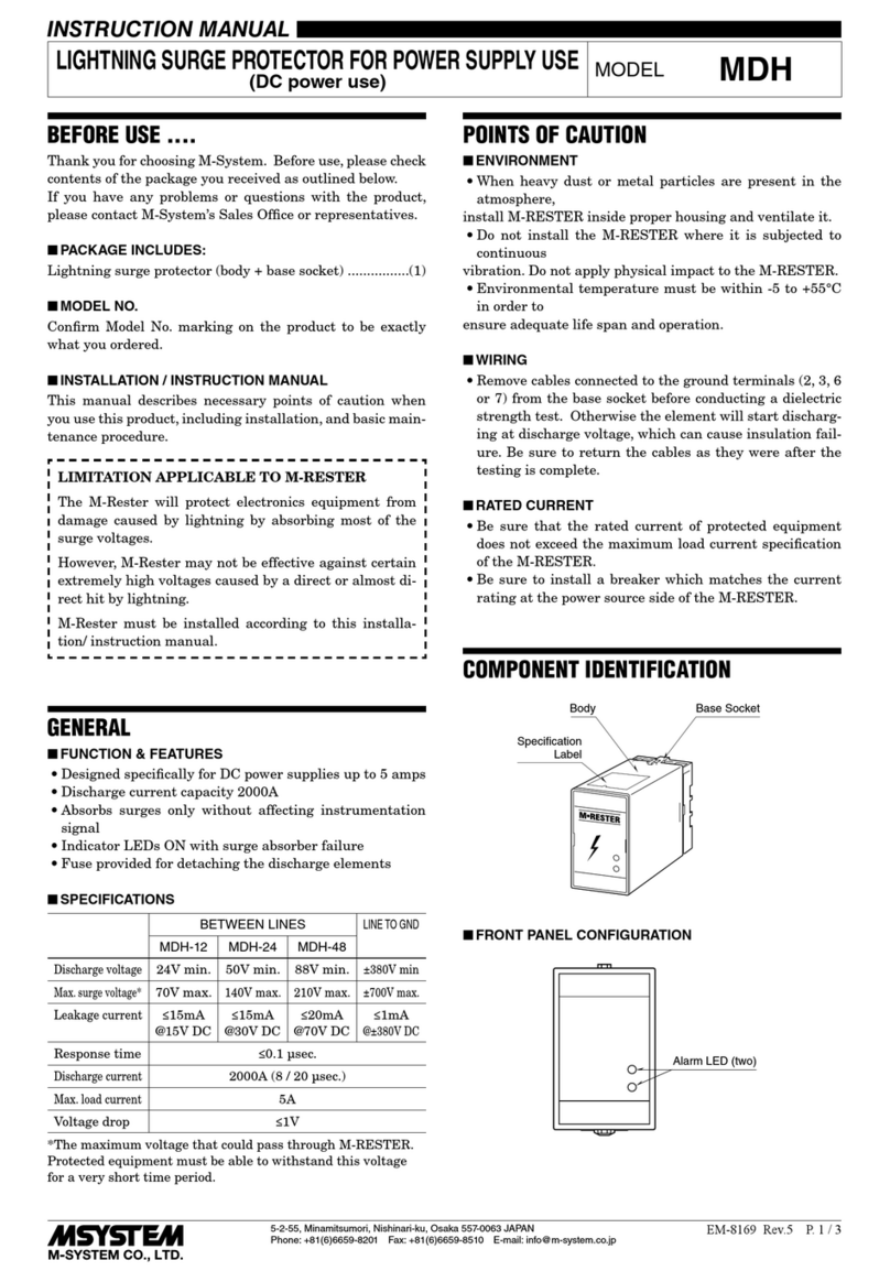
M-system MDH User manual

M-system

M-system MDH User manual

M-system MMAJ User manual

M-system

M-system MMAJ User manual

M-system MDP-JS User manual

M-system

M-system MDP-JS User manual

M-system 6SN User manual

M-system

M-system 6SN User manual

M-system MDPA-24 User manual

M-system

M-system MDPA-24 User manual

M-system MD-LC2 Service manual

M-system

M-system MD-LC2 Service manual

M-system MD7JS User manual

M-system

M-system MD7JS User manual

M-system MD7PL User manual

M-system

M-system MD7PL User manual

M-system MMAH Series User manual

M-system

M-system MMAH Series User manual

M-system MDPA-24 User manual

M-system

M-system MDPA-24 User manual

M-system MD7G User manual

M-system

M-system MD7G User manual

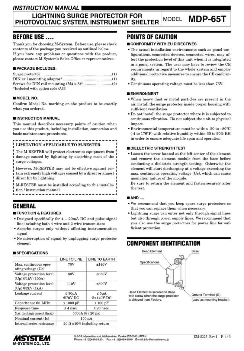
M-system MDP-65T User manual

M-system

M-system MDP-65T User manual

M-system MGD-24 User manual

M-system

M-system MGD-24 User manual

M-system MDA-TL User manual

M-system

M-system MDA-TL User manual

M-system MDP-100T User manual

M-system

M-system MDP-100T User manual

M-system MDR2 User manual

M-system

M-system MDR2 User manual

M-system MDP-4R User manual

M-system

M-system MDP-4R User manual

M-system MDP-SP User manual

M-system

M-system MDP-SP User manual

M-system MD7PM User manual

M-system

M-system MD7PM User manual

M-system MH-1201 User manual

M-system

M-system MH-1201 User manual

M-system MMA User manual

M-system

M-system MMA User manual

M-system MAL-230x User manual

M-system

M-system MAL-230x User manual

Popular Surge Protector manuals by other brands

CyberPower HT1210TC user manual

CyberPower

CyberPower HT1210TC user manual

Vimar 00447.CK.B instruction manual

Vimar

Vimar 00447.CK.B instruction manual

Ditek DTK-DF240S12 user guide

Ditek

Ditek DTK-DF240S12 user guide

Ilsco SSI SpecPRO SRM 26 Series manual

Ilsco

Ilsco SSI SpecPRO SRM 26 Series manual

Ametek Surgex SA-20-AR user manual

Ametek

Ametek Surgex SA-20-AR user manual

Bauhn ASPP8-0723-W user guide

Bauhn

Bauhn ASPP8-0723-W user guide

UTEPO USP201E quick start guide

UTEPO

UTEPO USP201E quick start guide

SC&T SP008 user manual

SC&T

SC&T SP008 user manual

CyberPower CSP606U42A quick guide

CyberPower

CyberPower CSP606U42A quick guide

Mersen Surge-Trap ST-50 Series installation instructions

Mersen

Mersen Surge-Trap ST-50 Series installation instructions

Eufficio Innera Molla installation instructions

Eufficio

Eufficio Innera Molla installation instructions

360 electrical Revolve45 user guide

360 electrical

360 electrical Revolve45 user guide

MTL Surge Technologies TP-P48 installation guide

MTL Surge Technologies

MTL Surge Technologies TP-P48 installation guide

Total Protection Solutions ComTrack TK-CT2-PHONE-RJ Installation, operation and maintenance instructions

Total Protection Solutions

Total Protection Solutions ComTrack TK-CT2-PHONE-RJ Installation, operation and maintenance instructions

Hubbell HBLSDSA36 Installation instruction

Hubbell

Hubbell HBLSDSA36 Installation instruction

Radio Shack 61-2402 owner's manual

Radio Shack

Radio Shack 61-2402 owner's manual

novaris CN-FF-zz-3-E installation instructions

novaris

novaris CN-FF-zz-3-E installation instructions

Intermatic AG3000 Installation instruction

Intermatic

Intermatic AG3000 Installation instruction

manuals.online logo
manuals.online logoBrands
  • About & Mission
  • Contact us
  • Privacy Policy
  • Terms and Conditions

Copyright 2025 Manuals.Online. All Rights Reserved.