M-system M2XRP2 User manual

M2XRP2
P. 1 / 5EM-5059 Rev.5
ENCODER SPEED TRANSMITTER(PC programmable; built-in excitation)MODELM2XRP2INSTRUCTION MANUALBEFORE USE ....
Thank you for choosing M-System. Before use, please check
contents of the package you received as outlined below.
If you have any problems or questions with the product,
please contact M-System’s Sales Office or representatives.
■ PACKAGE INCLUDES:Signal conditioner (body + base socket) ...................... (1)
■ MODEL NO.Confirm Model No. marking on the product to be exactly
what you ordered.
■ INSTRUCTION MANUALThis manual describes necessary points of caution when
you use this product, including installation, connection and
basic maintenance procedures.
To change I/O ranges, the JX Configurator Connection Kit
(model: JXCON) is required. For detailed information, refer
to the data sheet and instruction manual for the JXCON.
POINTS OF CAUTION
■ NONINCENDIVE APPROVAL OPTION• This equipment is suitable for use in Class I, Div. 2, Groups
A, B, C and D or Non-Hazardous Locations only.
• WARNING! Before You Remove the Unit from Its Base
Socket or Mount It, Turn Off the Power Supply and Input
Signal for Safety.
• WARNING! – Explosion Hazard –
Substitution of Components May Impair Suitability for
Class I, Div. 2.
• WARNING! – Explosion Hazard –
Do Not Disconnect Equipment Unless Power Has Been
Switched Off or The Area is Known To Be Non-Hazard-
ous.
• The equipment was evaluated for use in the ambient tem-
perature and relative humidity as mentioned in ‘ENVI-
RONMENT’ section.
• The input and output wiring must be in accordance with
Class I, Div. 2 wiring methods and in accordance with the
authority having jurisdiction for use in these hazardous
locations.
■ CONFORMITY WITH EC DIRECTIVES OR UL• This equipment is suitable for use in a Pollution Degree
2 environment and in Installation Category II, with the
maximum operating voltage of 300V.
Basic insulation is maintained between signal input and
output. The voltage across the input terminals is limited
to 70V or less. Prior to installation, check that the insula-
tion class of this unit satisfies the system requirements.
• Altitude up to 2000 meters
• The equipment must be mounted inside a panel.
• Risk of Electrical Shock: The front cover of the panel is to
be opened only by qualified service personnel.
• The equipment must be installed such that appropriate
clearance and creepage distances are maintained to con-
form to CE/UL requirements. Failure to observe these re-
quirements may invalidate the CE/UL conformance.
■ POWER INPUT RATING & OPERATIONAL RANGE• Locate the power input rating marked on the product and
confirm its operational range as indicated below:
100 – 240V AC rating: 85 – 264V (90 – 264V for UL),
47 – 66 Hz, approx. 4 – 6VA
24V DC rating: 24V ±10%, approx. 3W
110V DC rating: 85 – 150V (110V ±10% for UL), approx. 3W
■ WARNING!• To protect very delicate components contained inside
the unit against damage from static electricity, wear a
grounded wrist strap when handling them. If you do not
have one, touch both of your hands to a safely grounded
object or to a metal object.
• Ensure that the power supply and input signal are
switched off before you plug in or remove the unit.
■ ENVIRONMENT• Indoor use
• When heavy dust or metal particles are present in the air,
install the unit inside proper housing with sufficient ven-
tilation.
• Do not install the unit where it is subjected to continuous
vibration. Do not subject the unit to physical impact.
• Environmental temperature must be within -5 to +55°C
(23 to 131°F) with relative humidity within 30 to 90% RH
in order to ensure adequate life span and operation.
• Be sure that the ventilation slits are not covered with ca-
bles, etc.
■ WIRING• Do not install cables (power supply, input and output)
close to noise sources (relay drive cable, high frequency
line, etc.).
• Do not bind these cables together with those in which
noises are present. Do not install them in the same duct.
■ AND ....• The unit is designed to function as soon as power is sup-
plied, however, a warm up for 20 minutes is required for
satisfying complete performance described in the data
sheet.
M2XRP2
P. 2 / 5EM-5059 Rev.5
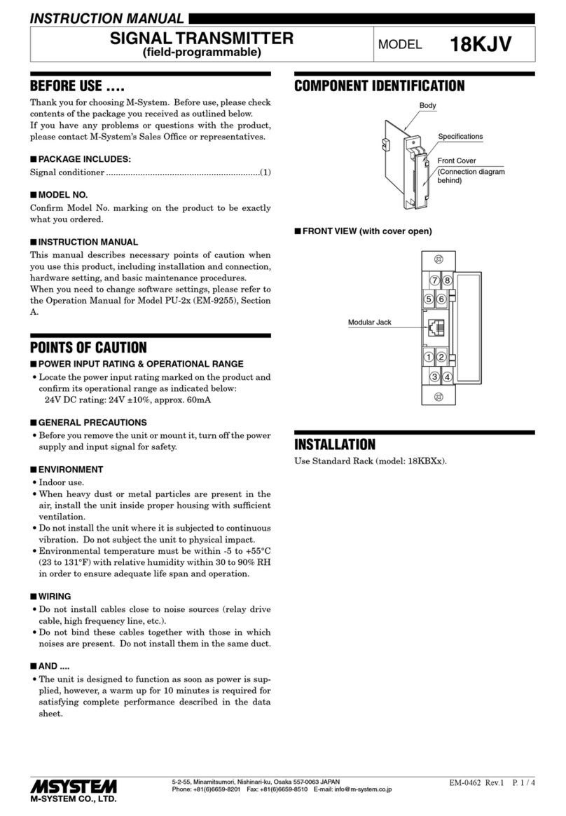
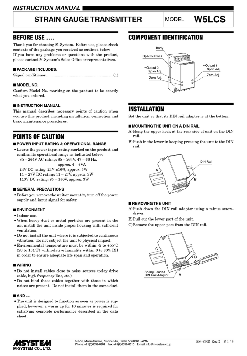
COMPONENT IDENTIFICATION
■ HOW TO OPEN THE LEFT SIDE COVERInsert the tip of a minus driver into the openings indicated
with arrows in the figure, and pull up the cover.
■ HOW TO CLOSE THE LEFT SIDE COVERPlace the side A first and push in the parts B, gently not to
break the enclosure.
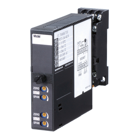
INSTALLATION
Loosen the fixing screw at the front of the unit in order to
separate the body from the base socket.
■ DIN RAIL MOUNTINGSet the base socket so that
its DIN rail adaptor is at
the bottom. Position the
upper hook at the rear side
of base socket on the DIN
rail and push in the lower.
When removing the socket,
push down the DIN rail
adaptor utilizing a minus
screwdriver and pull.
■ WALL MOUNTINGRefer to ‘EXTERNAL DI-
MENSIONS.’
Model
Body Base Socket
Fixing Screw
Connection
Diagram
Specifications
A
B
DIN Rail
35mm wide
Spring Loaded
DIN Rail Adaptor
EXTERNAL DIMENSIONS unit: mm (inch)
4
8 7
1011
56
123
9
21.5 (.85)
70.5 (2.78)
86.7 (3.41)7.3 (.29) 22 (.87)
6 (.23)
59 (2.32)
DIN RAIL
35mm wide
[4 (.16)]
11–M3
SCREW
72 (2.83)4 (.16)
29.5 (1.16)
2–4.2x5
(.17x.20)
MTG HOLE
6 (.24) deep
116.7 (4.59)
• When mounting, no extra space is needed between units.

M2XRP2
P. 3 / 5EM-5059 Rev.5
TERMINAL CONNECTIONS
Connect the unit as in the diagram below or refer to the con-
nection diagram on the side of the unit.
CHECKING
1) Terminal wiring: Check that all cables are correctly con-
nected according to the connection diagram.
2) Check DIP switch setting.
3) Power input voltage: Check voltage across the terminal
10 – 11 with a multimeter.
4) Input: Check that the input voltage is within 0 – 100% of
full-scale.
5) Output: Check that the load resistance meets the de-
scribed specifications.
6) Status indicator LED: Check that it flashes in the nor-
mal patterns.
ZERO/SPAN ADJUSTMENTS
This unit is calibrated at the factory to meet the ordered
specifications, therefore you usually do not need any cali-
bration.
For matching the signal to a receiving instrument or in case
of regular calibration, fine zero and span adjustments can
be done to ±5% by pressing UP/DOWN switches enabled
with the zero/span selector switch. Calibrated values are
stored in the non-volatile memory, which will not be lost
even when you turn off power supply to the unit.
Zero and span are respectively set to 0% and 100% at the
factory.
■ FRONT VIEW (with cover open)Zero/Span Selector ZERO: UP/DOWN switches usable for zero adjust-
ment.
OFF: UP/DOWN switches unavailable.
SPAN: UP/DOWN switches usable for span adjust-
ment.
UP/DOWN Switches UP: Pressing UP increases adjusted values.
DOWN: Pressing DOWN decreases adjusted values.
■ HOW TO CALIBRATE THE ZEROSlide the Zero/Span Selector to the bottom position and
press UP or DOWN switch. Incrementing speed will be
doubled when you keep pressing a switch.
■ HOW TO CALIBRATE THE SPANSlide the Zero/Span Selector to the top position and press
UP or DOWN switch. Incrementing speed will be doubled
when you keep pressing a switch.
■ HOW TO RESETAfter you calibrated manually with these switches, you
can reset them to its ex-factory state by pressing both UP/
DOWN switches at once.
■ ADJUSTMENT PROCEDUREUse a signal source and measuring instruments of sufficient
accuracy level. Turn the power supply on and warm up for
more than 20 minutes.
1) ZERO: Apply 0% input. Slide the Zero/Span Selector
to the bottom position. Press UP or DOWN switch and
adjust output to 0%.
2) SPAN: Apply 100% input Slide the Zero/Span Selector
to the top position. Press UP or DOWN switch and ad-
just output to 100%.
3) Check ZERO adjustment again with 0% input.
4) The ZERO and SPAN adjustments are processed in
a digital processor, and therefore they do not interact.
However, if ZERO value is changed, repeat the above
procedure 1) – 3).
UP/DOWN Switches
The front cover cannot be opened to 180 deg.
when flush with neighboring units.
Configurator Jack
■■
Input Monitor LED, PL1
Input Monitor LED, PL2
Status Indicator LED
Zero/Span Selector
Top: SPAN
Middle: OFF
Bottom: ZERO
CONFIGURATOR JACK
+
–
OUTPUT
7
8
U(+)
V(–)
POWER
10
11
+
–
OUTPUT
7
8
U(+)
V(–)
POWER
10
11
CONFIGURATOR JACK
ROTARY
ENCODER
ROTARY
ENCODER
■RS-422 LINE DRIVER INPUT
■OPEN COLLECTOR, VOLTAGE INPUT
4
–
+1
5
2
+
+
A
φ
B
COM
φ
PWR
+
–
1
2
+
–
3
6
A
φ
PWR
A
φ
COM
+
–
4
5
B
φ
B
φ

M2XRP2
P. 4 / 5EM-5059 Rev.5
ADJUSTING DETECTING LEVEL (voltage pulse, two-wire current pulse only)
Appropriate detecting level is determined according to the flow chart below.
START
Confirm the Sensitivity Scale in the table
below.
Assign the value in the following equation.
Detecting Level (V) =
DC Offset (V)*1×Sensitivity Scale
Set DIP SW to the DC coupling and adjust
the detecting level to the value calculated
above.
Set to 4V when the calculation result is
higher than 4V, set to -2V when it is lower
than -2V.
Adjust the detecting level
appropriate for the sensor
excitation voltage.
Adjust the detecting level
to 0V appropriate for RS-
422 line driver pulse input.
Set DIP SW to the capacitor
coupling and adjust the
detecting level to 0V.
Voltage pulse input? No
NoNo
Yes
DC coupled input sensing?
Yes
Open collector input?
Yes
*1. Rounded off to one decimal place.
Excitation
12V DC
5V DC
Detect. Level
2V
1V
• Setting ExamplesVoltage Input (DC Offset = Pulse Amplitude / 2)PULSEAMPLITUDEDETECTINGAMPLITUDE(Vp-p)RANGE(Vp-p)LEVEL(V)30 10 – 30 2.5
25 10 – 30 2.1
15 10 – 30 1.3
10 5 – 10 2.5
7.5 5 – 10 1.9
5 1 – 5 2.5
3.5 1 – 5 1.8
2 1 – 5 1
1 0.1 – 1 2.5
0.5 0.1 – 1 1.3
■ DETECTING LEVELWhen the parameters have been set with DIP switches and
the PC Configurator Software (model: JXCON), a specific
sensitivity scale is applied according to the pulse amplitude
setting. The scaled input voltage is then compared to the
preset detecting level (-2.00 to +4.00V).
With DC coupling, the scaled maximum voltage must be
higher than the detecting level and the minimum voltage
must be lower than that so that the pulse state is accurately
detected. (Refer to the instruction manual for detailed in-
formation about adjusting the detecting level.)
• Maximum Frequency Range, Pulse AmplitudeINPUT
MAX.FREQ.RANGE
MIN/MAX.AMPLITUDE
Open collector 0 – 100 kHz 5V / 12V
Voltage pulse 0 – 100 kHz 0.1 V / 30V
RS-422 line driver 0 – 100 kHz ----
• Sensitivity Scale
PULSEAMPLITUDE
MAX.INPUTSENSITIVITYRANGEVOLTAGESCALE10 – 30 Vp-p 30V 1 / 6
5 – 10 Vp-p 10V 1 / 2
1 – 5 Vp-p 5V 1
0.1 – 1 Vp-p *11V 5
*1. Input frequency within ±50 kHz

M2XRP2
P. 5 / 5EM-5059 Rev.5
M-SYSTEM WARRANTYM-SystemwarrantssuchnewM-Systemproductwhichitmanufacturestobefreefromdefectsinmaterialsandworkmanshipduringthe36-monthperiodfollowingthedatethatsuchproductwasoriginallypurchasedifsuchproducthasbeenusedundernormaloperatingconditionsandproperlymaintained,M-System’ssoleliability,andpurchaser’sexclusiveremedies,underthiswarrantyare,atM-System’soption,therepair,replacementorrefundofthepurchasepriceofanyM-Systemproductwhichisdefectiveunderthetermsofthiswarranty.Tosubmitaclaimunderthiswarranty,thepurchasermustreturn,atitsexpense,thedefectiveM-Systemproducttothebelowaddresstogetherwithacopyofitsoriginalsalesinvoice.THISISTHEONLYWARRANTYAPPLICABLETOM-SYSTEMPRODUCTANDISINLIEUOFALLOTHERWARRANTIES,EXPRESSORIMPLIED,INCLUDINGANYIMPLIEDWARRANTIESOFMERCHANTABILITYORFITNESSFORAPARTICULARPURPOSE.M-SYSTEMSHALLHAVENOLIABILITYFORCONSEQUENTIAL,INCIDENTALORSPECIALDAMAGESOFANYKINDWHATSOEVER.M-SystemCo.,Ltd.,5-2-55,Minamitsumori,Nishinari-ku,Osaka557-0063JAPAN,Phone:(06)6659-8201,Fax:(06)6659-8510,E-mail:[email protected]STATUS INDICATOR LED
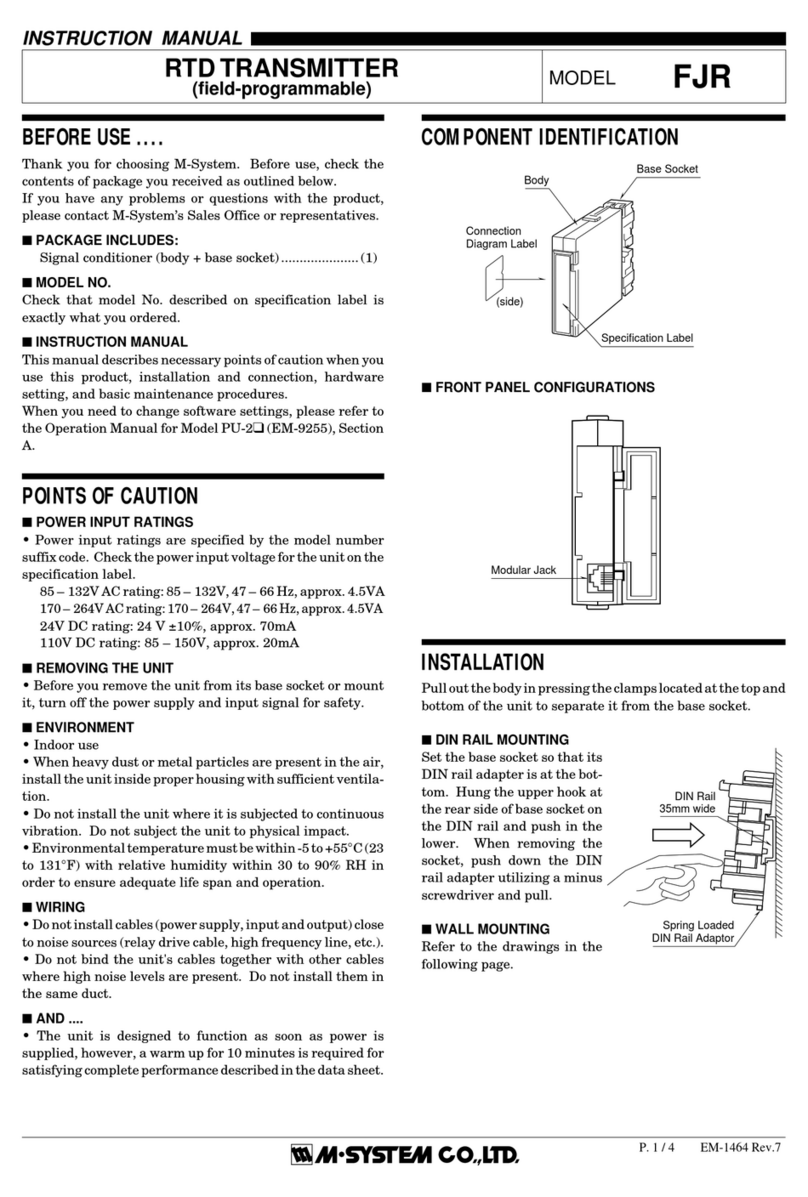
The M2XRP2 is provided with a status indicator LED which
flashes in different patterns indicating various status of its
CPU.
When it is functioning within normal parameters, the LED
flashes in a regular pattern of ON and OFF. The high levels
mean that the light is ON, while the low levels means OFF
for as shown in the figure below.
MAINTENANCE
Regular calibration procedure is explained below:
■ CALIBRATIONWarm up the unit for at least 20 minutes. Apply 0%, 25%,
50%, 75% and 100% input signal. Check that the output
signal for the respective input signal remains within accu-
racy described in the data sheet. When the output is out of
tolerance, recalibrate the unit according to the “ADJUST-
MENT PROCEDURE” explained earlier.
CHANGING I/O TYPE & RANGE
Input type and range, and output type and range can be
programmed on the Configuration Software. Additionally,
when changing the input type, hardware settings are need-
ed as explained below.
■■LEFT SIDE VIEW (with cover removed)
1
4
3
2
1
234
ON
ON OFF
OFF ON OFF
ON OFF
SW3SW1 SW2
SW4
Input Selector SW
Output Selector SW
1
2
1
2
• Output TypeOUTPUTTYPESW4-4SW4-3SW4-2SW4-10 – 20mA DC (*) OFF ON OFF OFF
-2.5 – 2.5V DC ON OFF OFF ON
-10 – +10V DC ON OFF ON OFF
■ DIP SWITCH SETTINGS (*) Factory setting
Pulse sensing and noise filter settings are invalid for RS-
422 line driver input.
• Input TypeINPUTTYPESW1-2SW1-1SW2-2SW2-1Open collector (*) OFF OFF OFF OFF
Voltage pulse OFF OFF OFF OFF
RS-422 line driver ON ON ON ON
• Pulse SensingPULSESENSINGSW3-4SW3-2Capacitor coupled *2OFF OFF
DC coupled (*) ON ON
*2. Frequency range must be 0 – 100 Hz or higher. 0 – 1
kHz or higher for sinusoidal waveform input. Frequencies
lower than ±10 Hz may be out of accuracy conformance.
• Noise FilterNOISEFILTERSW3-3SW3-1
With ON ON
W/O (*) OFF OFF
Be sure to apply the noise filter appropriate for the selected
frequency range as shown in the table below. The accuracy
may not be assured if no filter is applied.
FREQUENCYRANGENOISEFILTERTYPE0 – 10 mHz With
0 – 100 mHz With
0 – 1 Hz With
0 – 10 Hz W/O
0 – 100 Hz W/O
0 – 1 kHz W/O
0 – 10 kHz W/O
0 – 100 kHz W/O
Normal operation
Operating Mode LED Flashing Pattern
Zero adjustment
Span adjustment
Programming
Abnormal operation
80 msec.
Table of contents
Other M-system Transmitter manuals

M-system
M-system Mini-M M2TT User manual

M-system
M-system B3HU User manual

M-system
M-system 10RS User manual

M-system
M-system 10TS User manual

M-system
M-system M3LU2 User manual

M-system
M-system M5PA-CA-R User manual

M-system
M-system M3LM User manual

M-system
M-system W5 Series User manual

M-system
M-system M2EXV User manual

M-system
M-system M5XWTU User manual

M-system
M-system Mini-M M2RS User manual

M-system
M-system 10JT User manual

M-system
M-system CTS2 User manual

M-system
M-system KP User manual

M-system
M-system W2VS User manual

M-system
M-system M2LPM User manual

M-system
M-system CTH User manual

M-system
M-system Mini-M M2SP User manual

M-system
M-system W2VS User manual

M-system
M-system 10AC User manual