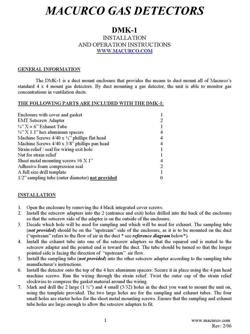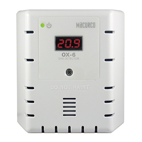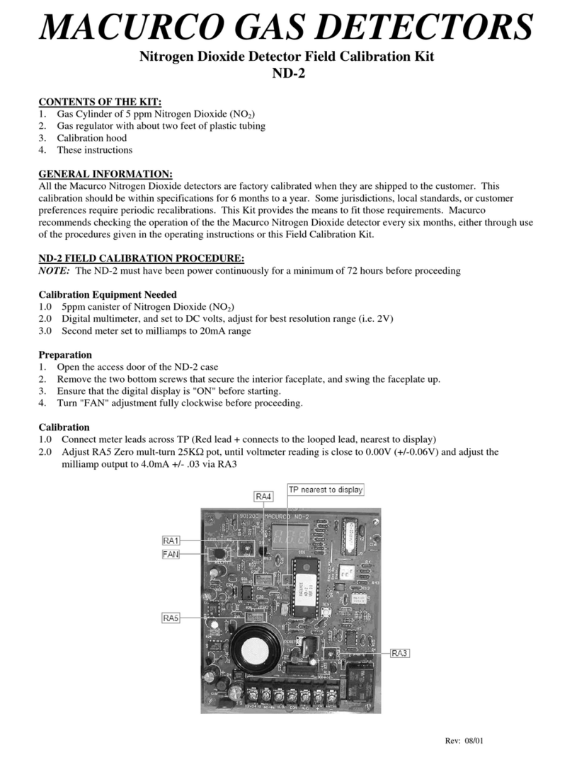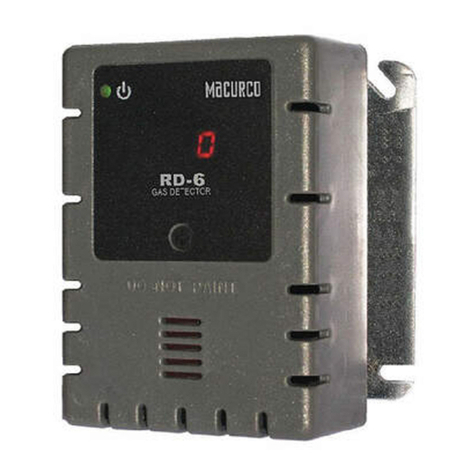
Macurco RD-xx User Manual
REV – 1.0 [34-2900-0511-7 ] 2 |Page
Table of Contents
1General Safety Information........................................................................................................................................................4
1.1 List of warnings .................................................................................................................................................................4
2Use Instructions and Limitations................................................................................................................................................5
2.1 Use For ..............................................................................................................................................................................5
2.2 Do NOT use for ..................................................................................................................................................................5
2.3 Features.............................................................................................................................................................................5
2.4 Specifications ....................................................................................................................................................................6
2.4.1 6-Series Low Voltage.....................................................................................................................................................6
2.4.2 12-Series Line Voltage...................................................................................................................................................6
3Installation and Operating Instructions .....................................................................................................................................6
3.1 Location.............................................................................................................................................................................6
3.2 Installation.........................................................................................................................................................................7
3.2.1 6-Series Low Voltage.....................................................................................................................................................7
3.2.2 12-Series Line Voltage.................................................................................................................................................12
3.3 Terminal Connection .......................................................................................................................................................17
3.3.1 6-Series Low Voltage...................................................................................................................................................17
3.3.2 12-Series Line Voltage.................................................................................................................................................17
4Operations ...............................................................................................................................................................................18
4.1 Power up .........................................................................................................................................................................18
4.2 Display turned “On” ........................................................................................................................................................18
4.3 Display turned “Off”........................................................................................................................................................19
4.4 4-20mA Loop ...................................................................................................................................................................19
4.5 Default – Factory Settings ...............................................................................................................................................20
4.5.1 Selecting Default Configuration – “dEF” .....................................................................................................................20
4.5.2 Power-Up Test Setting – “PUt” ...................................................................................................................................21
4.5.3 Display Setting – “dSP” ...............................................................................................................................................21
4.5.4 Buzzer Setting – “bUZ”................................................................................................................................................21
4.5.5 Alarm Relay Setting – “ArS” ........................................................................................................................................21
4.5.6 Alarm Relay Configuration – “Arc”..............................................................................................................................21
4.5.7 Fan Relay Setting – “FrS”.............................................................................................................................................21
4.5.8 Fan Relay Delay Setting – “Frd” ..................................................................................................................................21
4.5.9 Fan Relay Minimum Runtime Setting – “Frr”..............................................................................................................22
4.5.10 Fan Relay Latching Setting – “FrL”..........................................................................................................................22
4.5.11 Trouble Fan Setting – “tFS” ....................................................................................................................................22
4.5.12 4-20mA Output setting – “420”..............................................................................................................................22
4.5.13 Calibration Period Settings – “CAL” ..............................................................................................................................22
5Troubleshooting.......................................................................................................................................................................23
5.1 On-Board Diagnostics......................................................................................................................................................23
5.1.1 4-20mA troubleshooting.............................................................................................................................................23
5.1.2 “t” Error Codes............................................................................................................................................................23
5.2 Sensor Poisons ................................................................................................................................................................24
5.3 End-of-Life Signal.............................................................................................................................................................24
6Maintenance ............................................................................................................................................................................24
6.1 Sensor Life Reset .............................................................................................................................................................24
6.2 Cleaning...........................................................................................................................................................................25
7Testing......................................................................................................................................................................................25
7.1 Operation Test.................................................................................................................................................................25
