MAD EasyLoad EH00002 User manual

EH00002
Installation Manual
EasyLoad

EH00002 EasyLoad Installation Manual
1
MAD
Wiltonstraat 53
3095 KW Veenendaal
The Netherlands
T +31 (0) 318 586 100
mad-loadingsystems.com
info@mad-automotive.com
Version: English 04

EH00002 EasyLoad Installation Manual
2
Contents
1Introduction................................................................................................................................ 3
1.1 Definitions.......................................................................................................................... 3
1.2 Overview ........................................................................................................................... 4
2Safety............................................................................................................................. 4
3The frame .................................................................................................................................. 5
3.1 General points of attention................................................................................................ 5
3.2 Supplied mounting plates.................................................................................................. 6
3.3 Installation of the frame..................................................................................................... 7
4Electrical components............................................................................................................. 11
4.1 Door switch...................................................................................................................... 11
4.2 Control unit...................................................................................................................... 12
4.3 Power supply................................................................................................................... 12
4.3.1 General information................................................................................................. 12
4.3.2 Installation of the power cable................................................................................. 12
5Final test.................................................................................................................................. 13
5.1 General information............................................................................................. 13
5.2 Function test.................................................................................................................... 13
6Documentation ........................................................................................................................ 14
7Technical specifications EL-250.............................................................................................. 15
8Technical specifications EL-500 and EL-501.......................................................................... 17

EH00002 EasyLoad Installation Manual
3
1 Introduction
Read this manual carefully before installing the EasyLoad. The EasyLoad is a hoisting
device and it is therefore very important that the installation instructions are followed carefully to
avoid damage to the vehicle and injury to the user.
If during the installation you are in doubt or anything is unclear, or if there are any imperfections
to the product, always contact MAD.
1.1 Definitions
Orientation of the EasyLoad
The back of the EasyLoad is the side where the inner beam slides out of the outer beam.
Connecting bridge
These are the vertical plate sections on top of the EasyLoad with which the EasyLoad is attached
to the frame. For the EL-250-2xxxx and the EL-500, the three front bridges can be used. With the
EL-250-1xxxx and the EL-500-1xxx, only the first two can be used. For the EL-501, only the
second and third connecting bridges can be used. The numbering used is as follows:
Front frame
The framework in which the EasyLoad will be suspended that is mounted furthest to the front of
the vehicle.
Rear frame
The framework in which the EasyLoad will be suspended that is mounted at the back of the
vehicle. The rear frame contains a black beam.
Connecting pieces
Parts of the frame with which the frame tubes are joined together or attached to the vehicle.
Front
Back
1
2
3

EH00002 EasyLoad Installation Manual
4
1.2 Overview
2 Safety
▪Carefully read through all the instructions for use.
▪Always observe the car manufacturer's installation guidelines.
▪The EasyLoad must be installed by an authority with sufficient expertise and in
accordance with this installation manual.
▪The vehicle must have a mounted wooden loading floor.
▪Note! The EasyLoad has been developed for use in a van, in combination with the
specially developed mounting frame. All other applications are outside of the
responsibility of MAD.
Base
90° elbow
Fastening eye
Mounting plate
Fastening eye
Front frame
Base
Index bolt
90° elbow
Rear frame
Direction of travel
Outer beam
Inner beam

EH00002 EasyLoad Installation Manual
5
▪MAD is not responsible for the suspension of the EasyLoad to any mounting frame other
than the one supplied by MAD.
▪Have any damage repaired or repairs carried out by a person with the relevant expertise.
The guarantee will be void in the case of unprofessional repairs and modifications to the
EasyLoad.
▪Always put the car horizontal, apply the vehicle's parking brake and make sure the load
compartment is completely empty.
▪The weight of the EasyLoad requires that it should be lifted out of and back into the frame
by means of a lifting aid. To do this, use a transmission jack or other lifting device.
▪If such a lift is not available, the EasyLoad should be lifted or moved by at least four
people.
▪Always use straps to prevent injury and/or damage if the EasyLoad is to be lifted in or out
of the frame without a lifting aid. Pull on the tension straps alternately and evenly while
lifting. When lowering, allow the tension straps to slacken simultaneously. In all cases,
keep the EasyLoad horizontal.
▪While installing the EasyLoad, the hoisting cable should always remain under tension by
allowing the weight to hang freely above the lifting hook. This prevents the cable from
kinking and/or running off the guide wheels.
▪Always put the EasyLoad on trestles or two beams and never directly on the ground or
floor of the vehicle. This can result in damage to the hoisting cable.
▪Especially for electric vehicles, ensure that the car manufacturer's installation guidelines
are followed in the areas of the battery pack and electrical wiring.
▪When drilling in the vehicle, look out for wires which may be located behind a panel. If
there are any, divert them temporarily.
▪Remove any sharp edges after drilling and apply an anti-corrosion agent.
▪Also make sure that the wiring is not pinched or can be damaged when screwing in a bolt.
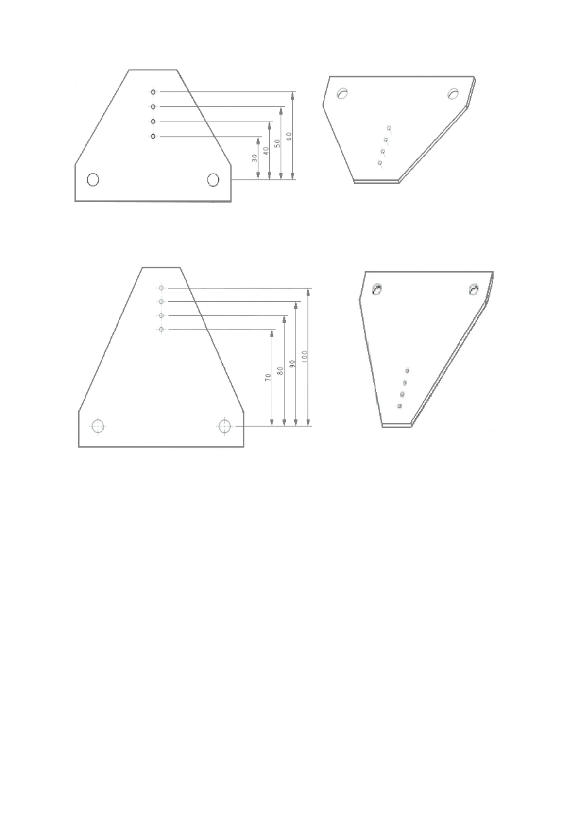
3 The frame
3.1 General points of attention
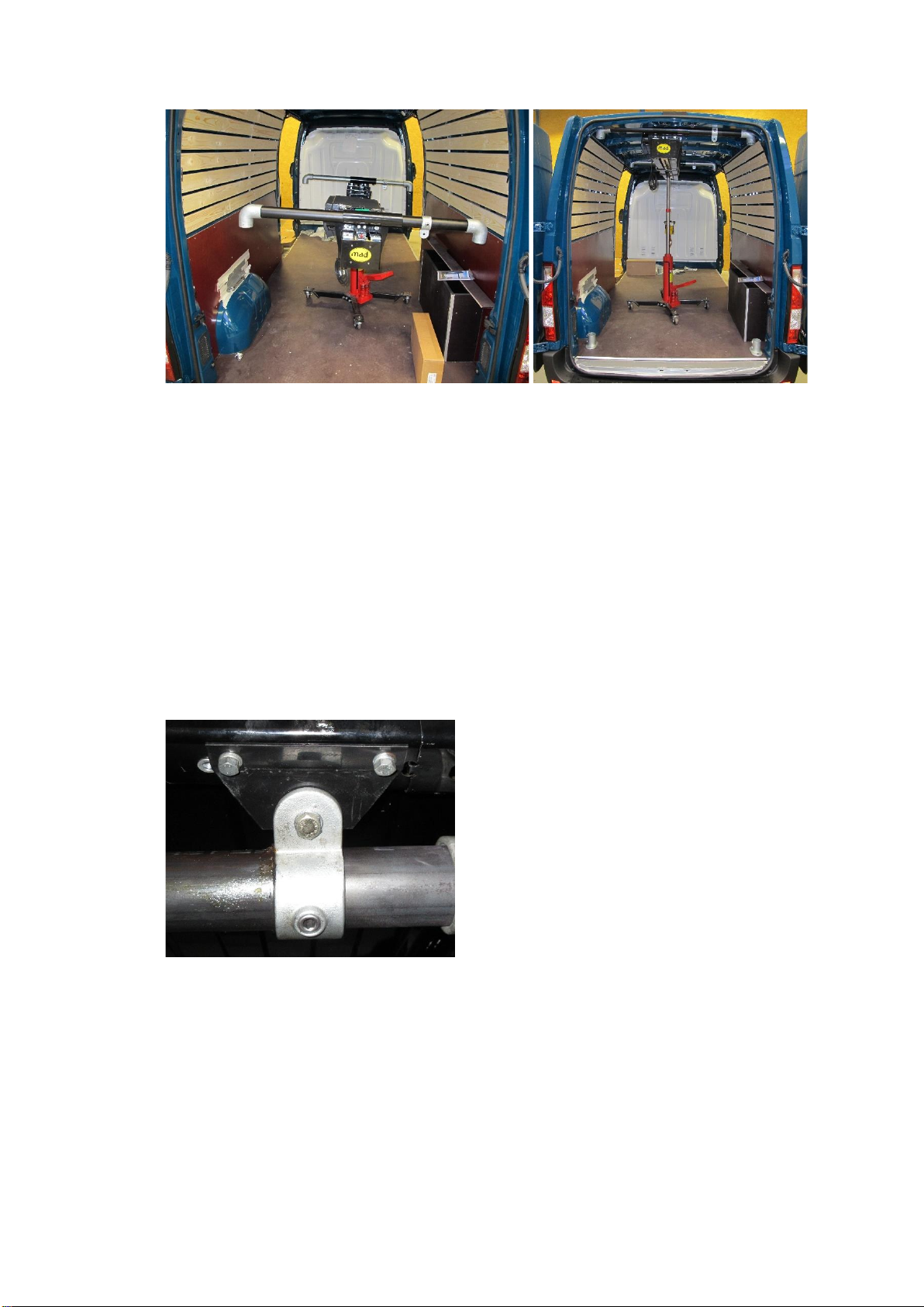
A marking must be placed on the uprights of the frame. This marking can be used to determine
whether the upright has been inserted far enough into the coupling. If the length of the frame
uprights needs to be adjusted, apply a new marking after sawing. A stripe or scratch must be
placed as a marking at a distance of "x" mm from the new cut. The distance "x" is:
•35mm, when the tube must be inserted in a coupling with one Allen bolt.
•75mm, when the tube must be inserted in a coupling with two Allen bolts.

EH00002 EasyLoad Installation Manual
6
The maximum height at which the EasyLoad will be suspended is partly determined by the
following factors:
•The height of the rear doors. When determining the height, keep a minimum of 5mm
between the underside of the rear door frame (pay attention to the door catches!) and the
top of the inner beam (top of the backplate).
•The height of the roof. Keep at least a gap of 5mm between the plastic cover of the
EasyLoad and the roof of the vehicle.
The tube with the largest wall thickness must be installed as a crossbar in the rear frame.
Always hand-tighten the elbows before lifting the pipes to prevent them from falling during
installation and causing damage or injury.
3.2 Supplied mounting plates
With each EasyLoad, four mounting plates are supplied as standard in the installation kit to attach
the top of the frame to a roof member. Depending on the type of vehicle, the kit includes 90
triangular plates and/or a 130 triangular plates. For installation of the frame in a different position,
the plates can also be ordered separately. With the plates it is possible to position the frame at
four different locations in the vehicle direction over a distance of 30 mm. By using the fastening
eyes, the location in the lateral direction is completely free to choose.
Triangular plate 90
Distance between the frame and the roof member ranging from 30 to 60 mm. MAD part number
EM86007.

EH00002 EasyLoad Installation Manual
7
Triangular 130
Distance between the frame and the roof member ranging from 70 to 100 mm. MAD part number
EM86006.
3.3 Installation of the frame
Before installing the frame, determine where the uprights are to be mounted. This depends on the
roof members (in relation to the triangular plates) and the vehicle's equipment.
1. Use a jack or forklift truck to place the EasyLoad halfway up the load compartment.
2. Mount both suspension brackets with the long ends to the right. Mount the front
suspension bracket on the first, second or third connecting bridge, depending on how the
frame is mounted. Mount the rear suspension bracket on the rear connecting bridge.
3. Slide the tube having the largest wall thickness into the rear suspension bracket.
4. Mount a 90-degree elbow onto the left-hand side of the tube.
5. Slide a fastening eye onto the right-hand side, with the lip facing downwards, and then a
90-degree elbow.
6. Hand-tighten all Allen bolts.
7. Slide the tube having the smallest wall thickness into the front suspension bracket.
8. Mount a 90-degree elbow on the left-hand side.
9. Slide a fastening eye onto the right-hand side, with the lip facing upwards, and then a 90-
degree elbow.
10. Hand-tighten all Allen bolts.
11. Jack or hoist the EasyLoad up to just below the roof.

EH00002 EasyLoad Installation Manual
8
12. Place a upright in a base. Then slide a fastening eye on the upright. Next, slide the
upright in the elbow on the left side of the rear crossbar.
13. Place another upright in a base and slide the upright in the elbow on the right side of the
rear crossbar.
14. Place the rear frame parallel to the vehicle’s door frame.
15. Position the fastening eyes for the triangular plates (see 3.2) and determine which of the
four holes should be drilled to 10.5 mm. After drilling, mount the triangular plates to the
fastening eyes of the crossmember and the upright using the M10x30 bolts supplied and
turn the fastening eyes so that the plates lie against the door frame.
16. Mark the location of the attachment points in the vehicle's door frame by taking them over
from the triangular plates. Drill 11 mm large holes for the blind rivet nuts. Beware of
cabling running through the frame!
17. Treat the holes with an anti-corrosion agent and fit the supplied blind rivet nuts, four in
total.
18. Attach the triangular panels to the door frame. Do this hand-tight so that the frame can
still be aligned.
19. Place a upright in a base. Then slide a fastening eye on the upright. Next, slide the
upright in the elbow on the left side of the front crossbar.
20. Place another upright in a base and slide the upright in the elbow on the right side of the
front crossbar.
21. Position the fastening eyes for the triangular plate (see 3.2) and determine which of the
four holes should be drilled to 10.5 mm. After drilling, mount the triangular plates to the
fastening eyes of the crossbar and upright using the M10x30 bolts supplied and turn the
fastening eyes so that the plates lie against the roof member.
22. Mark the location of the attachment points in the roof member by taking them over from
the triangular plates. Drill 11 mm large holes for the blind rivet nuts. Beware of cabling
running through the member.

EH00002 EasyLoad Installation Manual
9
23. Treat the holes with an anti-corrosion agent and fit the supplied blind rivet nuts, four in
total.
24. Fix the triangular plates. Do this hand-tight so that the frame can still be oriented.
25. Lower the jack or forklift truck.
26. Once the exact position of the frame has been determined, the holes for the bases can be
drilled. Before drilling, make sure there are no obstacles underneath the vehicle such as:
hollow spaces, fuel lines, wiring looms and door mechanisms. For 250kg: First drill the
holes with a 3 mm drill bit, then enlarge to 10.5 mm. For 500kg: First drill the holes with a
3 mm drill bit, then enlarge to 12.5 mm.
27. For 250kg: Secure the four bases with M10x50 bolts, M10 washers and M10 locknuts
(tightening torque 51 Nm).
For 500kg: Secure the four bases with M12x60 bolts, M12 washers and M12 locknuts
(tightening torque 87 Nm).
28. Now orient the whole frame properly and check that the marking on the tube is just visible
at all connecting pieces. If the marking is more than 2 mm from the edge of the
connecting piece, the tube is not inserted deeply enough into the connecting piece, as a
result of which the frame loses strength.
29. Now tighten all the Allen bolts of the frame to 40 Nm with the aid of a torque wrench. If
there are two Allen bolts in the connecting piece, then when finally tightening, always first
tighten the bolt which is furthest away from the edge of the base. Only tighten the second
bolt once the first one has been tightened to the right torque.

EH00002 EasyLoad Installation Manual
10
30. On the frame for the 500 kg versions, the bases and elbows of the front uprights must be
drilled through so that they are attached to the frame tubes by means of a bolt.
31. Drill a 8mm hole though the elbow and the left upright and place the M8x90 bolt.
32. Drill a 8mm hole though the base and the left upright and place the M8x90 bolt.
33. Repeat steps 31 and 32 for the right side.
34. Apply enough grease to the beams and check that the EasyLoad slides properly from left
to right.
35. Determine the correct location where the EasyLoad hangs when it is not being used
(entirely to the left or right).
36. Mark the holes for the index bolts. Drill the hole in the beams all the way through one wall
of the beam. Drill the holes carefully (Ø 8.5 mm - Ø 9.0 mm). For constructional reasons,
it is not allowed to drill a plurality of holes in the beams (one drilled hole / locking hole per
beam).
37. Mount the two index bolts, and test them, so that they lock the EasyLoad properly.

EH00002 EasyLoad Installation Manual
11
4 Electrical components
4.1 Door switch
The door switch ensures that the EasyLoad is switched off as soon as the doors are closed. This
prevents the battery from being drained in the event of a prolonged standstill. Please observe the
following points of attention when installing the door switch:
•To prevent damage to the doors caused by the EasyLoad, the door switch must be
mounted on the rear door that can be opened last.
•Do not place the door switch in a location where loads frequently pass by and therefore
there is a high risk of damage.
•Find a location for the switch on a flat sheet metal part in the door frame on the inside of
the vehicle, so that the switch is pressed down when the doors are closed.
•In order not to adversely affect the durability of the door switch, it should be operated as
much as possible in the longitudinal direction.
•The gap between the closed door and the door frame should be at least 9 mm.
•The supplied cable to the door switch is 2 metres long. Please take this into account while
positioning the door switch.
•Behind the panel there must be an empty space of at least 75 mm deep and it must be
accessible from the rear.
•Use the supplied bracket if the door switch cannot be mounted directly in the panel.
1. Drill a 12.5 mm hole when the door switch is mounted directly in the panel. Beware of a
possible wiring harness behind the panel!
2. Remove any burrs and treat the hole with an anti-corrosion agent.
3. Screw the steel flat nut on the switch. Measure the space between the closed door and
the doorframe. For the location of the nut, use the distance just measured plus the panel
thickness [=X], measured from the front of the housing (see photo below).
4. Install the switch through the drilled hole from the rear.
5. Screw the plastic nut onto the switch and secure the switch.
6. Check that the switch is pressed as soon as the door is closed, if not adjust the switch
again.

EH00002 EasyLoad Installation Manual
12
4.2 Control unit
The control unit can be stored in the bracket provided. The bracket is mounted on the upright of
the rear frame using two hose clamps. The location can be freely chosen by the end user. The
connecting cable is long enough to attach the bracket for the control unit to both the left and right
uprights, even if the EasyLoad is installed asymmetrically.
The connection to the EasyLoad is made by means of the 7-pin plug in the socket, on the right-
hand side on top of the EasyLoad.
Attach the curly cord to the crossbar of the rear frame using cable ties so that it does not hang in
the door opening. When doing so, keep in mind the sliding motion of the EasyLoad.
4.3 Power supply
4.3.1 General information
The EasyLoad is powered from the vehicle battery by means of a supplied power cable. This
cable is fused with a 100 or 150 Amp fuse which is located next to the battery. The length of the
power cable is determined in a left-hand drive vehicle with the corresponding location of the
battery. This is based on the following:
•A symmetrical installation of the EasyLoad.
•Frame location at the very back of the vehicle.
•Routing of the power cable on the side where the battery is located.
•Routing along the vehicle’s ceiling, in the ledge where the roof is attached to the side wall.
•If the battery is in the engine compartment, routing along the A-pillar (window-pillar). If the
battery is in the cabin, the routing is along the B-pillar (directly behind the front door).
In case of a different routing or asymmetrical placement, a different power cable may be required.
The following lengths are available (not for the EL-501):
4.3.2 Installation of the power cable
Keep the following points of attention in mind when installing the power cable:
•Make sure that the power cables are not damaged during installation by rubbing on sharp
edges or along screws.
•Protect the cables where they run through or along sheet metal to prevent damage of the
cables.
•Never route the power cables over the floor, but always along the ceiling shielded by
sheet metal or woodwork.
•Start by installing the power cables on the battery side but do not connect the cables to
the battery yet.
•It is possible to remove the connector to make it easier to route the power cable. To do
so, press the small metal lip under the contact, at the front, with a flat screwdriver and pull
the cable gently.
Description and length
Part number
Power cable 6 meter
EE08008
Power cable 8 meter
EE08009
Power cable 10 meter
EE08010

EH00002 EasyLoad Installation Manual
13
•As soon as the power cable has been fitted, immediately replace the contacts in the
connector, if they have been removed. The cable marked red in the "+" location.
•Before connecting the power cable to the battery, first connect the power cable to the
connector of the EasyLoad. Then connect the power cable to the battery terminals.
5 Final test
5.1 General information
Lift only vertically and never more than 250 kg (EL-250) 500 kg (EL-500 and EL-501). When
lifting, avoid excessive swinging.
Stop lifting as soon as there is an indication of a twisted hoisting cable, overload or other faults.
Always put the hoisting hook at the top position after use. Swinging of the hoisting hook may
cause damage to the vehicle or the load.
5.2 Function test
Each EasyLoad is thoroughly tested and adjusted by MAD after assembly. To ensure that no
defects have occurred during transport or installation, all functions must be checked before lifting
with the EasyLoad. First do this without load to protect the vehicle, EasyLoad and yourself. Follow
the steps below:
1. Check that the emergency switch is not activated.
2. Close the door that controls the door switch. The inner beam of the EasyLoad cannot be
retracted or extended and the hook cannot be lifted or lowered. If the EasyLoad can be
operated, the door switch must be adjusted again.
3. Open both rear doors and extend the inner beam of EasyLoad all the way.
4. Lower the hook all the way until the winch automatically turns off. Check whether there is
still one layer of cable on the drum of the winch. If this is not the case, the "lowering stop
switch" has to be readjusted (see the repair manual).
5. Lift the hook until the winch automatically turns off. This will happen as soon as the hook
touches both copper strips on the underside of the inner beam. Release the control button
immediately when the winch does not stop automatically. In that case, lower hook a little
bit and check the "lift stop switch" (see the repair manual).
6. Retract the inner beam of the EasyLoad all the way.
7. Activate the emergency switch. The inner beam of the EasyLoad cannot be retracted or
extended and the hook cannot be lifted or lowered. If this is not the case, please contact
MAD.
8. Attach a weight of approximately 250 kg or 500 kg to the hook of the EasyLoad and
repeat steps 3 to 6. After lifting the load (step 5), check for loose parts. Also check that
the frame is securely fastened and does not show any deformation.
9. In the event of deformation or loosening of parts during hoisting, stop immediately and
first identify and correct the cause. If in doubt, contact MAD.

EH00002 EasyLoad Installation Manual
14
10. Increase the weight to about 280 kg or 530 kg. The EasyLoad has an overload protection
and must now stop hoisting, only lowering is still possible. If hoisting is possible, then the
overload protection is not adjusted properly and must be readjusted (see the repair
manual).
6 Documentation
After the EasyLoad has been converted, the installation form in the user manual must be
completed. No guarantee can be given without this information! The user manual containing the
form must be handed over to the end user.

EH00002 EasyLoad Installation Manual
15
7 Technical specifications EL-250
EL-250-1xxx
EL-250-2xxx
Length retracted
A
1830
2230
mm
Length extended
B
3230
3630
mm
Distance hook –front of EasyLoad when retracted
C
610
610
mm
Distance hook –front of EasyLoad when extended
D
2610
3410
mm
Distance hook retracted versus extended
D-C
2000
2800
mm
Maximum reach behind the vehicle.
E
800
1200
mm
Height of beam in the door opening
160
160
mm
Weight
125
135
kg
Max. hoisting capacity
250
250
kg
Cable speed
6000
6000
mm/min
Voltage
12/24
12/24
V
Maximum power consumption
100
100
A
A
C
B
D
E

EH00002 EasyLoad Installation Manual
16
204mm
360mm
164mm
100mm
m

EH00002 EasyLoad Installation Manual
17
8 Technical specifications EL-500 and EL-501
EL-500-
1xxx
EL-500-
2xxx
EL-501-
2xxx
Length retracted
A
1830
2230
2230
mm
Length extended
B
3230
3630
3630
mm
Distance hook –front of EasyLoad when retracted
C
610
610
610
mm
Distance hook –front of EasyLoad when extended
D
2610
3410
3410
mm
Distance hook retracted versus extended
D-C
2000
2800
2800
mm
Maximum reach behind the vehicle.
E
800
1200
1200
mm
Height of beam in the door opening
160
160
160
mm
Weight
125
140
184
kg
Max. hoisting capacity
500
500
500
kg
Cable speed
3000
3000
3000
mm/min
Voltage
12
12/24
12
V
Maximum power consumption
100
100
100
A
A
C
B
D
E

EH00002 EasyLoad Installation Manual
18
204mm
360mm
164mm
100mm
440mm

EH00002 EasyLoad Installation Manual
19
MASTERING
YOUR
SAFETY AND
LOADING
SOLUTIONS.
MAD
Wiltonstraat 53
3095 KW Veenendaal
The Netherlands
T +31 (0) 318 586 100
mad-loadingsystems.com
Table of contents
Other MAD Automobile Accessories manuals
Popular Automobile Accessories manuals by other brands

Ravpower
Ravpower RP-PB063 user guide

CipherLab
CipherLab CP55 quick start guide

DIGITAL DELAY
DIGITAL DELAY Mega 475 instruction manual

Metra Electronics
Metra Electronics 99-6510 installation instructions

mPTech
mPTech RMX-140212 user manual

Bestop
Bestop WrapAround Windjammer 80041 installation instructions