manuals.online logo
Brands
  1. Home
  2. •
  3. Brands
  4. •
  5. Magliner
  6. •
  7. Truck
  8. •
  9. Magliner B4K128HM4 User manual

Magliner B4K128HM4 User manual

ASSEMBLY INSTRUCTIONS
INSTRUCCIONES PARA EL MONTAJE
www.magliner.com
Índice
Instrucciones para el montaje .....2
Lista de piezas ..............................3
Información sobre la garantía ....4
Table of Contents:
Assembly Instructions .................2
Parts List .......................................3
Warranty Information ................4
4- or 5-Bottle
Water Tray Truck
Carretilla con 4 o
5 bandejas para
botellas de agua
STEP 1: HAND TRUCK FRAME DRILLING:
If folding trays are added to a previously purchased Magliner hand truck, the frame side rails may need to be drilled as described in
the instructions. If trays are part of a complete hand truck purchased unassembled, no drilling is necessary and please skip to step 2.
Si se añaden bandejas abatibles a una carretilla de mano Magliner
comprada anteriormente, los raíles laterales de la estructura deberán
perforarse tal como se describe en las instrucciones. Si las bandejas
forman parte de una carretilla manual comprada sin montar, no será
necesario perforar. En ese caso, pase directamente al paso 2.
a. Remove the four pan head screws attaching the handle to the frame. Remove black plastic cap from top of frame. It is not necessary to
remove the handle. If the hand truck is equipped with a stair climber option, the fasteners attaching them to the frame will need to be removed.
b. Remove the red vinyl strips from the grooves on the outside of each frame side rail and replace them with the red strips furnished with the trays.
Replace the four handle bolts removed in Step a.
c. Each vinyl strip has three holes to locate the areas to be drilled. Using the strip as a guide, mark each hole location with a center punch
(see illustration)
.
Drill a 5/16” diameter hole through the hand truck side frame and repeat for all six holes.
STEP 2: LOWER TRAY ASSEMBLY
(refer to illustration):
Remove the four 5/16” hex head bolts attaching the nose plate to the hand truck
frame. Do not separate the nose plate and frame. Place the formed brackets
mounted to the folding tray over the holes in the nose plate and attach with the
four 5/16” x 2-3/8” long hex heads included with the trays and the four 5/16” hex
locknuts removed earlier.
STEP 3: UPPER AND INTERMEDIATE
TRAY ASSEMBLY
(refer to illustration):
The top two trays are assembled using 5/16” x 1-1/4” long hex head bolts and the
third tray using 5/16” x 1-3/4” long hex head bolts. Place a pivot spacer between the
hand truck frame and tray arms, pivot sleeve in the tray arm and spacer and secure
with the 5/16” hex locknuts.
Note: Lower tray on 4-bottle water truck is the same style and size as upper trays.
a. Desatornille los cuatro tornillos de cabeza redonda que unen la manija con la
estructura. Retire la tapa de plástico negra de la parte superior de la estructura.
No es necesario sacar la manija. Si la carretilla de mano tiene la opción para subir
escaleras, deberán quitarse los cierres que la atan a la estructura.
b. Quite las tiras de vinilo rojo de la ranura de la parte exterior de cada raíl
lateral de la estructura y cámbielas por las tiras rojas suministradas con las
bandejas. Sustituya los cuatro tornillos sacados en el paso a.
c. Cada tira de vinilo tiene tres agujeros que señalan las zonas que deberán
perforarse. Utilizando las tiras como guía, marque cada ubicación del agujero
con un punzón
(ver dibujo)
. Perfore un agujero de 5/16” de diámetro en el
marco lateral de la carretilla de mano y repita esta acción con los seis agujeros.
PASO 2: MONTAJE DE LA BANDEJA INFERIOR
(ver la ilustración)
Desatornille los cuatro tornillos de cabeza hexagonal de 5/16” que unen la placa delantera con la estructura de la carretilla de mano. No separe la placa
delantera de la estructura. Coloque los soportes formados montados en la bandeja abatible sobre los agujeros de la placa delantera y únalos con las cuatro
cabezas hexagonales de 5/16” x 2-3/8” de longitud incluidas con las bandejas y las cuatro contratuercas hexagonales de nylon de 5/16” retiradas anteriormente.
PASO 3: MONTAJE DE LA BANDEJA SUPERIOR E INTERMEDIA
(ver la ilustración)
Las dos bandejas superiores se han unido con tornillos de cabeza hexagonal de 5/16” x 1-1/4” de longitud y la tercera bandeja (más baja intermedia) con
tuercas de cabeza hexagonal de 5/16” x 1-3/4” de longitud. Coloque un separador pivotante entre la estructura de la carretilla de mano y los brazos de la
bandeja, un manguito pivotante en el brazo y el separador de la bandeja y asegúrelos con contratuercas hexagonales de nylon de 5/16”.
Nota: La bandeja inferior de la carretilla con 4 bandejas es el mismo estilo y tamaño de las bandejas superiores
5-3/32’’
REF.
16-7/32’’
REF.
27-15/32’’
REF.
SPACER SLEEVE BOLT
UPPER TRAY
UPPER KIT - PACK 1 - (#87501)
SPACER SLEEVE BOLT
UPPER TRAY
UPPER KIT - PACK 2 - (#87502)
LOWER KIT - PACK 3 - (#87503)
BRACKET
BOLT
PASO 1: PERFORACIÓN DE LA ESTRUCTURA
DE LA CARRETILLA MANUAL
REMARKS:
The hex bolts and nuts attaching the folding trays should be adjusted
to hold the trays in the vertical position when not being used, and
still allow the trays to be moved to the horizontal position. Periodic
adjustment may be necessary.
The proper torque for the 1/4” handle bolts is 50-60 in. lbs., and the
5/16” nose plate bolts is 120-140 in. lbs. If you do not have a torque
wrench available, tighten securely, but do not over tighten.
• For stability, a 12” deep nose is required. If a shorter nose is used, the truck
may tip, resulting in loss of load, property damage, and/or personal injury.
• Full bottles placed on the upper trays only may reduce truck stability and
the truck could tip forward, resulting in loss of load.
• Load the truck from the bottom-to-the-top, and unload from the top-to-
the-bottom, placing empty containers in the upper trays.
• Place the truck on a level surface prior to loading or unloading.
• To avoid flipping the load; ease your truck back gently when getting
underway and ease it gently forward when returning the truck to an
upright position.
• Avoid obstructions in your path.
• Proceed slowly around corners.
• When approaching stairs, curbs, etc. align the truck wheels prior to
ascending or descending.
•
Se necesita una parte delantera de 12” de profundidad por motivos de
estabilidad. Si se utiliza una parte delantera más corta, la carretilla se
podría desequilibrar y la mercancía podría caer, se podría dañar el aparato
y/o a una persona.
•
Sólo las botellas llenas colocadas en las bandejas superiores podrían
reducir la estabilidad de la carretilla e inclinarlo hacia adelante, por lo que
podría caer la carga.
•
Cargue la carretilla de arriba a abajo y descárguela de abajo a arriba,
colocando los contenedores vacíos en las bandejas superiores.
•
Coloque la carretilla en un nivel de superficie previo a la carga o descarga.
•
Para evitar la caída de la carga, mueva la carretilla hacia atrás con cuidado
al pasar por zonas bajas y mueva la carretilla hacia adelante con cuidado
al devolver la carretilla a la posición vertical.
•
Evite tener obstáculos en su camino.
•
Tenga cuidado en las esquinas.
•
Al acercarse a escaleras, bordillos, etc., alinee las ruedas de la carretilla
antes de bajar o subir.
PART NO. QTY. DESCRIPTION
TRAY INSTALLATION PACKS
NÚMERO CANTIDAD DESCRIPCIÓN DE PIEZA
PAQUETES DE INSTALACIÓN DE BANDEJAS
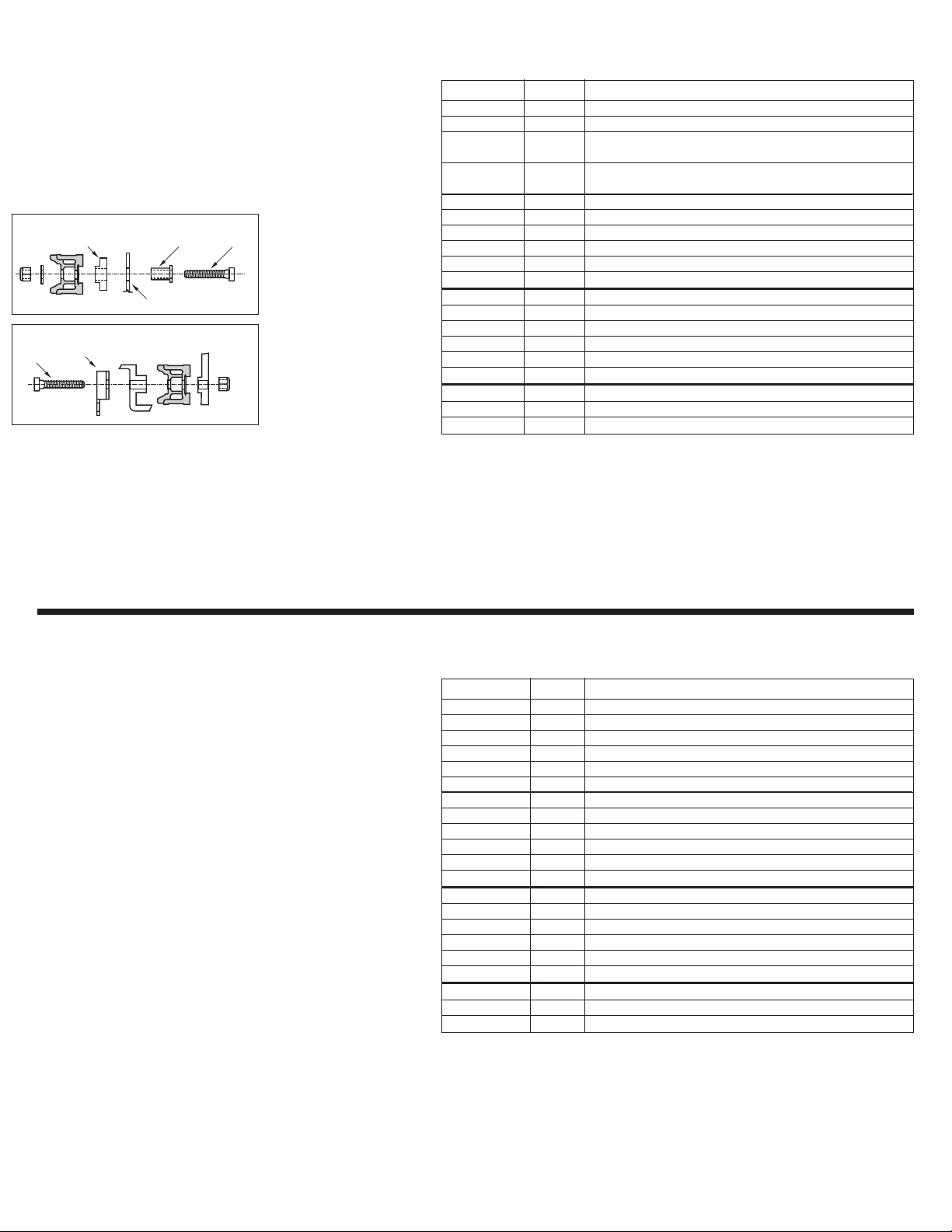
SPACER SLEEVE BOLT
UPPER TRAY
UPPER KIT - PACK 1 - (#87501)
SPACER SLEEVE BOLT
UPPER TRAY
UPPER KIT - PACK 2 - (#87502)
LOWER KIT - PACK 3 - (#87503)
BRACKET
BOLT
SPACER SLEEVE BOLT
UPPER TRAY
UPPER KIT - PACK 1 - (#87501)
SPACER SLEEVE BOLT
UPPER TRAY
UPPER KIT - PACK 2 - (#87502)
LOWER KIT - PACK 3 - (#87503)
BRACKET
BOLT
TOOLS REQUIRED
• (1) MOTORIZED DRILL
• (1) 5/16" DIA. DRILL BIT
• (1) 7/16" COMBINATION
WRENCH
• (2) 1/2" COMBINATION
WRENCH
• (1) #3 PHILLIPS HEAD
SCREWDRIVER
• (1) CENTER PUNCH
• (1) HAMMER
NOTAS:
Los tornillos y tuercas hexagonales que unen las bandejas abatibles
deberían ajustarse para que las bandejas se mantengan en posición
vertical cuando no se utilicen y que permitan mover las bandejas
en posición horizontal. Es posible que sea necesario realizar ajustes
periódicamente.
El par de torsión adecuado
para los tornillos de la manija
de 1/4” es de 50-60 in. lbs. y los
tornillos de la placa delantera
de 5/16” es de 120-140 in. lbs. Si
no dispone de una llave inglesa,
apriete los tornillos de manera
segura, sin exceso.
HERRAMIENTAS
NECESARIAS
•
(1) TALADRADORA
•
(1) PIEZA TALADRADORA DE
5/16” DE DIÁMETRO
•
(1) LLAVE INGLESA
COMBINADA 7/16”
•
(2) LLAVE INGLESA
COMBINADA 1/2”
•
(1) #3 DESATORNILLADORES
DE CABEZA PHILLIPS
•
(1) PUNZÓN
•
(1) MARTILLO
301444 OR 301438 1 BW TRAY INSTALLATION PACK consists of items below:
301434 3 TOP 3 TRAYS
87501 2 FASTENER PACK #1
301440 1 BOTTOM TRAY, WITH MOUNTING BRACKETS AND HARDWARE
(5-TRAY TRUCK)
301436 1 BOTTOM TRAY, WITH MOUNTING BRACKETS AND HARDWARE
(4-TRAY TRUCK)
87501 2 FASTENER PACK #1 (FOR TOP 2 TRAYS) CONSISTS OF:
80012 2 5/16” X 1-1/4” LONG HEX HEAD SCREW
80676 2 5/16” HEX LOCKNUT
80761 2 5/16” FLAT WASHER
301435 2 TRAY PIVOT SPACER – BLACK
301461 2 TRAY PIVOT SLEEVE, 1/2” LONG
87502 1 FASTENER PACK #2 (for tray #3) consists of:
80014 2 5/16” X 1-3/4” LONG HEX HEAD SCREW
80676 2 5/16” HEX LOCKNUT
80761 2 5/16” FLAT WASHER
301435 2 TRAY PIVOT SPACER – BLACK
301461 2 TRAY PIVOT SLEEVE, 1/2” LONG
87503 1 FASTENER PACK #3 (for bottom tray) consists of:
80051 4 5/16” X 2-3/8” LONG HEX HEAD SCREW
80676 4 5/16” HEX LOCKNUT
301444 O 301438 1 PAQUETE DE INSTALACIÓN DE BANDEJA BW consta de:
301434 3 3 BANDEJAS SUPERIORES
87501 2 PAQUETE DE CIERRES #1
301440 1 LA BANDEJA DEL FONDO CON SOPORTES DE MONTAJE
(CARRETILLA DE 5 BANDEJAS)
301436 1 LA BANDEJA DEL FONDO CON SOPORTES DE MONTAJE
(CARRETILLA DE 4 BANDEJAS)
87501 2 PAQUETE DE CIERRES #1 (para 2 bandejas superiores) consta de:
80012 2 TORNILLOS CABEZA HEXAGONAL DE 5/16” X 1-1/4” DE LONGITUD
80676 2 CONTRATUERCA HEXAGONAL DE 5/16”
80761 2 ARANDELA PLANA DE 5/16”
301435 2 ESPACIADOR PIVOTANTE BANDEJA - NEGRO
301461 2 MANGUITO PIVOTANTE BANDEJA DE 1/2” DE LONGITUD
87502 1 PAQUETE DE CIERRES #2 (para bandeja #3) consta de:
80014 2 TORNILLOS CABEZA HEXAGONAL DE 5/16” X 1-3/4” DE LONGITUD
80676 2 CONTRATUERCA HEXAGONAL DE 5/16”
80761 2 ARANDELA PLANA DE 5/16”
301435 2 ESPACIADOR PIVOTANTE BANDEJA - NEGRO
301461 2 MANGUITO PIVOTANTE BANDEJA DE 1/2” DE LONGITUD
87503 1 PAQUETE DE CIERRES #3 (para bandeja inferior) consta de:
80051 4 TORNILLOS CABEZA HEXAGONAL DE 5/16” X 2-3/8” DE LONGITUD
80676 4 CONTRATUERCA HEXAGONAL DE 5/16”
B7981 Revised 4/14 © Copyright 2005-2014 Magline, Inc.
Magline, Inc.
1205 W. Cedar Street • Standish, MI 48658 USA
1-800-MAGLINE (624-5463) • (989) 512-1000 (fuera de USA & Canada)
www.magliner.com
Magline, Inc.
1205 W. Cedar Street • Standish, MI 48658 USA
1-800-MAGLINE (624-5463) • (989) 512-1000 (outside U.S. & Canada)
www.magliner.com

This manual suits for next models

1

Other Magliner Truck manuals

Magliner CooLift CTA43 User manual

Magliner

Magliner CooLift CTA43 User manual

Magliner HRK User manual

Magliner

Magliner HRK User manual

Magliner C5 User manual

Magliner

Magliner C5 User manual

Magliner MTA2-L User manual

Magliner

Magliner MTA2-L User manual

Magliner MAG220 User manual

Magliner

Magliner MAG220 User manual

Magliner GEMINI Sr. User manual

Magliner

Magliner GEMINI Sr. User manual

Magliner 111-AA-815 User manual

Magliner

Magliner 111-AA-815 User manual

Magliner 170 Ergo User manual

Magliner

Magliner 170 Ergo User manual

Magliner Y-Cable User manual

Magliner

Magliner Y-Cable User manual

Magliner GEMINI XL User manual

Magliner

Magliner GEMINI XL User manual

Magliner C5 User manual

Magliner

Magliner C5 User manual

Popular Truck manuals by other brands

Lionel VISION Line owner's manual

Lionel

Lionel VISION Line owner's manual

RAM Commercial 2018 PROMASTER user guide

RAM Commercial

RAM Commercial 2018 PROMASTER user guide

Volvo VNL 780 Operator's manual

Volvo

Volvo VNL 780 Operator's manual

Komatsu HD785-5 Operation & maintenance manual

Komatsu

Komatsu HD785-5 Operation & maintenance manual

freightliner Custom Classic MT45 2022 Maintenance manual

freightliner

freightliner Custom Classic MT45 2022 Maintenance manual

Trane Thermo King TriPac EVOLUTION installation manual

Trane

Trane Thermo King TriPac EVOLUTION installation manual

Blue Giant EPJ-30 owner's manual

Blue Giant

Blue Giant EPJ-30 owner's manual

ED EPT20-15EHJ Service manual

ED

ED EPT20-15EHJ Service manual

freightliner NEW CASCADIA 2016 Driver manual

freightliner

freightliner NEW CASCADIA 2016 Driver manual

Steren k-688 instruction manual

Steren

Steren k-688 instruction manual

Hyster B917 Service & repair manual

Hyster

Hyster B917 Service & repair manual

Taylor-Dunn Tiger TC50E Operator's manual

Taylor-Dunn

Taylor-Dunn Tiger TC50E Operator's manual

Still EXU-H-18 Original instructions

Still

Still EXU-H-18 Original instructions

LGMG MT86H Operation and maintenance manual

LGMG

LGMG MT86H Operation and maintenance manual

AUSA D 201 RH Operator's manual

AUSA

AUSA D 201 RH Operator's manual

Westfalia 84 68 43 instruction manual

Westfalia

Westfalia 84 68 43 instruction manual

Komatsu HM400-1 manual

Komatsu

Komatsu HM400-1 manual

DAF LF45 Series manual

DAF

DAF LF45 Series manual

manuals.online logo
manuals.online logoBrands
  • About & Mission
  • Contact us
  • Privacy Policy
  • Terms and Conditions

Copyright 2025 Manuals.Online. All Rights Reserved.