3
Item Description Qty. Part No.
A Nose plate assembly 1 301482
B Frame 1 3014680
C Roll pin for axle 4 190104
D Axle - 18" long 1 22101
E Shaft collar - 5/8" ID 2 83051
F Rear support brace 1 301475
G RH wheel bracket 1 210100
H LH wheel bracket 1 210101
I Hex head cap screw - 5/16"-18 x 1-1/4" long 4 80012
J Hex lock nut - 5/16"-18 4 80676
KRear support mount for 10" wheel option - 12.6" long 1 301483
Use a workbench or table of convenient height and place all components in view and within reach.
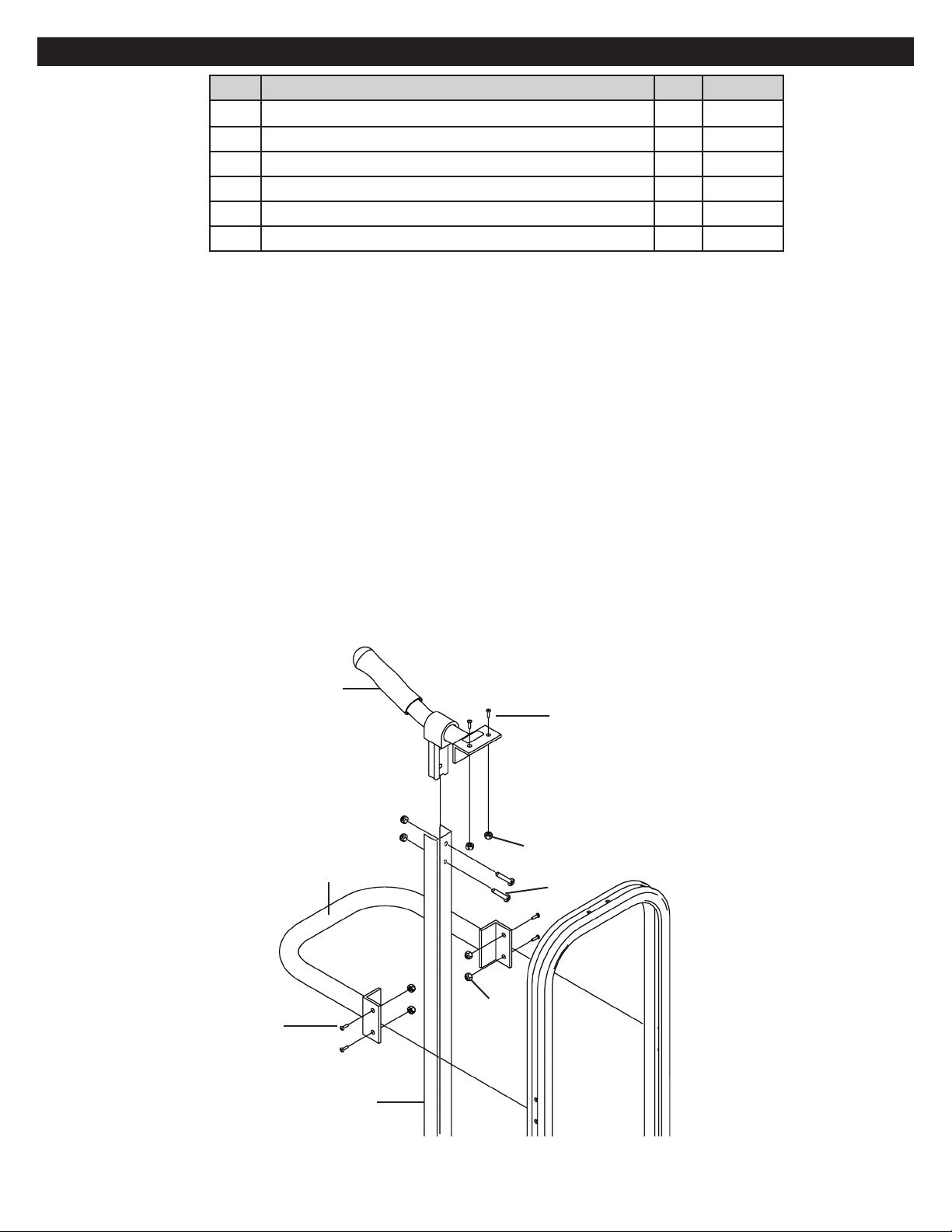
1. Assemble hand truck frame, nose assembly and RH wheel bracket.
a. Slide the frame (B) down and over the RH and LH nose mounting brackets on the nose plate assembly
(A), temporarily inserting one 5/16"-18 x 1-1/4" long hex head screw (I) through the upper hole of the LH nose
mounting bracket and the upper frame mounting hole.
b. Position and attach the RH wheel bracket (G) to the outside of the frame leg, aligning the mounting holes with the
frame and RH nose mounting bracket holes. Insert two 5/16"-18 x 1-1/4" long hex head screws (I) through the
wheel bracket mounting holes and thread on one 5/16"-18 hex lock nut (J) (see Figure 3). NOTE: Do not tighten
securely at this time.
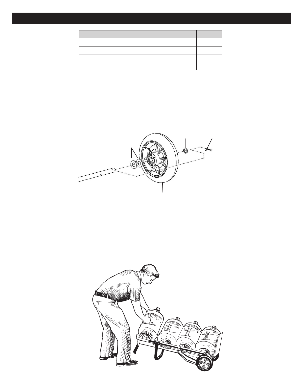
2. Install roll pin and shaft collars.
a. Install the first roll pin (C) in the rear support mount (K), tapping lightly with hammer to center the pin on the
support mount (see Figure 4).
b. Slide one shaft collar (E) onto the support mount (K). Next slide on the rear support brace (F) followed by the
second shaft collar (E) (see Figure 4). Do not tighten the shaft collars against the support mount at this time.
c. Install one roll pin (C) in the axle (D), tapping lightly with hammer to center the pin on the axle.
3. Assemble LH wheel bracket to hand truck frame.
a. Insert the support mount (K) (the end with the roll pin in place) through the lower axle hole in the RH wheel bracket
(G) (labeled x on Figure 3). NOTE: Rotate support mount until roll pin "locks" into position in the wheel bracket.
b. Insert the axle (D) (the end with the roll pin in place) through the upper axle hole in the RH wheel bracket (G)
(labeled y on Figure 3). NOTE: Rotate axle until roll pin "locks" into position in the wheel bracket.
c. Position and attach the LH wheel bracket (H), sliding it over the axle and support mount to the outside of the frame
leg. Insert one 5/16"-18 x 1-1/4" long hex head screw (I) through the bottom mounting hole of the wheel bracket,
frame and nose mounting bracket; then thread on one 5/16"-18 hex lock nut (J). Remove the upper 5/16"-18 x
1-1/4" long screw and re-install through the upper mounting hole of the wheel bracket; thread on one 5/16"-18 hex
lock nut (see Figure 3). NOTE: Do not tighten securely at this time.
4. Install the other roll pins (C) in the support mount and axle, tapping lightly with hammer to center.
ASSEMBLE THE NOSE, WHEEL BRACKETS AND AXLE TO THE FRAME - 10" WHEELS ONLY
TOOLS REQUIRED
• 1/2” DEEP WELL SOCKET
AND RATCHET
• 7/16” DEEP WELL SOCKET
AND RATCHET
• 5/32 ALLEN WRENCH
• #2 PHILLIPS SCREWDRIVER
• HAMMER
• PLIERS
K
E
E
C
F
Figure 4
C
F
A
EB
D
I
H
G
I
J
x
C
Figure 3
y


 Operator's manual")