Fnirsi DSO-TC2 User manual

DSO-TC2

1、Safety Instructions 01
1211
15
13
7、Extended Testing Capabilities 8、Firmware Upgrade
9、Common Problem 10、Note
3.1 FNIRSI DSO-TC2 equipment parameters 02
3.2 Specifications of oscilloscope mode 02
3.3 Technical parameters of transistor detector 03
3、Technical Parameter
4.1 Button function 04 4.2 Transistor test socket 05
4.3 Signal interface 06 4.4 Charging interface 07
4、Button & Interface
5、Oscilloscope Mode Features
5.1 TFT display 07
5.3 Oscilloscope probe 08
5.2 Real-time measurement parameters 08
6.1 Operation and TFT display 09
6.2 Zone 1-2-3 test seat 09
6.3 Zone K-A-A test seat 10
6.4 Infrared remote control decoding 10
6.5 System settings 11
6、Transistor Test Mode Function
11、Production Information 15
01
2、Product Introduction
"Oscilloscope" mode to test the signal waveform of the circuit
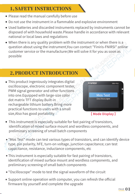
This product ingeniously integrates digital
oscilloscope, electronic component tester,
PWM signal generator and other functions
into one.Equipped with large-size color
dot matrix TFT display.Built-in
rechargeable lithium battery.Bring more
practical functions to users with a small
size,Also has good portability
"Mos Test" mode can test various types of transistors, and can identify device
type, pin polarity, hFE, turn-on voltage, junction capacitance; can test
capacitance, resistance, inductance components, etc
This instrument is especially suitable for fast pairing of transistors,
identification of mixed surface mount and wordless components, and
preliminary screening of small batch components
【 Mode Display 】
PAGE
Please read the manual carefully before use
Do not use the instrument in a flammable and explosive environment
Used batteries and discarded instruments replaced by instruments cannot be
disposed of with household waste.Please handle in accordance with relevant
national or local laws and regulations
When there is any quality problem with the instrument or when there is a
question about using the instrument,You can contact "Finiris-FNIRSI" online
customer service or the manufacturer,We will solve it for you as soon as
possible
This instrument is especially suitable for fast pairing of transistors,
identification of mixed surface mount and wordless components, and
preliminary screening of small batch components
Support online operation with computer, you can refresh the official
firmware by yourself and complete the upgrade
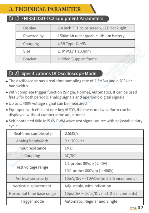
The oscilloscope has a real-time sampling rate of 2.5MS/s and a 200kHz
bandwidth
With complete trigger function (Single, Normal, Automatic), it can be used
freely for both periodic analog signals and aperiodic digital signals
Up to ±400V voltage signal can be measured
Equipped with efficient one-key AUTO, the measured waveform can be
displayed without cumbersome adjustment
Self-contained 80kHz /5.0V PWM wave test signal source with adjustable duty
cycle
【3.1】 FNIRSI DSO-TC2 Equipment Parameters
【3.2】 Specifications Of Oscilloscope Mode
Display
Powered by
Charging
Size
Bracket
2.4 inch TFT color screen, LED backlight
1500mAh rechargeable lithium battery
USB Type-C,+5V
L79*W31*H103mm
Hidden Support frame
Real-time sample rate
Analog bandwidth
Input resistance
Coupling
Vertical sensitivity
Test voltage range
Vertical displacement
Horizontal time base range
Trigger mode
1MΩ
2.5MS/s
0 ~200kHz
AC/DC
10mV/Div ~ 10V/Div (in 1-2-5 increments)
1:1 probe: 80Vpp (±40V)
10:1 probe: 800Vpp (±400V)
Adjustable, with indication
10μs/Div ~ 500s/Div (in 1-2-5 increments)
Automatic, Regular and Single
PAGE

【3.3】 Technical Parameters Of Transistor Detector
This instrument can automatically identify and measure various
transistors.Including NPN and PNP transistors, N-channel and P-channel field
effect transistors, junction field effect transistors, diodes, double diodes,
thyristors, etc.,and passive components such as resistors, inductors,
capacitors, etc
Automatic detection of pin definitions
It can automatically parse the infrared code of the NEC protocol
Other functional modes: including circuit continuity test, 0~16V input voltage
measurement, PWM output, 0~24V Zener diode measurement, DS18B20
temperature sensor measurement, DHT11 temperature and humidity sensor
measurement, etc
Trigger type
Trigger level
Waveform freeze
Automatic
measurement
PWM output
Rising edge, falling edge
Adjustable, with indication
Yes (HOLD function)
Maximum, minimum, average, rms, peak-to-peak,
frequency, period, duty cycle
FRQ: 0~80KHz, Duty cycle: 0~100%, Amplitude: 5.0V
Triode
Category Scope Technical Parameter
*
Forward voltage
drop <5V
Forward Voltage Drop, Junction Capacitance,Reverse
Leakage Current ②
Diode
JFET
IGBT
MOSFET
0.01~4.5V
0.01~24V
(1-2-3 test area) forward voltage drop, reverse
breakdown voltage
(K-A-A test area) reverse breakdown voltage
Gate capacitance Cg, drain current Id at Vgs, protection
diode forward voltage drop Uf ④
Turn-on voltage Vt, gate capacitance Cg, drain-source
resistance Rds, protection diode forward voltage drop
Uf ④
Drain current Id at Vgs, protection diode forward
voltage drop Uf ④
Zener diode
FET③
PAGE
Magnification hfe, base-emitter voltage Ube, Ic/Ie,
collector-emitter reverse cut-off current Iceo, Ices,
protection diode forward voltage drop Uf ①

【4.1】 Button Function
Turn-on voltage
<5V, gate trigger
current <6mA
*
*
25pF~100mF
0.01Ω~50MΩ
10uH~1000uH
0.1~4.5V
0~16V
1.5kHz~9.99MHz
NEC protocol
infrared code
Gate voltage
Capacitance value, loss factor Vloss ⑤
resistance
Inductance value, DC resistance ⑥
Voltage value, positive and negative polarity
Voltage value
Temperature
Humidity
*
Display user code and data code, and display the
corresponding infrared waveform
SCRS
Triac
Capacitance
Resistance
Inductance
Battery
Input voltage
DS18B20
DHT1
PWM output
Infrared remote
control decoding
Note ① : Ices, Iceo, Uf are displayed only when valid
Note ②: Junction capacitance and reverse leakage current are displayed only when valid
Note ③: The turn-on or turn-off voltage of the FET must be less than 5V
Note ④: Displayed only when there is a protection diode
Note ⑤: Vloss is only displayed when valid
Note ⑥: Two-pin component and inductance measurement when the resistance is less than 2.1kΩ
TFT display
Ocking IC seat
Power
Type-C
Charging Interface
Locking lever
Enter menu/
Automatic adjustment
Indicator light
Infrared test
receiving window
Move up
Start/Pause test
Move down
Confirm selection
Integrated foldable stand
PAGE
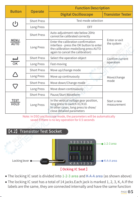
The locking IC seat is divided into 1-2-3 area and K-A-A area (as shown above)
The locking IC seat has a total of 14 jacks.Each jack is marked 1, 2, 3, K, A.If the
labels are the same, they are connected internally and have the same function
Note: In DSO oscilloscope mode, the parameters will be automatically
saved if there is no key operation for 0.5 seconds
Button Function Description
Digital Oscilloscope
OFF
Auto-adjustment rate below 20Hz
cannot be calibrated correctly
Transistor Tester
Enter or exit
the system
Confirm current
operation
Move/change
mode
Start a new
measurement
Enter the calibration confirmation
interface - press the OK button to enter
the calibration mode(long press AUTO
again to cancel the calibration)
Select the operation object
Fast-moving
Move up/change mode
Move up continuously
Move down/Change mode
Move down continuously
Operate
Long Press
Short Press
Long Press
Short Press
Long Press
Short Press
Long Press
Short Press
Long Press
Short Press
Long Press
Short Press Pause/Start Waveform
In the vertical voltage gear position,
long press to switch X1/X10.
In other cases, long press to show/
close detailed parameters
Test mode selection
【 Ocking IC Seat 】
1-2-3 area
K-A-A areaLocking lever
【4.2】 Transistor Test Socket
PAGE

There is a locking lever on the left end of the socket.The socket is relaxed
when standing up.Insert or remove the component under test at this
time.When turned down, the socket is locked and tested
After inserting the element under test and locking.Press 【TEST】 button to
test.The tester automatically identifies the pin name of the component and
the test point where it is located, and displays it on the screen
When testing 2-pin components, it can be inserted into any two holes with
different labels in the 1-2-3 area.No need to distinguish
When testing 3-pin components, it can be inserted into any three holes with
different numbers in the 1-2-3 area.No need to distinguish
The K-A-A jack is a special area for withstand voltage testing.There is about
30V DC high voltage inside.K is positive and A is negative. It is used for
withstand voltage test and cannot be mixed.The positive electrode of the
component under test, such as the Zener diode, is inserted into A, and the
negative electrode is inserted into K
1. Discharge the capacitor before measuring the capacitor,
otherwise it may burn the instrument
2. Live test is not recommended
NOTE !
For wired testing, you should use test wire with MCX plugs to
connect to the instrument
There are 3 MCX coaxial sockets evenly distributed on the top surface, and
their outer rings are connected to the same ground.The uses are:
【IN(0~16V)】⸺Test voltage input port, the core wire is positive, and the
maximum measured voltage cannot exceed DC16V
【PWM】⸺PWM square wave signal output port, output square wave signal
with adjustable pulse width
【DSO】⸺oscilloscope test signal input port, the maximum measurement
voltage shall not exceed ±40V (probe X10 shall not exceed ±400V)
【 Signal Interface 】
【4.3】 Signal Interface
PAGE
In order to avoid static electricity damage to the instrument
or the component under test, do not use it while charging
NOTE!
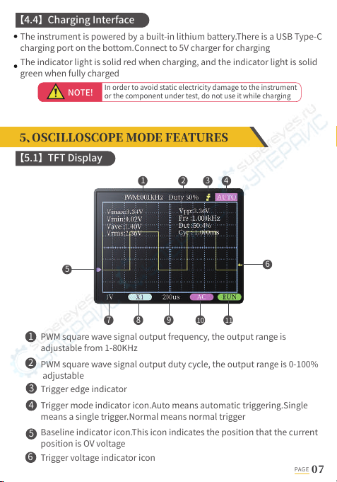
PWM square wave signal output frequency, the output range is
adjustable from 1-80KHz
PWM square wave signal output duty cycle, the output range is 0-100%
adjustable
Trigger edge indicator
Trigger mode indicator icon.Auto means automatic triggering.Single
means a single trigger.Normal means normal trigger
Baseline indicator icon.This icon indicates the position that the current
position is OV voltage
Trigger voltage indicator icon
1
2
3
4
5
6
5
1
7 8 910
2 3 4
11
6
【4.4】 Charging Interface
【5.1】 TFT Display
PAGE
The instrument is powered by a built-in lithium battery.There is a USB Type-C
charging port on the bottom.Connect to 5V charger for charging
The indicator light is solid red when charging, and the indicator light is solid
green when fully charged
Long press the 【TEST】 button to display/hide the 8 real-time measurement
parameters displayed in the upper part of the screen:
Vertical sensitivity.Indicates the voltage represented by one grid in the
vertical direction
1X/10X mode indicator icon.This must be consistent with the 1X/10X switch
setting on the probe handle.If the probe is in 1X gear, then the oscilloscope
should also be set to 1X gear.1X measures ±40V voltage, 10X measures
±400V voltage
Horizontal time base.Indicates the length of time represented by one grid in
the horizontal direction
Input coupling mode indicator icon.AC stands for AC coupling.DC stands for
direct current coupling
Run pause indicator.RUN means run.STOP means pause
7
8
9
10
11
Vmax = Maximum voltage
Vmin = Minimum voltage
Vave = Average Voltage
Vrms = RMS voltage
Vpp = Peak-to-Peak Voltage
Fre = Frequency
Dut = Positive duty cycle
Cyc = Cycle
【5.2】 Real-time Measurement Parameters
【5.3】 Oscilloscope Probe
NOTE!
Note: When the waveform amplitude exceeds the screen,these
measurements will produce large errors
PAGE
Insert the oscilloscope probe with the MCX plug into the top 【DSO】 jack.First
adjust the attenuation file on the probe.Clip the probe's ground to the
"reference ground" of the circuit under test
The probe tip or hook is securely connected to the node under test in the
circuit.Observe the voltage waveform of the measured point on the screen
1.The attenuation ratio of the probe should match the voltage of the
signal under test.Please do not measure voltage signals that exceed
the maximum range
2.When measuring the signal exceeding the safe voltage, the human
body should not touch the exposed metal part of the instrument to
avoid electric shock injury

Operating
status Internal supply
voltage
Step 1:
Step 2:
(1)Protection diodes inside bipolar transistors and MOSFETs can be detected
(2)Measure the current amplification factor (hFE) of bipolar transistors and
the turn-on voltage (Uf) of the emitter junction.Darlington transistors can
be identified by high threshold voltage and high current amplification factor
(3)The parameters Iceo, Ices and Uf of the measuring triode will only be
displayed when the measurement is valid
(4)The diode's equivalent capacitance C and reverse leakage current Ir are
displayed only when the measurement is valid
(5)The turn-on or turn-off voltage of the FET should be less than 5V.Other
wise, the measured results are only its equivalent parameters (diodes,
capacitors, etc.)
【6.1】 Operation And TFT Display
【6.2】 Zone 1-2-3 Test Seat
PAGE
After entering this mode, the test will start automatically.Displays the internal
Lithium battery voltage in the "Testing" state
After the test results come out, you can click the 【TEST】 button to perform
the next test at any time
After inserting the
component to be tested,
press the locking lever to
lock the socket to ensure
good contact Step 2: Click the 【TEST】
button to start the test
Choose the right socketAfter inserting and locking the pins of the
components under test such as transistors, resistors, capacitors, and
inductors.Click 【TEST】 to start the test,After waiting for 1~3 seconds.Test
results will be displayed on the screen
(6)The turn-on voltage of the thyristor should be less than 5V.In addition, the
trigger current for maintaining conduction must be less than 6mA,other
wise it cannot be measured correctly
(7)The vLoss displayed when measuring the capacitance means loss and
attenuation. The larger the value, the worse the capacitance performance,
and the closer it is to scrap. For capacitors below 20pF, the common
method is to test a 20pF capacitor in parallel
(8)When the measurement range of the inductance is 10μH-1000uH, the
inductance measurement should be performed when the resistance is less
than 2.1kΩ.Air core coils and power inductors cannot directly measure
inductance.It is recommended to connect a suitable color ring inductance
test in series
(9)The output current of the test socket is 6MA.SCRs and Darlingtons that
require larger current drive cannot be tested
(10)The LED is detected as a diode and the forward voltage drop is higher than
normal.Double LEDs are detected as double diodes.At the same time, the
LED will flash
【6.3】 Zone K-A-A Test Seat
【6.4】 Infrared Remote Control Decoding
Note: This instrument only supports infrared code decoding of NEC protocol
PAGE
Insert the positive pole of the component under test, such as the Zener diode,
into A, and the negative pole into K.After locking the socket, click 【TEST】 to
start the test.The maximum range of the Zener tube that this instrument can
measure is 24V.For details, please refer to the description of 【 7、EXTENDED
TESTING CAPABILITIES 】
While the tester is waiting to test.Aim the IR remote control at the "IR" mark
on the panel of the tester.Press the remote control button.The instrument
automatically starts to receive infrared signals and perform decoding
processing.After the decoding is successful.the user code and data code will
be displayed.And display the corresponding infrared waveform
If decoding fails or cannot be decoded, the user code and data code are not
displayed.At this time, if you are in the tester interface, you cannot enter the
infrared decoding interface.If it is in the infrared decoding interface, the last
successful decoding information will still be displayed
(1)Continuity Test: Use the test sockets 1 and 2 of the test socket to carry out
continuous resistance test.If the circuit is low resistance, it is judged as
"on" and a buzzer sounds
(2)Voltage Test: The MCX test line needs to be inserted into the top jack
【IN (0~16V)】 to test the voltage between the test lines
【 Function Display 】
After pressing the 【MENU】 button to enter the setting menu.Press 【TEST】
button again to enter the function page.Extended test items and calibration
function items are provided here
PAGE
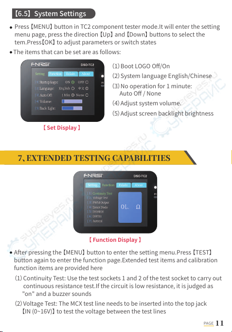
(1)Boot LOGO Off/On
(2)System language English/Chinese
(3)No operation for 1 minute:
Auto Off / None
(4)Adjust system volume.
(5)Adjust screen backlight brightness
【 Set Display 】
The items that can be set are as follows:
【6.5】 System Settings
Press 【MENU】 button in TC2 component tester mode.It will enter the setting
menu page, press the direction 【Up】 and 【Down】 buttons to select the
tem.Press【OK】 to adjust parameters or switch states
PAGE
(1)CH UPGRADE (Digital Oscilloscope)
a. Use the Type-C data cable with D+ and D- to connect the instrument and
the computer in the off state
b. Wait for about 2s after booting.Observe whether there is a U disk named
"CH BOOT" on the computer.If it does not exist, repeat steps A and B
c. Copy the firmware file starting with CH into the U disk.After the upgrade
is complete, you will see an upgrade prompt at the bottom of the screen:
Update complated
The instrument uses a USB analog U disk for firmware upgrade.The
simulated U disk cannot be used to save or transfer other data.For firmware
upgrade and charging only
Firmware comes in a variety of file formats.Different operating steps need to
be selected according to the situation
The computer system required for the upgrade is Windows 10 or above
External circuits must be powered down,Otherwise it will
damage the device
NOTE!
(3)PWM Output: adjustable frequency and duty cycle, output from the top
MCX jack 【PWM】
(4)Zener Diode: Use the test seat K-A-A area for testing.See description in 【6.3】
(5)DS18B20: Follow the on-screen instructions to insert the temperature
sensor into the test seat and measure
(6)DHT11: Follow the on-screen prompts to insert the temperature and
humidity sensor into the test seat to measure
(7)Autocal: Insert the three-pin short-circuit wire into the 1-2-3 jack of the
test socket.Press 【OK】 button to select Start.Press 【OK】 button again to
start calibration.During the calibration process, disconnect the short wire
according to the prompt.When the progress bar reaches 100%,the
calibration of the current mode of the instrument is completed. No further
action required
NOTE:1.The firmware starting with the prefix "CHD" is the firmware of the DSO
oscilloscope part.The firmware starting with the prefix "CHT" is the firmware of
the TC2 transistor part
2.Only one firmware can be upgraded each time. If you need to upgrade
multiple firmwares, you need to repeat steps A, B, and C.

(2) MM UPGRADE (Transistor Detector)
a. Use the Type-C data cable with D+ and D- to connect the meter and the
computer in the off state
b. Press and hold the down arrow key, turn it on, wait for about 2s, and
observe whether there is a U disk named "MM BOOT" on the computer
(at the same time, the lower left corner of the screen displays: MM Boot),
if not, repeat steps A and B
c. Copy the firmware file starting with MM into the U disk to complete the
upgrade
NOTE: After the upgrade is complete, the system will automatically restart.If you
do not need to upgrade, you can short press the power button to reset the
system or long press the power button to shut down
PAGE
A:When the battery is fully charged, the charging indicator will change from red
to green
2: Why does the tested waveform keep shaking left and
right and cannot be fixed?
1: How to judge whether the battery is fully charged?
A:The trigger voltage needs to be adjusted, that is, the yellow arrow on the
right.In trigger mode, press the up and down keys to adjust the trigger voltage.
After adjusting the yellow pointer between the upper and lower part of the
waveform, the waveform can be triggered and fixed
A: The battery voltage signal is a stable DC signal, and there is no curve
waveform.When adjusting the vertical sensitivity in DC coupling mode, there
will be an upward or downward offset line waveform.If it is AC coupled, there
is no waveform no matter how you adjust it
3: Why is there no waveform when measuring a battery
or other DC voltage?

PAGE
A: The mains power grid is generally polluted and contains more high-order
harmonic components.The superposition of these harmonics on the sine
wave will show a distorted sine, which is a normal phenomenon.
Generally,the mains waveform is distorted and has nothing to do with the
oscilloscope itself
4: Why is the measured mains 220V waveform not a
very standard sine wave, with distortion?
A: Please unplug the probe and USB cable.Press 【AUTO】 button to enter the
calibration confirmation interface,Then click the 【OK】 button to enter the
automatic calibration
5: Why is there no signal input,The baseline (OV) on the
screen and the arrow on the left (OV indicated) are not
the same, there is a relatively large offset?
A: Because the turn-on or turn-off voltage of the MOSFET or IGBT is greater
than 5V (the maximum supply voltage of the chip)As a result, the MOSFET
or IGBT cannot be turned on or off normally.Therefore, only its equivalent
parameters can be measured
6: Why do the results obtained by measuring MOSFET
and IGBT are diodes, capacitors and other parameters?
Product name: Oscilloscope Transistor Tester
Brand / Model: FNIRSI / DSO-TC2
Manufacturer: Shenzhen FNIRSI Technology Co., Ltd.
Website: www.fnirsi.cn
Address: Building C, Weihuada Industrial Park, Dalang Street, Longhua District,
Shenzhen, Guangdong, China
PAGE
1. After receiving the device, please use it after it is fully charged
2. When measuring high voltage, it is forbidden to touch any metal part of the
oscilloscope to avoid the risk of electric shock
3. It is forbidden to use it while charging the device
4. Do not place the machine in a place that is unstable or may be subject to
strong vibrations
5. Do not place the machine in places with high humidity, dust, direct sunlight,
outdoors or near heat sources
6. USB firmware upgrade only supports WIN10 and above.Drag in files other
than release firmware is prohibited.May cause irreversible consequences
7. The instrument is powered by a built-in 3.7V rechargeable lithium battery,
which can be used for a long time.Please use the power adapter to extend
battery life
8.When not in use for a long time, the battery should be discharged to 3.7V
before storage
9.When using the oscilloscope mode, pay attention to the selection of the gear.
The gear of the oscilloscope should be consistent with the gear of the probe.
10.When calibrating,The BNC probe needs to be unplugged, or the positive and
negative poles of the probe are short-circuited

www.fnirsi.cn
Table of contents
Other Fnirsi Test Equipment manuals

Fnirsi
Fnirsi DPOX180H User manual

Fnirsi
Fnirsi FNC88 User manual

Fnirsi
Fnirsi FNB38 User manual

Fnirsi
Fnirsi 1013D Instruction sheet

Fnirsi
Fnirsi FNB48P User manual

Fnirsi
Fnirsi SG-003A User manual

Fnirsi
Fnirsi FNB48P User manual

Fnirsi
Fnirsi DPOX180H User manual

Fnirsi
Fnirsi FNB28 User manual

Fnirsi
Fnirsi FNB48 User manual


