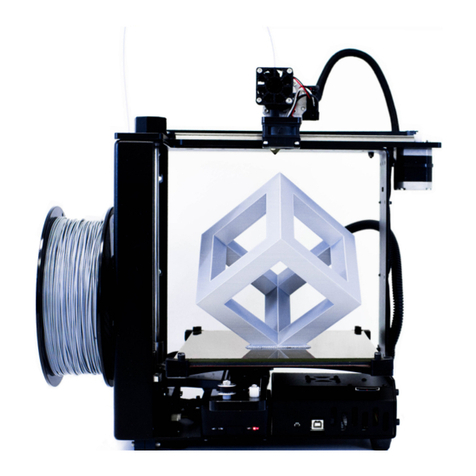
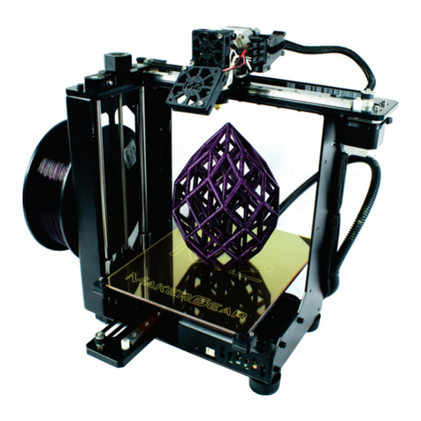
MAKERGEAR M2 User manual


2
Beginner’s Guide to Getting Started with the M2
Congratulations on your purchase! You’ve made an excellent choice for your 3D printing needs!
If you’re new to the world of 3D printing, there is a lot to take in at first, but there are also a lot of
resources to help you if you get stuck. This first page tells you how to get to that help. To make the
resources immediately available, two of the first things you’ll want to do are register your M2,
and join the forum.
To Register Your Printer:
Send an email with your Name, Address and the Serial Number from the printer to:
(The serial number is located above the bar code, on a sticker on the back of the machine.)
To Join the MakerGear Users Forum:
http://forum.makergear.com/
The forum is your best place for getting a quick answer. It has a lot of users who’ve been around the
block a few times. (It’s a safe bet that you’re not the first person to encounter whatever problem you
run into.)
Or, if you have no issues to resolve, feel free to post there and just introduce yourself….it’s a friendly
bunch, and every one of us had to get started the same way.
(Usual forum rules apply –keep it friendly, no bashing, hate-speech, inflammatory rhetoric, actively
promoting other printers, etc. MakerGear has not expressly forbidden it, but you’ll run the risk of
ticking off a lot of people who think the M2 is the “bee’s knees”, and I’ll tell you up front, they’ll
defend it. Final discretion rests with the moderators. If they cause a ruckus, or have the potential to
do so, you can expect your posts to start disappearing, so keep it polite.)
To Contact MakerGear Technical Support:
You can also contact MakerGear directly for support, although your first resource should probably be
the forum, since you’ll likely get a quicker response from the larger group.
MakerGear tech support is via email….and they are generally very quick to respond.
If you need to contact MG support for assistance with your machine, follow the instructions at the
link below:
http://www.makergear.com/pages/support-1

3
Contents
Tools List 04
Quick Start Guide –Single Extruder
1. Setting up the Machine/Installing Driver 05
2. Checking the Level 05
3. Adjusting the Level 06
4. Preparing the Plate 08
5. Establishing Communication with Your Slicer Software 09
6. Checking and Setting the Z-Endstop 10
Checking the Z-Endstop Gap
Cold Setting the Z-Endstop
Hot Setting the Z-Endstop (all nozzle styles)
Hot Setting the Z-Endstop (V4 style nozzle)
7. Preparing to Print 14
8. Printing 15
9. Calibrations 16
Calibrating the Z-Offset
Calibrating the Tension on the Filament Drive Screw
Calibrating the Extrusion Width
Quick Start Guide –Dual Extruder M2
Getting Started with the Dual Extruder System 17
Adjusting the Right Nozzle Gap 18
Starter S3D Profiles for the Dual 19
Tips for Printing PLA 20
Troubleshooting Tips 22

4
Tools List
Although you can get by without them, the tools below just make it easier to use a 3D printer.
1. Metric Feeler Gauges (Amazon) - They are invaluable in setting the Z-stop.
2. Calipers - Needed for calibrating the extrusion widths and heights.
3. Hairspray/Washable Glue Stick/Wide Blue Painter’s Tape -Any of these can be used to stick the
prints to the plate and you might prefer one method over the other.
4. Sprue (Wire) Cutters/Tweezer Nose Pliers - For removing support and cleaning up your prints.
5. Burr Grinders (Amazon) - Are also great for removing junk if you have a Dremel tool.
6. Fine Grade Sand Papers - For smoothing your finished prints.
7. Eye Protection -Always wear safety glasses or goggles when you are cleaning up a print.
(It’s very easy for a snipped bit to fly up and hit you in the eye, even if you wear regular glasses.)
8. Thin Bladed Spatula/ Honed Putty Knife/Single Edge Razor Blade with holder - For prying the
print off the glass. (“Cricut”makes a good one.) (Amazon)
9. Gloves - Useful when prying a print off the glass. (You can cut yourself when the print lets go.)
10. Painter’s Masking Tape -Used to hold the Z-knob in place while leveling and setting the Z-stop.
(There are printable options for Z-knob holders on Thingiverse as well.)
11. Spare Hot End, Nozzle and Plate –Handy to have because when you need them, it’s immediately.
12. Optional Bed Surface - As opposed to the hairspray and spatula route, you might want to try one
of the bed surfacing options below:
PEI surface - Pros: Releases easily when cool, holds beautifully under heat without adhesive,
stays perfectly flat if it is applied correctly, and is easy to use for beginners. Cons: Has to be
applied to the borosilicate glass with sheet tape. (Think screen protectors.)
Zebra plate - Pros: Heavy flexible plate with copper inserts on both sides. Replaces the glass,
no application needed. Holds beautifully without adhesive for certain filaments. Excellent
release for large prints due to the flexible nature. Cons: Can warp over time, or at higher
heat. Not the best choice for beginners due to flex. Cannot be used for tall ABS prints.
MIC6 tooling plate - Pros: Aluminum replacement plate - distributes heat all the way to the
edges of the plate for better adhesion. Cons: Does require adhesive. Plate has to be ordered,
cut to size, and the faces bead-blasted (if desired) - you can’t buy the correct size off the shelf.
There may be extra costs for custom sizing.
(There is more information on what the surfaces do, how to apply them, and what makes them better
for certain prints in the Modifications section of the forum.)

5
The Quick Start Guide
Single Extruder M2
1. Setting up the Machine:
Choose a solid, stable, desk, table, or workbench to set up your machine.
(These things vibrate when they print.)
Because the M2 changes slightly as improvements are incorporated into the base model:
Carefully read through all of the current instructions provided by MakerGear (included in your box)
before assembling.
You can also direct download your RAMBo Windows Driver before assembly, to have it ready. It is
available at the page linked here:
http://makergear.wikidot.com/m2-firmware
Assembly is easy, and generally all that is required is to clip a few ties, plug in a connector or two,
tighten a few screws to attach the spool holder, and load your driver (if you use Windows). Keep in
mind, the User Manual and Wiki might not get updated as often as the instructions that came in your
box. It’s a rapidly evolving field, and MakerGear is continually testing and incorporating the latest
improvements. (If they don’t agree, follow the current instructions you received in the box.)
There is an excellent step-by-step demo for the basic setup process here:
M2 Initial Setup: https://www.youtube.com/watch?v=vCKDJlZKubA
2. Checking the Level:
If you purchased a pre-assembled (non-auto-leveling) machine, it has already been leveled by
experts, and the packaging protects it very well during transport. It is highly unlikely that you will
have to adjust the level, but it’s not a bad idea to check it once you have assembled the machine,
before you have extruded through the nozzle.(If you have extruded, clean any drips off of the nozzle
with the tweezers while it is cooling. You need a clean nozzle surface for this test.)
You need:
Masking Tape
Sheet of copy paper
Pull up a chair in front of the machine. With the power off to the
machine, center the nozzle over the bed. With your hands underneath
the Y-axis rail, (not the spider), slowly lift the bed until it is a couple of
inches under the nozzle.
Sit in front of the machine, get comfortable, and position your eyes level
with the bottom of the nozzle.

6
Turn the Z-axis knob to finish bringing the bed up until it almost touches the nozzle.
(You should still be able to see a small gap at eye level, about the thickness of the sheet of paper.)
When the nozzle is close enough, use the masking tape to tape the Z-knob into place, to keep it from
turning. (It will hold the bed at that position until the tape is removed.)
Without taking your eyes off of the gap between the nozzle and the bed, (using your hand) slowly
move the print head all the way to the left, all the way to the right, and then back to the center along
the X axis.
If the bed is un-level from left to right, you will see the size of that gap change. (Stop if the nozzle hits
the bed, you might need to lower the bed a fraction to run your test. Re-center the nozzle, and re-
tape the Z-knob.)
Perform the same test for the front-to-back direction by again, centering the print head, and then
slowly moving the bed forward and backward along the Y axis (by hand). Keep your eyes on the gap
at eye level while you do it.
Note: After you have eyed the gap, check it by sliding the sheet of copy paper between the nozzle and
bed at various points along the axes to check the resistance. The paper should slide in and out with
the same slight resistance at all points.
If the size of the gap doesn’t change by more than 0.1 mm (roughly the thickness of the sheet of
paper) from the center to either side of the bed, it’s in good shape. If the gap changes by more than
0.2 mm (two sheets of paper) it’s going to need to be adjusted.
To help keep your plate level for a long time:
1. Do not lift the bed using the spider or the bed plate; always lift from underneath the Y-axis rail.
2. Don’t try to manually lift the bed with the stepper motors engaged. (It won’t budge.)
3. Don’t pry stubborn prints off of the plate while it’s still on the bed. Remove the plate first.
Note: Because glass is rarely perfect, you might see some isolated low spots or bulges in the glass as
you move the print head and the bed. If the bulge or low spot is small enough, it shouldn’t affect your
printing –what you are looking for is an overall lean in one direction over another.
3. Adjusting the Level:
It’s very easy to quickly make minor adjustments to the bed level
by turning the three adjustment screws on the triangular plate
(located under the bed) that the spider sits on, if you understand
how turning each of the screws affects the plate.
The diagram on the next page is very handy for explaining it, and
it’s a good idea to print out a copy and keep it near the printer for
reference.

7
Use the Front Adjustment Screw and Rear Adjustment Screw to adjust the size of the gap along the Y
axis. (Front to back.)
For example: Say the front of the bed is too low relative to the rear of the bed, (the gap is larger at
the front of the machine than at the rear), you would position the nozzle at the area of the largest
gap, watch it at eye level, and slightly loosen the Front Adjustment Screw to bring the plate up until
the gap at the front is the same size as the gap at the rear of the plate. Check the gap (all the way
forward and back) again. You never want to make big adjustments to the screws, use tiny increments
and check the results, then adjust more if needed.
To adjust the gap from left to right on the plate, (along the X axis), you use only the Right Adjustment
Screw. That screw causes the plate to rotate relative to an axis that runs between the other two
screws, so if you tighten the gap on the right side of the bed, the gap grows larger on the left side of
the plate.

8
To correctly use this screw, position the nozzle directly over the widest part of the gap, refer to the
diagram for the correct direction to turn the screw, keep your eye on it and either slightly tighten or
loosen the Right Adjustment Screw to reduce that gap by half. Check the gap all the way again,
choose the next highest gap, and adjust once more if needed. Again, only close half of the gap.
For more information:
A more detailed description (with photos) of Setting the Z-Stop and Bed Leveling is available on the
MakerGear Forum: http://forum.makergear.com/viewtopic.php?f=3&t=2783
And a video of the more expert leveling process is available at the link below:
https://www.youtube.com/watch?v=R53wWwktH0s
Note: The diagram shown above is a simplified view of the leveling procedure, designed to take care
of minor adjustments before they become major ones, and it assumes starting with a basically level
bed. If you have a large variance at any of the corners, or have let the bed get severely out of level,
you will need to read the more detailed descriptions and watch the video for a better understanding
of the leveling forces at work. (There are actually 3 axes that the plate rotates through, and major
adjustments would need to be handled according to the video instructions.)
Remove the tape from the Z-knob, and gently lower the bed (supporting it), when you are done.
4. Preparing Your Plate:
If you are planning to use the Polyimide (Kapton) tape on your glass plate, remove it from the bed
clips and apply the tape at this time. (The tape is used to improve print adhesion for certain filaments,
and can be used in conjunction with other adhesives if needed. It can also level out a slightly low spot
in the glass, and it provides protection from possible chipping of the glass when removing prints.)
Same goes for blue Painter’s Tape, if you intend to try it in lieu of adhesive. Evenly apply 3 strips of
tape along the long edge of the plate, (with no overlap), before the next test. If you have purchased a
separate surface (such as PEI material) you will also want to apply it before performing the next
check.
Note: And this is important….Any time you change the height of the print surface relative to the
nozzle, you will need to re-set the Z-Endstop. If you set the Z-stop initially using painter’s tape, and
then change out the tape with fresh painter’s tape, that is not usually enough to warrant re-setting
the Z-stop.
But if you switch from painter’s tape to Kapton tape, that is. Switching to a different plate, or
applying a different surface to your existing plate, is going to change the gap between the nozzle and
the print surface. Keep that in mind if you use multiple plates for different things on your machine.
The use of adhesives alone is not enough to affect the gap.

9
5. Establishing Communication with your Slicer Software:
At this point, if you have not already done so, you will want to establish communication with your
slicer software or machine control software, since you will be using the controls to heat the nozzle
and bed for the next test. (Setting the Z-Endstop.)
Basically, the way the 3D printing process works is that a 3D model (created in any appropriate 3D
modeling program) is “sliced” in another program, which can look at that model and automatically
convert it into a series of thousands of “G-Code” commands that tell the printer when to turn on the
fans and the nozzle, how much to extrude, how far to travel before turning, when to stop printing,
etc. This slicer software can be used to either send instructions to the printer over USB, or by saving
a G-code file with the instructions to an SD card, which is then inserted into the card reader on the
printer. (In an assembled M2, the SD card is shipped inside the card reader on the machine.)
The M2 can be used with the (recommended) Simplify3D slicer software, or the free open source
option of Slic3r through a Printrun (aka: Pronterface) or Repetier interface. MakerGear has nothing
to do with the development of any of these 3rd party programs, so you’ll need to access the
individual web sites for specific usage instructions. (There are users on the MakerGear forum familiar
with both methods.)
Simplify 3D:
Purchase and install: https://www.simplify3d.com/
Setup Guide: https://www.simplify3d.com/support/hardware-setup-guides/makergear/
Tutorials & Guides: https://www.simplify3d.com/support/
http://jinschoi.github.io/simplify3d-docs/
Printrun/Pronterface:
Download and install: http://koti.kapsi.fi/~kliment/printrun/
Setup Instructions: http://makergear.wikidot.com/m2-getting-started
Slic3r:
Download and install: http://slic3r.org/
Tutorials & Guides: http://manual.slic3r.org/
After you have downloaded and installed the software, (following the setup instructions at the above
links), turn on the M2, establish a connection with the software, and practice using the Jog Controls
/Machine Control Panel to heat the nozzle and bed, (215°C/60°C), move the plate up and down (by a
few millimeters), and move the print head left and right (by a few millimeters). At this time, avoid
using the Home Z button on the Jog Controls. (You will be checking/setting that in the next step.)
(It’s also not time yet to load the filament, since if you extrude through the nozzle, you’re going to
have to heat it up, retract the filament, and clean the nozzle off before continuing.)
Once you get comfortable with basic manipulation of the controls, continue to the next step.
10
6. Checking and Setting the Z-(End)Stop: (It’s all about the gap!)
In 3D printing, the most critical setting that you have to get
absolutely right is the size of the gap between the tip of the
nozzle and the print surface when you lay down your first
layer. If that gap is too large, you’ll be squirting plastic into
thin air, your filament won’t stick to the plate, and you might
experience poor bonding. If it’s too small, you’ll be smearing
plastic across the plate, squishing it out the sides, and
potentially jamming the nozzle.
The Z-EndStop is set once before you begin printing, to lock the Z-Home value, so that the gap
between the nozzle and the surface of the plate comes out to just at or below one layer height
(0.20 - 0.25 mm) while the bed and nozzle are at the correct
temperature for whatever filament you are printing.
(Additional fine tuning is required of course, since you will be
printing a lot of different filaments at different
temperatures.) But you want to get as close as you can to
that ideal with the Z-Home.
On a pre-assembled M2, the Z-stop is set once for you, using a Kapton-coated glass plate, and the
cold-set method.
(If the plates now come with the Kapton tape pre-applied, then the test was probably performed with
your plate. You will just need to check the Z-stop gap to make sure the bolt didn’t shift during
shipping, and to make sure the bolt is tightened.)
The gap can be approximated by using a standard business card, while the machine is cold.
For more accuracy you want to set the gap by heating the bed and nozzle to printing temps and using
aMetric Feeler Gauge (0.15 mm to 0.20 mm).
Either way, after you have checked or reset the Z-stop, you will fine-tune the gap using
a control in your slicing software called the Z-Offset, which you will determine later in
the final Calibrations step.

11
Checking the Z-EndStop Gap:
(Do not press down on the bed while checking the gap.)
Quickest method:
Home Z while the M2 is turned on but not heated, center the print head, and slide a business card in
and out of the gap between the nozzle and the bed. It should just fit under the nozzle without
binding, while perfectly flat.
Better method:
Heat the nozzle to 215°C and the bed to 60°C, center the print head, Home Z, and slide a folded sheet
of copy paper in and out. The folded paper should just slide in and out without binding.
Best method:
Heat the nozzle to 215°C and the bed to 60°C, center the print head, Home Z, and use a set of metric
feeler gauges to determine what the gap actually is, by sliding various gauges into the gap and seeing
which one fits perfectly. You want the gap to fall into the 0.15 mm to 0.20 mm range.
Once you’ve checked the gap, use one of the methods below to adjust it, if needed.
Cold Setting the Z-Endstop: (All Nozzle Styles)
MakerGear has a video demonstrating the cold-set calibration process:
MakerGear M2 Z-Endstop Calibration: https://www.youtube.com/watch?v=j0Cz6jPPECM
Hot Setting the Z-Endstop: (All Nozzle Styles)
This first method works for all nozzle styles.
(It is a lot easier to set the gap for the V4 style nozzle (shipping standard on machines as of 1/1/16) so
if you have that nozzle, and a set of metric feeler gauges, you can skip to the next section.)
You will need:
A 0.15 - 0.20 mm Metric Feeler Gauge; or one sheet of copy paper, folded (approx. 0.20 mm when doubled)
Masking Tape - to keep the Z-knob from turning
A narrow 7-mm wrench or a pair of needle nose pliers
1. Position the nozzle in the center of the bed.
2. Make sure the heated bed plate is seated flat between the rubber corners.
Clip the prepared glass plate to the bed.
(If you have extruded through the nozzle, heat the nozzle, retract the filament completely, and
clean off the nozzle tip with tweezers. You need a clean flat tip on the nozzle before proceeding.)
3. Set the bed temperature to 60°C and the extruder temperature to 215°C, using the Jog Controls or
Machine Control Panel.

12
4. Remove the spool of filament from the holder - it will be in the way.
5. Loosen the nut on the Z-stop bolt (counterclockwise) with a
7 mm wrench, or a pair of needle nose pliers.
(It’s very hard to reach with your fingers.)
6. Lift the bed (from under the Y axis rail) until the bed is a
couple of mm away from the tip of the nozzle.
7. Use the Z-knob to bring the bed up to a distance of
0.15 –0.20 mm from the nozzle, using the metric feeler
gauge* to set the distance. The gauge should slide in and
out with a slight resistance, but not stick.
(Do not touch the nozzle.)
*Alternatively, you can use a folded sheet of copy paper, which measures approximately 0.20 mm.
8. Tape the Z-Knob into place to keep the bed from moving.
9. Locate the loosened Z-stop bolt under the bed.
Turn the bolt from under the bed until it contacts and just triggers the LED light switch above the
plate, with the bed in the current taped position.
10. Remove the tape and gently lower the bed about halfway down. Tape it into place again.
While holding the bolt stable so that it doesn’t turn, tighten the nut to fix the bolt into position.
11. Remove the tape and Home Z to check the gap.
(Make sure the gauge still slides in and out without compressing the springs in the spider.)

13
Hot Setting the Z-EndStop: (V4 Style Nozzle)
1. Position the nozzle in the center of the bed.
Make sure the heated bed plate is seated flat between the rubber corners.
Clip the prepared glass plate to the bed.
2. Set the bed temperature to 60°C and the extruder temperature to
215°C, using the Jog Controls or Machine Control Panel.
(Retract any filament and clean any drips off of the nozzle with the
tweezers –you need a clean, flat surface on the nozzle.)
3. Swing the fan up out of the way so that you can reach the screw
that secures the hot end in the clamp.
Raise the bed to about a half inch underneath the nozzle.
Tape the Z-knob to keep the bed from moving.
4. Slightly loosen the screw that holds the V4 hot end in the clamp,
using the provided M3 allen driver. (Not enough to drop the hot
end out; you just want to be able to shift it in the clamp.)
5. Use the driver to press the hot end up slightly in the holder, and
tighten the screw just enough to keep it from falling out of the clamp.
(Do not let the hot end rotate in the mount, and be careful- it’s hot.)
6. Remove the tape from the Z-knob.
Home Z using the Jog Controls.
Place the (0.15 mm to 0.20 mm) feeler gauge underneath the raised nozzle.
7. Loosen the screw holding the hot-end again, and tap the top of the heater block with the M3 driver
to cause it to drop down onto the feeler gauge.
Tighten the screw to secure the hot end.
Swing the fan back down into position.
8. Lower the bed and Home Z again to check the gap with the feeler gauge.

14
7. Preparing to Print:
You will do this each time you prepare to print a model.
1. Cut a flat end on the end of the filament from the spool and load the filament onto the spool
holder with the spool unwinding towards the back of the machine. Take the cut end up through
the filament guide, through the guide tube, and into the 2 mm hole on top of the filament drive.
(Do not let go of the end of the filament until you have fed it through the filament guide.)
Video on the process here:
MakerGear M2 Filament Feeding: https://www.youtube.com/watch?v=Ni7xN4616No
2. Attach your filament dust wiper*. The filament dust wiper prevents clogs from bits of dust that
wind up on the spools during manufacturing, and it’s a good idea to always use one.
*(A small clip with a folded tissue inside, loosely wrapped around the filament before it goes into the
filament guide. A wide variety of printable alternatives are also available on Thingiverse.)
3. Prepare your plate with whichever adhesive you choose to use. (Hairspray, gluestick, none.)
If you choose to use hairspray or gluestick, you need to apply a medium heavy, even base coat
while the plate is cold, and let it dry completely before printing on it. It’s not necessary to wash
the base coat off each time you use it, you can just refresh the base coat with a spritz before new
prints, and replace the base coat when it gets uneven. If you choose to use no adhesive, the plate
has to be perfectly clean, (as in…wash it with soap between uses, and don’t touch it with oily
fingers), and your first layer gap has to be spot-on. Clip the dried plate to the bed.
4. Heat the nozzle to the temp necessary for your filament on the Jog Controls or Machine Control
Panel.
(You must heat the nozzle up to temperature before you can extrude.)
There is a block in the firmware that stops extrusion if the nozzle temperature is below 180°C.)
5. Extrude 100 mm or so to clear the nozzle and prime it.
Preferably in 20 mm batches, not all at once.
(While you can get away with extruding 200 mm of PLA through in one batch, if you try it with
some of the softer filaments, you’re eventually going to jam your nozzle, so get into the habit of
extruding in small batches to prime and clear your nozzle.)

15
6. Adjust any appropriate settings in Simplify3D or Slic3r for whichever filament you are printing.
There are generic starting settings for PLA and ABS pre-loaded into S3D. Tested successful settings
for various other filaments are discussed in the Filaments section of the forum and many are also
listed here:
Insta’s Filaments that Work: http://www.forum.makergear.com/viewtopi ... =11&t=1951
These settings are a good place to start. Remember that you are likely going to have to adjust them
a bit, since one kind of PLA does not print exactly the same as another kind from a different
manufacturer. But for things like retraction rates and amounts, bridging settings, and fan speed
settings, they give an excellent jumping off point. (Fine tuning as you go along will result in
excellent prints.)
Note: Since PLA is the easiest filament to print, (and a good one to start with), a brief discussion of
its characteristics is provided in a separate section before the Troubleshooting Tips.
8. Printing:
1. Import your model.
2. Slice it using your chosen slicer software.
3. Pre-heat the bed using the Jog Controls. (Saves time).
4. Send the model to be printed. The software will heat the nozzle, move it into position, and start
extruding.
Note: The M2 uses a pre-configured starting script in Simplify3D that moves the print head forward,
back, then off to the right of the bed, extrudes 20 mm or so of filament to prime the nozzle, and then
wipes itself off on the plate before starting the print. This is normal. The extruded thread can be
captured with the tweezers as it falls and removed, or left to fall beside the plate and picked off later.
If you pre-heat the nozzle as well, you might have to deal with oozing filament from the nozzle over
the plate. Use the tweezers, not your fingers, to capture the drips before the print starts.
(It’s hot, and you’ll leave oils on the plate.)
Make sure that you take the time to run the few calibrations on the next page as your first prints.
It makes for fewer errors in your prints down the road.

16
9. Calibrations:
There are a few very important calibrations that you will want to perform before you hit the ground
printing.
1. Calibrate Your Z-Offset:
This simple but critical calibration will save you a lot of headaches. The file you will want to use and
instructions are found at the link below. Do this once for each type of filament. (PLA, ABS, PETG etc.)
Calibrate the Z-Offset: http://forum.makergear.com/viewtopic.php?f=3&t=3124
2. Calibrate the Tension on your Filament Drive Screw:
Do this once for each type of filament. (PLA, ABS, PETG, Flex, etc.)
Having the incorrect tension on the filament drive screw also causes a lot of printing problems.
Heat the nozzle, feed the filament in and retract it completely using the Jog controls in Simplify3D,
then examine the end, and refer to the guide here:
Setting the Filament Drive Screw Tension:
http://www.forum.makergear.com/viewtopic.php?f=3&t=2694
3. Check the Calibration of Your Extrusion Width:
The default dimensions of 1.75 mm filament diameter and multiplier of 0.9 give a surprisingly
accurate result as far as filament extruded width goes, but if you want to fine tune it (for instance, if
X-Y plane dimensional accuracy is critical in your design), the process for doing that is below. Check
the width of the extruded wall with an average 1.75 mm filament diameter, and adjust the 0.9
multiplier according to the instructions.
Calibrate the Extrusion Width: http://forum.makergear.com/viewtopic.php?f=3&t=1964
That’s it….go make something!

17
Quick Start Guide
Dual Extruder M2
Getting started with the dual extruder system:
Setting up the machine for the dual is very similar to the instructions for the single extruder, and for
the most part, you can follow the getting started guide for the single extruder with a couple of
exceptions, which I will go over below.
But first……..If this dual extruder is your first 3D printer, I’m going to offer some free advice:
*************Learn to use one extruder before you try to print with two ********************
When you print with two hot nozzles simultaneously, you are going to have a lot of issues with oozing
filament from the inactive nozzle, and will need to print a shield around your object to catch the
drips. The slicer software can handle this for you, but you will still see all of the potential problems
with your prints that are normal with this kind of manufacturing process, and if you can’t see what’s
going on, you can’t stop the print before you waste a lot of time and filament.
The Differences:
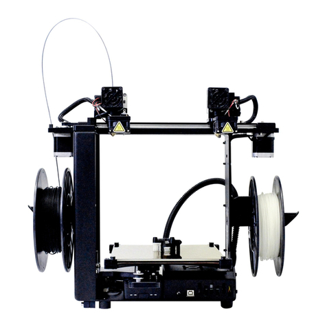
1. Obviously, you have two extruders, not one. According to the conventions for the M2:
The left hot end is Tool 0.
The right hot end is Tool 1.
You will use those labels when you set the temperatures and conditions for each extruder in your
slicer software. And the difference when using two extruders in a dual is that you have to specify
which tool you want to work with when you adjust the settings, or use the Jog Controls.
2. When you check the Level and set the Z-(End)Stop for the machine, you will set these using the
left nozzle (Tool 0). (While you are setting these, you can raise the right nozzle slightly in the
clamp, so that it does not contact the feeler gauge before the left nozzle does.)
Only the left nozzle (Tool 0) can span the entire bed. The right nozzle (Tool 1) cannot reach all the
way to the edge of the plate on the left. (It’s something to keep in mind when you are deciding which
filament you want to extrude out of each nozzle later.)
3. The Dual M2 comes with the V4 style nozzles. (When you set the Z-stop, you can use the second
listed Hot-Set method, which does not require fiddling with the Z-stop bolt and nut.
4. After you have checked the level and set the Z-Stop using the Left Nozzle (Tool 0), there is an
additional step that you have to take with a dual before you can set the Z-Offset in the
Calibrations step. If you have a Dual setup, you will be forced to set one gap that has to work
perfectly for both nozzles. Since those might be extruding at different temperatures, (different
heat expansion), you will have to adjust how you set the gap by changing how far down you seat
each nozzle in the clamps.

18
Adjusting the Right Nozzle Gap
Set the height for the right side nozzle depending on how you plan to use it.
Different Colors of the Same Filament
If you plan to use the machine to print filaments that print within the same temperature range, (ex:
dual color printing with PLA), do the following:
1. Clean any drips off of the nozzles if you have extruded through them. (Your tweezers are good for
this while the nozzle is cooling off.) You’ll need a clean flat nozzle surface for this.
2. With the extruders and bed cold, slowly raise the plate up past the Z-EndStop, until it actually
touches the left nozzle. (Nozzle 0.)
Tape the Z-Knob into place so that it does not allow the bed to move.
3. Loosen the screw that holds the right Hot End (1) in place, and press it down with the
M3 hex driver until the right nozzle also contacts the plate.
Do not let the Hot End rotate in the clamp.
4. (Check the gap from eye level. There should be none.)
Tighten the screw.
Different Filaments in each Extruder
If you want to use the left extruder to print one kind of filament, and the right extruder to print a
different kind of filament with a widely different temperature range, (ex: left extruder PLA, right
extruder PETG), you need to set the height of the right nozzle while everything is heated up to the
correct temperatures, in order to maintain the relative height of the gap between the plate and each
nozzle. (Not doing so will have you constantly adjusting Z-Offsets, or worse, will cause gaps, failed
bonding, and poor print quality when both are used at the same time.)
1. Remove the plate from the bed if you have any kind of applied surface on it, and turn it over so
that the bare glass is facing up. (You do not want to hit plastic or tape with a hot nozzle.)
Clip it in place.
2. Heat the bed up to 60°C. (You don’t need to take it all the way up to PETG or ABS temps.)
3. Loosen the screw that holds the right Hot End (1) in place, and raise it slightly in the seat before
lightly tightening. (Do not let the Hot End rotate in the holder.)
4. Heat the extruders to the correct temperatures for what you will be printing out of each nozzle.
5. Retract any loaded filaments completely and clean off the tips of the nozzles.

19
(When you choose which filament goes where, remember that the right extruder (Hot End 1) cannot
reach all the way to the left side of the plate, and for dual prints, you are limited to approx. 170 mm
along the X-axis.)
6. When everything is at temperature, carefully raise the plate up past the Z-End Stop, until the bare
glass actually touches the left nozzle (Nozzle 0).
Tape the Z-Knob into place so that it does not allow the bed to move.
7. Carefully loosen the screw that holds the right Hot End (1) in place, and press it down with the M3
hex driver until the right nozzle also contacts the glass.
(Check the gap from eye level. There should be none.)
Tighten the screw.
(If you let the plate and nozzles cool in place you will see a
larger gap under the hotter nozzle, which is what you want.)
By doing this, you have adjusted the relative gap on each nozzle to account for the expansion it will
undergo at its respective filament printing temperature.
Now you can set one Z-Offset that will apply equally to both nozzles.
Starter S3D Profiles for the Dual
Because setting up the profiles for a dual extruder in Simplify3D is significantly more complicated
than setting up for a single extruder, you might want to get started using the shared dual profiles at
the link below.
(Read the discussion there first, please –you will need to make some adjustments to make the profiles
work for you. It’s still going to save you a lot of time setting up.)
Simplify3D Dual FFF Profiles for the M2: http://forum.makergear.com/viewtopic.php?f=13&t=2984
Additional handy resources for using the Dual M2 with Simplify3D are linked below:
Dual Extrusion Wizard|Simplify3D:
https://www.youtube.com/watch?v=qPufaJhyqME&list=PLogLRK5xzNdieu445p2O7wODJpQBVf-Ss
And more discussions and modifications are available on the forum in the M2 Dual Extruder section.

20
Tips for Printing PLA
In order to get the best results with a filament, it helps to know a little something about the
characteristics of that filament when printing. I’m going to list some tips for printing with PLA, but
they are not going to work the same with other filaments. Each has its own likes and dislikes when
printing –you’ll need to do some research on the others as you switch to different filaments.
PLA is fairly stiff, and it warps up as it cools. (Stick it down well. Use adhesive on your plate.)
PLA does not ooze much, you can get by with a Retraction setting of 1.0 mm.
You generally don’t need to Wipe or Coast.
Set your Extrusion Width to be wider than your nozzle hole size, but less than the O.D. of the flat face
on that nozzle, to give the machine correct control over placement.
(Example: For a 0.35 mm nozzle, the correct range is from 0.035 mm to 0.50 mm –so use 0.40 mm)
Set your Layer Height according to the following formula :
Extrusion Width/Layer Height is greater than or equal to 1.8
In our example, with a layer height of 0.20 mm the formula reads 0.40/0.20 = 2.0 which is greater
than 1.8.
You could also use 0.50/0.25 = 2.0, or 0.36/0.20 = 1.8. The reason for this is to give a slightly
squashed layer to give better adhesion, and layer bonding. Any ratio that comes out below 1.8 is
going to start causing adhesion and bonding problems.
(And if math isn't your thing - just set your layer height to be half of your extrusion width.)
PLA is terrible on Overhangs; it sags and droops, or warps up without support.
Cooling it off quickly reduces that effect.
(You will frequently see curled droopy overhangs on the sides of a print that face away from the bed
fan.)
Either print with Support underneath it, hit it with a LOT of cooling, or preferably both. I actually
added a small desk fan to print rear overhangs with PLA, but there is another trick that you can do
that works even better. If you remove the fan guard on the bed fan, it increases the cooling power
exponentially. Just be very careful to not let the filament get drawn into the fan when you are
loading it –the curl in filament tends to point it right at the fan. Also remember to make an
adjustment to your printing temp and bed temp if you remove the fan guard –it cools things off by
about 10 degrees. If you are printing something with an overhang, choose an Outline Direction of
Inside-Out, otherwise use Outside-In.
You can also orient your print on the bed so that the worst overhang areas point directly towards the
fan.
You can reduce your First Layer Speed to around 60% or so to help with bed adhesion if you need to,
and give the filament time to stick to the warm bed.
Other manuals for M2
3
Table of contents
Other MAKERGEAR 3D Printer manuals

MAKERGEAR
MAKERGEAR M2 User manual

MAKERGEAR
MAKERGEAR M2 User manual

MAKERGEAR
MAKERGEAR M3-SE User manual

MAKERGEAR
MAKERGEAR M3 User manual

MAKERGEAR
MAKERGEAR M3-ID Installation and operation manual

MAKERGEAR
MAKERGEAR M2 User manual

MAKERGEAR
MAKERGEAR M3-ID User manual

MAKERGEAR
MAKERGEAR V4 Quick start guide

MAKERGEAR
MAKERGEAR Ultra One User manual